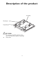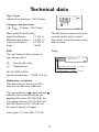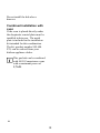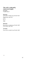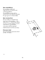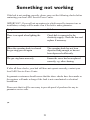
1
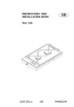
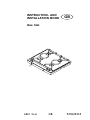
INSTRUCTION- AND
INSTALLATION BOOK
GB
Gas hob
6561 G-m
1
GB
949600555
Your New Appliance
Thank you for purchasing an AEG appliance.
To enable you to use your new hob efficiently and safely, please read this
instruction book carefully before installing or using the appliance, and retain
for future reference. Should the hob be transferred to a new owner please
ensure this instruction book is left with the appliance in order that the new
owner can get to know the functions of the appliance and the relevant
warnings.
If you require further assistance or advice, please contact our Customer Care
Department either by letter or telephone:
Customer Care Department
AEG Domestic Appliances
55-77 High Street
Slough
SL1 1DZ
Tel:
08705 350350
2
Table of contents
Contents
Page no
For the user
Your new appliance ...................................................................................... 2
Safety information ........................................................................................ 4
Description of the product ......................................................................... 5
Operation instructions ................................................................................ 6
Inner- and outer burner ring ................................................................. 7
Burner cover ......................................................................................... 7
Ignition electrode (A) ........................................................................... 7
Thermo couple (B) ............................................................................... 7
Ignition .................................................................................................. 8
Maintenance and cleaning .......................................................................... 9
Splashguard .......................................................................................... 9
Stainless steel surfaces ....................................................................... 10
The ceramic glass plate ...................................................................... 10
The gas burner .................................................................................... 11
Something not working ............................................................................. 21
Service and spare parts ............................................................................ 22
Guarantee conditions ................................................................................ 23
For the installer
Technical data ............................................................................................. 12
Important safety requirements ................................................................ 13
Gas connection ........................................................................................... 14
Mounting .................................................................................................. 15
How to read the operating instructions:
1... 2...Step by step
Hint and tips
Safety information
Environmental information
3
Safety information
Never use plastic or aluminium dishes
on the hob.
These warnings are provided in the
interests of your safety. Ensure you
fully understand them before installing
or using the appliance. Your safety is of
paramount importance. If you are
unsure about the meaning of these
warnings contact the Customer Care
Department for assistance.
Never leave the hob unattended while
deep fat frying, or heating fats and oils.
Child Safety
Young children must not be allowed to
tamper with the hob or play with the
controls.
Installing
Do not install the hob if the ceramic
glass is damaged or cracked.
The hob gets hot when it is in use.
Children should be kept away until the
hob has cooled.
This hob must be installed according to
the instructions supplied. Any
installation work must be undertaken
by a qualified competent person.
Maintenance and Cleaning
Only clean this hob in accordance
with the instructions given in this
book.
Do not alter the specifications or
attempt to modify the appliance in any
way.
Service
Repairs carried out by inexperienced
persons may cause injury or serious
malfunction of the appliance. Repairs
must only be carried out by a
qualified/competent person. Contact
your local AEG Service Centre.
During Use
The hob is intended for domestic
cooking only. It is not designed for
commercial/industrial purposes.
Ensure that all the control knobs are in
the OFF position when not in use.
Disposal
Make the hob unusable by cutting off
the cable.
Do not use the hob if it is damaged in
any way, contact your local AEG
Service Centre.
Dispose of any packaging material and
old appliances at an authorised
disposal site.
4
Description of the product
Air intake
Gas burner
Control knob
Air intake
The primary air intake aperture must
never be blocked by objests of any kind
at any time.
5
Operation intructions
Burner markings
Symbols at each operating knob
indicate which burner is adjusted with
the control knobs.
Left front burner
Left back burner
Right back burner
Right front burner
Panel markings
Each operating knob has a ring
showing the scale of markings.
Off.
Maximum flame
Minimum flame
6
Burner cover/inner burner
ring/outer burner ring
Together with the inner burner ring the
outer burner ring forms a space where the
final mixture of gas and air takes place in
order for the gas burn correctly.
Cover
Burner ring
Please note: It is very important that the
inner burner ring/outer burner ring is
placed correctly, together with the cover.
See installation of the wok burner.
If the burner cover/rings are incorrectly
fitted the burner will not operate
correctly, and the burner may be damaged
within a short space of time. It is also
important, that the inner air ring is placed
correctly.
Ignition electrode (A)
The burner has been provided with an
ignition electrode. As long as the
operating knob is depressed, the
automatic ignition will ensure that a spark
is emitted between the ignition electrode
and the burner cover.
Ignition electrode (A)
Thermo couple (B)
Inner
burner
Thermo couple (B)
The gas unit features fully-secured gas
taps (thermo-couple)
In case the flame goes out, the thermo
couple automatically prevents gas
admission after a few seconds (Max. 90
seconds).
Note: Gas will flow while the operation
button is pressed - See start-up procedure.
7
Outer
burner
Ignition
1. Depress and turn the control knob
for the burner to the left to max.
flame . (Ignition position)
2. The ignition electrode will emit
sparks, and when the mixture of gas
and air is correct, the burner will be
ignited. If it is not possible to
connect the unit to mains, a
match may be used to ignite the
burner.
3. After starting the burner, press the
control knob for approx. 10
seconds to activate the automatic
thermo-couple (thermo sensor
ready).
5. The burner can now be regulated
between maximum and minimum
8
Maintenance and cleaning
For reasons of hygiene and
safety, the cooking zones
must be kept clean. Grease
stains and spilled food
generate smoke when heated,
and can even cause fire.
Splashguard
The splashguard can be removed to
make it easier to clean the surface.
What to do:
1. Hold the splashguard as shown
in the diagram.
2. Lift the splashguard straight up
3. Clean the top surface as
described in “cleaning the steel
surface”.
Be aware of the two retaining
pegs, which are sharp.
4. Replace the splashguard in
position ENSURE that it is
fitted the correct way round.
Never use hard or sharp
implements to lift off the
splashguard.
Do not wash the splashguard
in a dishwasher.
The hob must not be used
with the splashguard off.
9
3. Wipe the ceramic hob clean with
a damp cloth or kitchen towel.
Tough stains can be removed by
rubbing the stain hard with
kitchen towel.
4. Wipe off remaining cleaning
agent with a damp cloth.
5. Wipe with a dry cloth, if
required.
Stainless steel surfaces
Perform daily cleaning with a slightly
damp cloth. For more severe soiling,
use a liquid cream. Always clean the
steel in the direction of the steel finish.
To ensure that the steel retains its
shine, it is recommended that you use
a polishing agent for stainless steel on
a regular basis. Always polish in the
direction of the steel finish (crosswise).
Never use steel wool, metal sponges or
other abrasive cleaning agents.
Make sure that the ceramic glass is dry
when you heat it up again. Ceramic
glass can develop rainbow-like stripes
if heated while damp.
The ceramic glass
Spillages must be removed
immediately, while the burner is still
warm, using a ceramic glass scraper.
Especially damaging are melted
plastic, aluminium, or any foodstuff
containing sugar, including natural
sugar, as these can create permanent
“pockmarks” and craters on the
ceramic surface. After cleaning, polish
thoroughly with the cleaning agent
supplied with the unit.
Immediately scrape off stains caused
by food which has boiled over, spilled
sugar, dishes containing sugar (jam,
juice, etc.), melted plastic and
aluminium foil while the ceramic glass
is still hot. If the ceramic glass is
allowed to cool it may become
damaged.
After use the ceramic glass should be
wiped with a damp cloth with washing
up liquid. For severe soiling you can
follow these steps:
Defects in the ceramic surface which
can be related to the above are not
covered by the warranty.
1. Remove stains etc., with the
ceramic glass scraper.
2. Make sure that the hob has cooled
down. Use a ceramic
cleaning agent such as vitroclen.
Shake the bottle and apply a couple
of squirts to the ceramic hob.
Warning:
Aluminium foil and plastic utensils
should not to be placed on hot
surfaces.
The surface should not be used for
storage.
10
The gas burner
The operating panel with knob, pan
support and burner covers/rings are to
be cleaned with ordinary cleaning
agents.
Do not use any kind of scouring
powder.
Avoid saucepans boiling over. If water
gets into the burner, this should be
removed before re-igniting the burner,
e.g. with a no-fluff cloth.
11
Technical data
Type of gas
Adjusted to natural gas: G20-20 mbar
240 V
1N + PE
Category and pressures
UK: II
20 mbar - 28/37 mbar
2H3+
N
L1
Max. nominal load Q na HS:
Small sized burner=
1,1 kW x 1
Medium sized burner = 1,9 kW x 2
Large sized burner =
2,7 kW x 1
Total=
7,6 kW
The hob must be connected via an
external switch with a contact
gap of min. 3 mm (the main switch
may be used)
FSD
The unit features fully-secured gas
taps (thermo-fuse).
Wiring
HO5V2V2-F
HS = Top calorific value
Q = Nominal load
Blue and brown: 51 mm +/- 3 mm
Yellow/Green: 61 mm +/- 3 mm
ID. CE-048AU-0003
Ignition transformer= 50 HZ - 0,6 VA
Radio-noise reduction
This unit observes the current EECdirective on radio noise reduction.
This gas appliance is -approved and
marked in accordance with the gas
appliance Directive (90/396/CEE), the
low voltage directive (73/23/CEE) and
the EMC directive (89/336/CEE incl.
the agreed directive changes.
Cable type: 0,75 mm² HO5 V2V2-F
12
Important safety requirements
This hob must be installed by
qualified personnel to the
relevant British Standards.
This hob must be installed in
accordance with the Gas Safety
(Installation and Use) Regulations
(Current Edition) and the IEE
Wiring Regulations (Current
Edition).
Any gas installation must be
carried out by a CORGI
registered installer.
Detailed recommendations are
contained in the following British
Standards Codes Of Practice: B.S.
6172/ B.S. 5440, Par. 2 and B.S.
6891 Current Editions.
The maufacturer will not
accept liability, should the
above instructions or any of
the other safety instructions
incorporated in this book be
ignored
The hob should not be installed in a
bed sitting room with a volume of
less than 20 m³. If it is installed in a
room of volume less than 5 m³ an
air vent of effective area of 110 cm²
is required. If it is installed in a
room of volume between 5 m³ and
10 m³ an air vent of effective area of
50 cm² is required, while if the
volume exceeds 11 m³ no air vent is
required.
However, if the room has a door
which opens directly to the outside
no air vent is required even if the
volume is between 5 m³ and 11 m³.
If there are other fuel burning
appliances in the same room, B.S.
5440 Part 2 Current Edition, should
be consulted to determine the
requisiste air vent requirements.
13
Gas connection
Connection to the gas supply
should be with either rigid or semirigid pipe, i.e. steel or copper.
The connection should be suitable
for connection to RC ½ (½ BSP
male conical thread).
When the final connection has been
made, it is essential that a thorough
leak test is carried out on the hob
and installaion.
Ensure that the main connection
pipe does not exert any strain on
the hob.
It is important to install the
elbow correctly, with the
shoulder on the end of the
thread, fitted to the hob
connection pipe.
Failure to ensure to correct
assembly will cause leakage
of gas.
Pressure test
The unit should be pressure-tested
at Max. 150 mbar.
14
Mounting
Caution: In order to avoid a hazard this
appliance must be installed according to
these instructions for installation
The hob unit can be mounted in any
type of kitchen with a table surface
whose thickness is between 28 mm and
40 mm.
Headroom
The distance to any shelves or tops of a
cabinet under the hob is to be at least 47
mm.
Fixing
Screw the fixing brackets out to such an
extent that they can be turned in under
the table top. Tighten the brackets on to Minimum distance
the table top with an ordinary
to side wall:
screwdriver.
150 mm
Cut-out measurements
One rectangular hole is sawn out for the
hob combination chosen.
The depth of the cut-out for any unit is:
490 mm
Reinforcement
Length of hole = sum of all units`
externally measured length, less 20 mm. beams
Mounting of Reinforcement
Beams
A reinforcement Beam, with supporting
flanges at each end, is included with
each two-burner unit. For unit
combinations, a reinforcement beam
must be used between each unit.
15
Minimum distance
to rear wall (nonflammable material):
50 mm
It is not necessary to attach the
reinforcement beam to the table
surface, as it is held in place by a
specially designed moulding, which is
incorporated in the hob units flanges.
Installation in work tops with a
base unit underneath
If the hob is to be installed on top of a
base unit, a board must be mounted
underneath the hob (e.g. 16 mm chip
board).
Min. 140 mm
Min. 16 mm
Aluminium-tape
Seal all joints with aluminium tape.
The board can be mounted as shown in
the diagram.
This installation method prevents the
flames from being extinguished if you
close the door of the base unit hard.
Min. 140 mm
Min. 16 mm
If the back panel of the cupboard unit
is of thin 4 mm material, it will need to
be reinforced.
Aluminium-tape
This procedure will prevent the gas
being blown out if the cupboard door
is slammed shut.
16
Do not install the hob above drawers.
17
Do not install the hob above
drawers.
Combined installation with
oven
If the oven is placed directly under
the dropinette a metal plate must be
installed in between. The metal
plate is included in the installation
kit intended for this combination.
The kit, product number 949 600
970, can be ordered from your
kitchen appliance dealer.
This gas hob can be combined
with AEG Competence ovens
with a maximum power of
3,7 kW.
18
The unit´s externally
measured length
145 mm:
Cooker hood
290 mm:
Two-zone ceramic-top electric hob
Two-burner gas hob
Grill
Fryer
Wok
580 mm:
Four-zone ceramic-top electric hob
Four-burner gas hob
725 mm:
Four-zone ceramic-top electric hob
Installation of a single unit
When mounting a single unit, be it a
half-or full size unit, in a table surface
which is thicker than 30 mm, it is
necessary to make a special notch in
both sides of the cut-out hole, as
shown in the adjacent drawing.
The purpose of these notches is to
create space for the electrical cables.
19
Gas installation
In accordance with local
requirements for domestic gas
cooking appliances.
Gas installation must only be
carried out by an authorised person.
For gas types see technical data.
Gas connection
The gas intake is situated at the
lower rear of the appliance. The
intake has a ½" conical pipe thread
(see fig 1) If the appliance is to be
connected to a gas cylinder,
conversion with the optional
modification kit will be necessary.
Pressure test
The unit should be pressure-tested
at Max. 150 mbar.
20
Something not working
If the hob is not working correctly, please carry out the following checks before
contacting your local AEG Service Force Centre.
IMPORTANT: If you call out an engineer to a fault caused by incorrect use or
installation, a charge will be made even if the hob is under guarantee.
Sympton:
Solution
There is no spark when lighting the
gas
Check hob is connected to the
electricity supply. Check the fuse and
replace if necessery.
When the operating knob is released
the gas ring goes out again
The operating knob has not been
depressed long enough, or has not
been depressed sufficiently.
The gas ring burns unevenly
Ensure the cover has been replaced
correctly, e.g. after cleaning.
If after all these checks, your hob still does not operate correctly, contact your
local AEG Service Force Centre.
In-guarantee customers should ensure that the above checks have been made as
the engineer will make a charge if the fault is not a mechanical or electrical
breakdown.
Please note that it will be necessary to provide proof of purchase for any inguarantee service calls.
21
Service & spare parts
In the event of your appliance requiring service, or if you wish to purchase spare
parts, contact your local AEG Service Force Centre by telephoning:
08705 929 929
Your call will automatically be routed to the Service Centre covering your post
code area.
In-guarantee customers should ensure that the recommended checks under the
heading "Something Not Working" have been made as the engineer will make a
charge if the fault is not a mechanical or electrical breakdown.
Please note that proof of purchase is required for in-guarantee service calls.
Help us to help you
Please determine your type of enquiry before writing or telephoning. When you
contact us we need to know:
1.
2.
3.
4.
Your name, address, post code and telephone number
Clear and concise details of the fault.
Date of purchase
The model and serial number
This information can be found on the rating plate.
Customer Care
For general enquiries concerning your AEG appliance, or for further information
on AEG products, you are invited to contact our Customer Care Department by
letter or telephone:
Customer Care Department
AEG Domestic Appliances
55-77 High Street
Slough, Berkshire
SL1 1DZ
Tel 08705 350350
22
Guarantee conditions
6. The purchaser's statutory rights are
not affected by this guarantee.
AEG offer the following guarantee to
the first purchaser of this appliance:
1. The guarantee is valid for 12
months commencing when the
appliance is handed over to the first
retail purchaser, which must be
verified by purchase invoice or
similar documentation.
2. The guarantee covers all parts or
components which fail due to faulty
workmanship or faulty material.
The guarantee does not cover
appliances where defects or poor
performance are due to misuse,
accidental damage, neglect, faulty
installation, unauthorised
modification or attempted repair,
commercial use or failure to
observe requirements and
recommendations set out in the
instruction book.
3. Should guarantee repairs be
necessary the purchaser must
inform the nearest AEG Service
Force Centre. AEG reserves the
right to stipulate the place of repair
(i.e., the customer's home, place of
installation or AEG workshop).
4. The guarantee or free replacement
includes both labour and materials.
5. Repairs carried out under guarantee
do not extend the guarantee period
for the appliance. Parts removed
during guarantee repairs become
the property of AEG.
European guarantee
If you should move to another country
within Europe then your guarantee
moves with you to your new home
subject to the following qualifications:
The guarantee starts from the date you
first purchased your product.
The guarantee is for the same period
and to the same extent for labour and
parts as exists in the new country of
use for this brand or range of products.
This guarantee relates to you and
cannot be transferred to another user.
The product is installed and used in
accordance with our instructions and is
only used domestically, i.e. a normal
household.
The product is installed taking into
account regulations in your new
country.
23
Before you move please contact your
nearest Customer Care centre, listed
below, to give them details of your new
home. They will then ensure that the
local service organisation is aware of
your move and able to look after you
and your appliances.
France
Senlis
+33 (0) 44 62 29 29
Germany
Nürnberg
+49 (0) 911 323 2600
Italy
Pordenone
+39 (0) 1678 47053
Sweden
Stockholm
+46 (0) 8 738 79 10
UK
Slough
+ 44 (0) 1753 219899
24
25
26
27
28
325 88-3700 Rev. 4-018