1
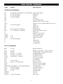
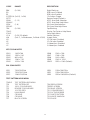
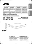
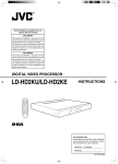
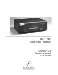
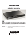
DVP1080MF
HD Digital Video Processor
Interim Installation and Operation Manual
IMPORTANT: THE DVP1080MF OFFERS MANY SETUP OPTIONS TO INSURE PROPER
INTEGRATION WITH SOURCES AND DISPLAY DEVICES. PLEASE READ THIS COMPLETE
MANUAL TO ENSURE PROPER INSTALLATION AND OPERATION. ANSWERS TO MOST
TECHNICAL QUESTIONS CAN BE FOUND HERE.
INSTALLERS:
Please review this manual carefully before contacting Technical Support.
PRODUCT OWNERS: Please contact your authorised Meridian/Faroudja dealer for product or
installation questions.
This page intentionally left blank
Important
Safety Instructions
•
•
•
•
•
•
•
•
•
•
•
•
•
•
WARNING: TO REDUCE THE RISK OF
FIRE OR ELECTRIC SHOCK, DO NOT
EXPOSE THIS APPARATUS TO RAIN OR
MOISTURE
Read these instructions.
Keep these instructions.
Heed all warnings.
Follow all instructions.
Do not use this apparatus near water.
Clean only with dry cloth.
Do not block any ventilation openings.
Install in accordance with the manufacturer’s
instructions.
Do not install near any heat sources such
as radiators, heat registers, stoves, or other
apparatus (including amplifiers) that produce
heat.
(North America) Do not defeat the safety
purpose of the polarized or grounding-type
plug. A polarized plug has two blades with one
wider than the other. A grounding type plug
has two blades and a third grounding prong.
The wide blade, or the third prong are provided
for your safety. If the provided plug does
not fit your outlet, consult an electrician for
replacement of the obsolete outlet.
Protect the power cord from being walked on
or pinched particularly at plugs, convenience
receptacles, and at the point they exit from the
apparatus.
Only use attachments/accessories specified by
the manufacturer.
Use only with the cart, stand,
tripod, bracket, or table specified
by the manufacturer, or sold with
the apparatus. When a cart is
used, use caution when moving
the cart/apparatus combination to avoid injury
from tip-over.
Unplug the apparatus during lightning storms
or when unused for long periods of time.
Refer all servicing to qualified service personnel.
Servicing is required when the apparatus has
been damaged in any way, such as powersupply cord or plug is damaged, liquid has
been spilled or objects have fallen in to the
apparatus, the apparatus has been exposed to
rain or moisture, does not operate normally, or
has been dropped.
This apparatus has been designed with Class 1
construction and must be connected to a
mains socket outlet with a protective earthing
connection (the third grounding pin).
To avoid overheating
• Leave at least 10cm around the equipment to
ensure sufficient ventilation.
Do not position the product:
• In direct sunlight.
• Near heat sources, such as a radiator.
• Directly on top of heat producing equipment,
such as a power amplifier.
• On a soft surface, such as a carpet, which
would obstruct the ventilation holes in the base.
The product normally runs warm to the touch.
FCC Information (USA Only)
CAUTION:
Changes or modifications not approved by
Meridian/Faroudja could void the user’s authority to operate the equipment.
FCC Warning
This equipment generates and can radiate
radio frequency energy and if not installed
and used correctly in accordance with
our instructions may cause interference
to radio communications or radio and
television reception. It has been type-tested
and complies with the limits set out in
Subpart J, Part 15 of FCC rules for a Class B
computing device. These limits are intended
to provide reasonable protection against such
interference in home installations. However,
there is no guarantee that interference will
not occur in a particular installation. If this
equipment does cause harmful interference
to radio or television reception, which can be
determined by turning the equipment off and
on, the user is encourage to try to correct the
interference by one or more of the following
measures:
Safety warnings
• Do not expose the product to dripping or
splashing.
• Do not place any object filled with liquid, such
as a vase, on the product.
• Do not place naked flame sources, such as
lighted candles, on the product.
To avoid interference
Do not position the product:
• Near strong magnetic radiation, such as near a
power amplifier.
• Near to a television, or where connecting cables
may be subject to or cause interference.
• Reorient or relocate the receiving antenna.
• Increase the separation between the equipment.
• Connect the equipment into an outlet on a
circuit different from that to which the receiver
is connected.
• Consult the dealer or an experienced radio/TV
technician for help.
TABLE OF CONTENTS
QUICK START INSTALLATION GUIDE.............................................................................................5-6
NOTE TO INSTALLERS......................................................................................................................7
INSTALLATION AND SETUP.........................................................................................................8-10
UNPACKING...........................................................................................................................8
MOUNTING............................................................................................................................8
OVERHEAT WARNING............................................................................................................8
CONNECTIONS...................................................................................................................8-9
SETUP MENU...........................................................................................................................10-12
DVP1080MF OPERATION.........................................................................................................12-15
FRONT PANEL.......................................................................................................................12
INFRARED REMOTE AND ON-SCREEN-DISPLAY................................................................13-15
RS232 COMMANDS................................................................................................................16-18
SPECIFICATIONS............................................................................................................................19
WARRANTY..................................................................................................................................20
Please review the installation and operations instructions in the following pages of this manual.
Each section includes application notes and suggestions that offer important additional information
to help insure a smooth installation and a happy customer.
The Faroudja section of the Meridian web site, www.meridian-audio.com, contains manuals, RS232
information and FAQs to assist with installations.
Copyright © 2006 Meridian Audio Limited. No part of this document may be copied, photocopied, translated, or
reproduced to any electronic medium or machine readable form without prior consent, in writing, from Meridian. The
Faroudja name and logo, and ‘DCDi by Faroudja’ are registered trademarks of Genesis Microchip Inc. Specifications
subject to change without notice. All Rights Reserved.
The Faroudja DVP1080MF is covered by the following United States patents: 4,030,121, 4,179,705, 4,240,105,
4,262,304, 4,847, 681, 4,864,389, 4,876,596, 4,893,176, 4,916,526,4,967,271, 4,982,280, 4,989,090, 5,014,119,
5,025,312, 5,159,451, 5,237,414.
Faroudja equipment is manufactured by Meridian Audio Limited under licence from Genesis Microchip Inc. Country of
origin as specified on product label.
INSTALLATION BASICS
QUICKSTART INSTRUCTIONS
It is recommended that the entire manual be reviewed prior to installing video equipment. Here
are the basic steps to install the DVP1080MF. Due to the long list of available setup options for
the different sources and displays, it is important to review each component’s manual for proper
operation.
• In installations where there are multiple sources using the same connection on the DVP1080MF, an
external switcher should be used.
• S-Video is an alternate input to use with satellite, DVD and video game sources.
• A thermally-activated low-noise fan is included on the rear panel.
1 Install equipment: Make sure there is proper ventilation to avoid overheating. Double check all
projector/screen calculations for best performance. Avoid using keystone correction, if possible.
2 Connect Sources: Make sure source devices are set to output the correct signal type that matches the
installation (Digital vs Analogue, YPrPb vs S-video, etc).
3 Connect display: Make sure display device is set for the correct input signal type from the video
processor. Review the display’s scan rate table (found in the rear of the User Guide for most models) to
see what scan rates are supported. DVI cables must be rated for the scan rate/length being used. Up to
50ft, non-fibre cable is OK if rated to 1280x1024 for output resolutions of 1365x1024 and lower; for
1920x1080p, DVI cable must be rated to 1600x1200 for the length required.
4 Enter SETUP: Press the MENU button for 7 seconds to enter the SETUP menu. Set the output scan rate. Set the proper screen shape.
5 Display Device: Adjust Brightness and Contrast. Use adjustments in the DVP1080MF if they are not
available in the display.
QUICKSTART INSTRUCTIONS:
MENU STRUCTURE
SET: RGB INPUT SYNC
SYNC-ON-GREEN/COMPOSITE SYNC
SET: OSD
ON/OFF
ON-SCREEN-DISPLAY
INPUT –
INPUT
ASPECT RATIO
PROFILE RECALL PROFILE STORE
PICTURE –
BRIGHTNESS
CONTRAST
COLOUR
TINT DETAIL ADVANCED COLOUR
DISPLAY –
H-POSITION
V-POSITION BLANKING LEVEL L/R BLANKING T/B BLANKING
SET: DVI INPUT H SYNC
WIDE/NORMAL
SET: OSD TIMER
0-255 (30 DEFAULT)
SET: VFD TIMER
0-255 (30 DEFAULT)
SET: VFD TIMEOUT LVL
OFF/LOW
SET: RS232 ECHO
ON/OFF
SET: BAUD RATE
9600/19200/57600
SET: SCREEN TRIGGER
ON/OFF
SET: STORE NTSC PROFILE
STORE PROFILE 1-8
PATTERNS – TEST PATTERNS PATTERN SELECT
SET: STORE PAL PROFILE
STORE PROFILE 1-8
SETUP MENU (Default setting in Bold)
Displayed on Front-Panel Vacuum Fluorescent
Display – NOT OSD
SET: 1080I TO 1080P
ENHANCED/HIGH-BANDWIDTH MODE
SET: RESTORE FACTORY
PRESS STORE
SET: NTSC SCAN RATE
ADJUSTABLE (1080P DEFAULT)
SET: PAL SCAN RATE
ADJUSTABLE (1080P DEFAULT)
SET: SCREEN SHAPE
WIDESCREEN/WIDE 4:3/4:3
• ‘WIDE 4:3’ is also known as ‘4:3 LB’ or ‘Letterbox’
• WIDESCREEN corresponds to an aspect ratio of
16:9
SET: ANALOGUE BLACK LVL
0/7.5 IRE
SET: HD INPUT H-ADJ
0-50 (25 default)
SET: DVI INPUT LEVEL
DVI-VIDEO (16-235) /DVI-PC (0-255)
SET: INPUT ENABLE / DISABLE
SET FOR EACH INPUT
NOTE TO AUTHORISED
MERIDIAN/FAROUDJA INSTALLERS
Please review the installation and operations
instructions in the following pages of this
manual. Each part includes application
notes and suggestions that offer important
additional information to help insure a smooth
installation and a happy customer.
The Faroudja section of the Meridian web site
contains manuals, RS232 information and
FAQs to assist with installation.
www.meridian-audio.com
In this manual, bullets • indicate important
application notes and » indicates an
installation or operational suggestion.
While this manual generally uses British English
spellings, you may find that the product
displays American English spellings in some
cases, and these are also used in this manual
where a mode or message displayed by the
unit is described. These spellings should be
understood as equivalent.
Accessory Kit
supplied with DVP1080MF Processor
1 - Manual
1 - Remote (when processor purchased on its
own; in a projector/processor package, the
remote is with the projector)
1 - Rack Kit
1 - Power Cord
INSTALLATION AND SETUP
CONNECTIONS
OVERVIEW: Be sure to use high quality cables
for both sources and output signals. All video
and High Definition scan rates are processed
and converted to the selected output rate and
format.
Numbers refer to the diagram above.
UNPACKING
» Inspect product box and unit for any shipping
damage.
» Save product box in the event the unit needs to
be shipped in the future. Shipping the unit in a
generic box may void warranty.
1. S-VIDEO INPUT: Use for video games,
satellite and DVD sources if Component or DVI
outputs are not available.
MOUNTING
» Shelf or rack mountable (rack kit included).
• EXCESSIVE HEAT MAY CAUSE THE PROCESSOR
TO MALFUNCTION OR SHORTEN PRODUCT
LIFE. Follow regular installation rules for proper
ventilation.
• Be sure rack location has adequate ventilation.
Allow a minimum of 1U rack space (1.75in)
above and below unit for ventilation.
» Do not mount above power amps or other
equipment that may generate excessive heat.
2. DVI INPUT: Use with satellite or DVD
sources. The processor is always monitoring
the DVI input and output status and provides
information on the front panel VFD. The VFD
status screens are:
DVI: Input signal is supported
NO INPUT: No signal is detected.
DVI PASS-THROUGH: A VESA rate has been
detected and sent to the output unprocessed.
RATE NOT SUPPORTED: A VESA or non-video
rate has been detected but the selected output
is analogue RGB or YPrPb.
OVERHEAT WARNING
To help insure long term operation, the
processor has a built in heat sensor to monitor
the internal temperatures of the unit . There
are two warning levels that appear on the
front panel VFD (Vacuum Fluorescent Display).
• Input type is auto-detected. Supported video
rates for processing are 480i/480p, 576i/576p,
720p/1080i @ 50Hz/60Hz. VESA rates are sent
to PASS-THROUGH only.
» A DVI cable must be connected from the
processor to the display and the digital output
must be activated in the processor SETUP menu.
• With HDCP encrypted sources, it may take up to
15 seconds for the HDCP authorisation between
source and display to be acquired. The display
device must be HDCP compatible to view an
image.
» If a switcher is used, it must also be HDCP
compliant. HDCP acquisition problems may be
displayed as snow or a flashing image on the
screen.
• The DVI input levels and sync type must be
matched to the DVI source in the SETUP menu.
See Page 11 for details.
• Some DVD players may offer a better image
using the analogue YPrPb connections with
LEVEL 1 WARNING
HIGH TEMPERATURE
» The internal temperature is exceeding optimum
operating temperature.
• Steps should be taken to improve ventilation.
• The rear panel exhaust fan will activate.
LEVEL 2 WARNING
HIGH TEMPERATURE SHUTDOWN
»The internal temperature has exceeded safe
operating limits and the unit has shut down.
• Unplug the unit from the wall power to reset.
Once the unit has cooled down, normal
operation returns. Steps must be taken to
improve ventilation.
9. DVI OUTPUT: For use with compatible
digital displays that use single link DVI
connectivity.
the player set to 480i output. This allows the
DVP1080MF to do all the deinterlacing and
digital conversion.
3. COMPOSITE VIDEO INPUT: Use with
low quality sources such as VHS and security
cameras.
• With HDCP encrypted sources, it can take up to
15 seconds for the HDCP authorisation between
source and display to be acquired. The display
device must be HDCP compatible to get an
image.
• Older VHS decks and tapes may cause an
unstable image. A distorted image is normal
during FFW, RW and Pause. A Time Base
Corrector can be added to help stabilise the
image.
• Higher resolution displays require higher
quality DVI cables. Using cables not rated for
the resolution being used will result in images
with coloured sparkles and lines. Always verify
maximum resolution rating of the cable with
cable supplier.
For 1080p, fibre optic cables should be used
for lengths over 15ft (or any cable rated for
1600x1200 resolution. Check with cable
supplier).
4. YPrPb / RGsB INPUTS: Input type is autodetected. Supported video rates for processing
are 480i/480p, 576i/576p, 720p and 1080i @
50Hz/60Hz. (VESA 640x480 not supported)
• When using RGsB, be sure to check settings for
this input in the SETUP menu. See Page 11 for
details.
10/11. DB9F RS232 CONNECTORS: Use for
device control (10 ‘option’ connector) and
control system interface (11).
5. INFRARED RECEIVER: for use with external
IR receivers. (3.5mm, 3-pin, Tip = +, Sleeve =
Gnd, Ring NC)
• The SETUP menu offers selections for RS232
operation. See Page 11 for details.
• The left-hand ‘option’ connector (10) allows
control of some Faroudja projector switching
functions, eg power on/off and 50/60Hz frame
rates. Contact technical support for full details.
6. 12V TRIGGER CONNECTIONS: For use
with electronic screens and other devices
requiring a 12volt trigger sequence. This
connection can be programmed for on/off
operation in the SETUP menu or via RS232.
(12V @ 100mA Max. 3.5mm 2 pin connector,
Tip = +12V, Sleeve = Gnd)
12. AC POWER CONNECTOR Connect to a
stable 100-240 volt AC 50/60Hz power line.
• To avoid ground loops, a power conditioner for
the equipment rack is recommended.
• Static electricity can cause equipment problems.
Be sure installer is grounded to chassis or
equipment rack before connecting sources.
7 & 8. Some units may have connectors in
these positions. These are not used.
NOTES
SETUP MENU
• Many DVD players offer black level options
(sometimes called “Enhanced Blacks”). The
player should be left at default settings:
adjust level in the DVP1080MF.
• Only available when the Component input is
selected with a 60Hz source.
OVERVIEW: The SETUP Menu offers many
selections to optimise the processor for
installation. Be sure to completely review the
menu items and application notes to insure
proper operation.
SET: HD INPUT H-ADJUST
0-50 (25 Default)
Adjusts the horizontal position of High
Definition sources (720p/1080i) to match the
horizontal position from Standard Definition
sources.
PRESS THE MENU KEY ON THE REMOTE
FOR 7 SECONDS TO ENTER SETUP MENU
• First align the proper image size and position on
the display using a test pattern from a DVD. Use
the H/V, L/R and sizing controls in the display
device, if available. Use the H/V adjustments in
the DVP1080MF OSD if the display does not
offer them. Then switch to the HD source and
adjust the HD INPUT H-ADJUST to match.
• Available only when a 1080i/720p signal is
detected. Not available in HIGH BANDWIDTH
mode
» The input for the HD source must be selected in
order to make the HD H-ADJUSTMENT.
» Some display devices offer minimal image
adjustments when using the DVI inputs.
» Some HD satellite receivers offer H-adjustments.
Those can also be used in conjunction with this
function to get the best results.
SETUP Menu functions are visible on the front
panel, not on the On-Screen-Display. Use the
directional buttons on the remote to navigate.
Defaults are shown in Bold below.
SET: NTSC SCAN RATE
This sets the output rate when a 60Hz source
is auto-detected.
• Press STORE TWICE (2X) to enter the new scan
rate. Store different output rates as Profiles. See
Storing Profiles on pages 11/12.
• Be sure to review the display device manual to
determine which output rate to choose.
SET: PAL SCAN RATE
This sets the output rate when a 50Hz source
is auto-detected.
SET:DVI INPUT LEVEL
DVI-VIDEO(16-235) / DVI-PC(0-255)
Sets the correct input signal level to match the
DVI input source.
• Press STORE TWICE (2X) to enter the new scan
rate. Store different output rates as Profiles. See
Storing Profiles on pages 11/12.
• Many digital displays have limited support of
50Hz signals. Be sure to check with the display
device’s manual to determine the proper output
rate.
• 0-255 is typical for digital display devices
inputs (the processor output is 0-255), 16-235
is typical for video sources. However, not all
sources follow the rules. If the processor DVI
input level is set to 0-255 but the source is 16235, the image will lack dynamic range.
• To test what the output is from the source,
put up a 10 step gray scale pattern from a test
pattern DVD. 16-235 and 0-255. The correct
setting is when all 10 bars are visible and evenly
lit. An incorrect setting will produce an image
that either looks dull or the brightest and
darkest bars are missing (clipping).
SET: SCREEN SHAPE
WIDESCREEN / WIDE-4:3 / 4:3
Set Screen shape to match the aspect ratio of
the display device.
• Select Wide-4:3 (4:3 Letterbox) when using a
4:3 native projector on a 16:9 screen.
• When using a 4:3 projector and anamorphic
lens on a 16:9 screen, select Widescreen.
• Screen shape defaults to AUTO when in HIGH
BANDWIDTH mode
0-255 Source + 16-235 Setting = Image too bright
16-235 Source + 0-255 Setting = Dull Image
• Only available when DVI input is selected
SET: ANALOGUE BLACK LEVEL
0 / 7.5IRE
Sets correct black level for YPrPb DVD sources.
INPUT ENABLE / DISABLE
Each input can be enabled or disabled
depending on the installation. Deactivating
10
unused inputs helps to streamline operation.
Each input is listed in the SETUP menu for
control: VIDEO-S/VIDEO-RGB-YCrCb-DVI
SET: BAUD RATE
9600/ 19200 / 57600
Sets the RS232 communication baud rate.
• If all inputs are disabled, Composite becomes
the default input
SET: SCREEN TRIGGER
OFF / ON
Allows programming of 12volt external trigger
to control accessories such as screens and
motorized lenses. OFF sets the 12v to NOT
turn on when the unit is powered up. ON sets
the 12v to turn ON. Store each command as a
profile to select using the remote or use RS232
commands.
SET: RGB INPUT SYNC
SYNC-ON-GREEN / COMPOSITE SYNC
Sets the sync type for the RGB input.
• Composite sync option should be selected when
using PAL RGB.
• Only available when RGB input is selected and
not in HIGH BANDWIDTH mode
SET: 1080i TO 1080P
ENHANCED / HI-BANDWIDTH
Sets how 1080i signals will be processed
when the output rate is set to 1080p only.
HI-BANDWIDTH mode has full bandwidth
processing with limited image adjustments
(Brightness/Contrast/Colour). ENHANCED
mode offers full image adjustment control at a
slightly reduced bandwidth.
SET: DVI INPUT H SYNC
NORMAL / WIDE
Sets the DVI sync position. With some
nonstandard DVI sources, selecting WIDE
will correct improper sync timing (seen as a
horizontal image shift).
• Only available when the DVI input is selected, a
video-HD rate is detected.
• This function only applies to displays with a
native resolution of 1920x1080p and with the
DVP1080MF set to the 1080p output scan rate.
Do not run 1080p scan rate on displays not
rated for such a high scan rate.
• Colour adjustment is only available when using
the YPrPb input.
SET:OSD
ON / OFF
Determines visibility of On-Screen-Display.
SET: OSD TIMER
0-255 (30 DEFAULT)
Sets how long the OSD will be visible after an
operation
0=OFF, 255=ALWAYS ON
SET: STORE NTSC PROFILE
STORE PROFILE 1-8
Stores all current settings for 60Hz sources (30
different parameters) to the profile number
selected in the NTSC memory bank
SET: VFD TIMER
0-255 (30 DEFAULT)
Sets how long the front panel Vacuum
Fluorescent Display (VFD) stays at full
brightness after an operation.
0=OFF, 255=ALWAYS ON
TO STORE DATA IN A PROFILE:
1 MAKE ALL ADJUSTMENTS AND
SETTINGS DESIRED IN THE SETUP MENU.
SET: VFD TIMEOUT LVL
Sets the brightness level of the front panel VFD
after the timer period has elapsed.
OFF/LOW
2 SELECT THE PROFILE NUMBER, THEN
PRESS STORE.
3 PROFILES CAN BE RECALLED USING THE
REMOTE CONTROL AND THE OSD.
SET: RS232 ECHO
ON / OFF
Determines whether command echoes are sent
back to the RS232 control device. See pages
17-18 for RS232 codes.
» Profiles can be recalled with the IR remote
using the OSD or via RS232. Profiles can also
be stored using the OSD which will over-write
Profiles stored here and vice-versa.
11
DVP1080MF OPERATION
SET: STORE PAL PROFILE
STORE PROFILE 1-8
Stores all current settings for PAL sources (30
different parameters) to the preset number
selected. See STORE NTSC for more details.
Each time the processor is powered up, it will
go through an initialising power-up sequence.
FRONT PANEL CONTROLS
(see illustration opposite)
• The processor auto-detects the input refresh
rate (60Hz/50Hz) and recalls Profiles stored for
that rate. 60Hz Profiles cannot be recalled while
viewing 50Hz sources and vice-versa.
RESET: In the event of a processor firmware
lockup, insert a small paper clip into opening
to reset. Stored profiles and system settings
will not be erased.
SET: RESTORE FACTORY
PRESS STORE
Resets processor firmware to original factory
levels.
• Unplugging the unit from its power source will
accomplish the same task.
• Only use this command if processor completely
locks up and other troubleshooting steps do not
solve the problem.
• Before using this option, try first unplugging
unit from power (or push a paper clip into the
small opening on the front panel). This will
often clear software lockups, and does not
erase settings.
POWER: Press to turn ON unit (LED Green),
press again to put unit in STANDBY (LED Red)
• All settings are stored in nonvolatile memory so
a power loss will not result in loss of settings.
IR WINDOW: Location of IR sensor for remote
control and IR remote systems
VFD (VACUUM FLUORESCENT DISPLAY):
Provides information on the status of the
processor. The readout will match what is
being controlled via the OSD. It also provides
readout of the SETUP menu functions and unit
warnings.
• The SETUP menu is only visible via the frontpanel VFD
ON-SCREEN DISPLAY (OSD)
There are four OSD menu pages: INPUT,
PICTURE, DISPLAY, PATTERNS.
INPUT: INPUT, ASPECT RATIO, PROFILES
PICTURE: BRIGHTNESS, CONTRAST, COLOR, TINT, DETAIL, ADVANCED COLOR CONTROL
DISPLAY: IMAGE POSITION, IMAGE BLANKING
PATTERNS: TEST PATTERN ON/OFF, SELECT
The remote control is used to access these
menus.
12
DVP1080MF FRONT PANEL
INFRARED REMOTE CONTROL
The DVP1080MF offers simple control of
picture adjustments via an on-screen menu,
controlled by the multi-function remote
control supplied.
Select projector
Select processor
DVP
On
DILA
Off
REMOTE BUTTON OPERATION
Store
Profile
Preset
DEVICE SELECT BUTTONS
Press the [DVP] button to select the processor
before attempting to control it. If you have a
Meridian projector you can press the [DILA]
button before addressing it.
Enter
Bypass
Menu
Exit
YCrCb
DVI
Video
ON & OFF BUTTONS
Press the [ON] button to turn on the unit, press
the [OFF] button to enter the standby mode.
Anamorphic
Colour
INPUT SELECT
Press the desired button to have direct access
to the different inputs.
• When [BYPASS] is selected, sources connected
to the DVI input will be sent to the DVI output
unchanged by the processor.
S-Video
RGB
4:3
Letterbox
Tint
Detail
3
1
2
Pattern
Focus
4
5
7
8
Hide
Zoom
Bright.
0
Backlit
6
T
W
9
Printed in White
Test
Cont.
Light
» An alternative approach is to select the input
using the On-Screen-Display: Press [MENU]
+ select INPUTS + use the [LEFT / RIGHT]
directional buttons to change inputs.
» The SETUP menu has a setting for deactivating
unused inputs. If an input is deactivated, it will
not be visible on the OSD, and the front panel
VFD will report INPUT NOT AVAILABLE if the
direct access button is pressed on the remote.
Backlit panel
• After pressing the [PROFILE] button, then
quickly press a number button [1-8] to recall the
desired profile.
DIRECTIONAL BUTTONS
Press [MENU] to access the OSD. Press again
to deactivate. Use the DIRECTIONAL keys to
navigate through the OSD options.
» An alternative method is to press the [PROFILE]
button then use the [LEFT/RIGHT] buttons on
the remote to select the desired Profile on the
OSD, then press [STORE] to select.
• To move to different OSD menu pages, press
[MENU], then [UP/DOWN] until the top triangle
turns yellow, then [RIGHT/LEFT]. A new MENU
page will appear as they are selected.
STORE BUTTON
Press to store changes or selections when
selecting the output scan rate or storing and
recalling Profile numbers. Profiles store 30
different image parameters.
PROFILE BUTTON
Press to recall Profiles that have been stored in
the unit.
13
STORING PRESETS USING THE OSD
1. Make all the desired image changes.
2. Using the DIRECTIONAL keys, go to the
INPUT menu.
3. Highlight the Profile number to store in.
4. Press the [STORE] button on the remote.
TINT BUTTON
Adjust for accurate tint.
• Tint adjust is only available with Composite or
S-Video sources.
» If the image colour still seems off balance
with the Tint set correctly, the gray scale of
the display may need adjusting. Contact your
installer for assistance. Suggested test pattern:
SMPTE colour bars using a blue filter.
» Profiles can also be stored in the SETUP menu.
Profiles stored using the OSD will override
Profiles stored via the SETUP menu AND viceversa.
DETAIL BUTTON
Adjusts the amount of enhancement in the
image.
IMAGE ADJUSTMENTS: Adjusting picture
levels can be done by pressing a direct access
button such as [CONT.] and then pressing a
three digit number on the NUMBER PAD or by
using the OSD and directional arrows to move
the adjustment sliders on the OSD.
Proper enhancement levels should add
subtle improvements in detail. Too much
enhancement will produce fake looking edges
and ringing. The higher quality the source,
typically, the less enhancement required.
• It is recommended that Brightness and Contrast
be adjusted in the display device first, if
possible, then adjust for individual movies or
channels using the DVP1080MF.
• A properly adjusted image is key to a good
picture. For each installation, the processor
should be calibrated for the sources using
reference test patterns whenever possible.
The following section will list a suggested test
pattern to use to get the best results.
»If a digital source (eg a poorly transferred DVD
or a very compressed satellite channel) has
excessive compression artifacts, reducing the
detail level can help to make the artifact less
visible.
• Suggested test pattern: DVD movie with a close
up of a face in still frame. Adjust so the face has
detail but the edges do not look fake (such as
along the bridge of the nose).
BRIGHT. BUTTON
Adjusts the darkest areas of the screen.
ASPECT RATIO BUTTONS
Each selects the proper aspect ratio of the
source being viewed.
» Adjust so the shadows are as dark as possible
but subtle details are still visible (such as seeing
the wrinkles in a dark suit on a person standing
in the shadows). Suggested test pattern: PLUGE
• The proper screen shape must be set in the
SETUP menu during initial installation in order
for these settings to function properly. See Page
10 for details.
CONT. BUTTON
Adjusts the lightest areas of the image.
» Adjust so the lightest areas are as bright as
possible but detail is still visible (such as seeing
the details in clouds on a sunny sky. Suggested
test pattern: 10 step gray scale.
ANAMORPHIC BUTTON
Selects proper aspect ratio for sources
formatted for wide screen displays (sometime
called “Enhanced for Widescreen” TVs).
» The image is too bright if the lightest bars in the
test pattern disappear or if they start to change
colour.
• DVD players must be set for 16:9 displays for
proper screen shape. See the DVD player setup
menu to adjust.
COLOUR BUTTON
Adjust to reproduce accurate colours.
LETTERBOX BUTTON
Selects proper aspect ratio for sources
formatted for the letterbox screen shape (nonanamorphic letterbox).
» Film-originated sources typically have more
subtle colour levels compared to videooriginated sources (sports, TV shows).
Suggested test pattern: SMPTE colour bars
(using blue filter).
» This mode can also be used with anamorphic
2.35:1 (Cinemascope) sources when combined
14
with an anamorphic lens on a 16:9 projector.
The benefit is the full resolution of the 16:9
display chip is used to create the active video.
This improves resolution and light output. The
12Volt trigger can be programmed to control
motorised lens attachments.
first, before setting side blanking. Blanking can
be stored in a Profile.
PATTERNS MENU PAGE
TEST PATTERNS ON/OFF: Activates the test
patterns circuit.
4:3 BUTTON
Selects proper aspect ratio for sources
formatted for 4:3 screen shape.
• When test patterns are activated, the image
level adjustments are fixed to reference levels
and cannot be changed. Use these patterns to
align or test your system. Many patterns are
designed for technician use only.
• On 16:9 displays, the side curtains of the image
will be blank. To protect displays from image
burn-in, the side curtains can be adjusted to any
level of gray from black to full white. Adjust the
level in the PICTURE OSD menu.
» For best results, all image adjustments should be
done with a test DVD from the DVD player and
patterns from the satellite box, if available. This
way the final image is adjusted for the complete
signal path from source, through the processor,
to the display.
» Do not view 4:3 images on 16:9 plasma or CRT
displays for extended periods of time with the
side curtains black. This can cause permanent
image burn-in. Image burn-in is not covered
under the warranty.
PICTURE MENU PAGE
LIGHT BUTTON
Activates the remote backlight for several
seconds.
ADVANCED COLOUR: The ‘Advanced Colour’
mode activates colour edge enhancement and
cross-colour suppression to improve the image
and remove certain video artifacts. This should
be set to Normal for most sources. With a few
movies that contain large amounts of colour
(such as animation), these circuits may cause
colour flickering. Set the mode to Bypass if this
occurs.
OTHER OSD IMAGE ADJUSTMENTS
DISPLAY MENU PAGE
IMAGE POSITION: Use to adjust the
horizontal and vertical position of the image.
• Many digital displays will not allow any image
adjustments when using DVI. Check with the
display manual to see if there is a service mode
to allow adjustments.
• Always use Image Adjust controls in the display
device first, if available.
» Shifting the image too far to the side can
cause the image to be lost or introduce moving
horizontal gray bars in the image. Use a safe
area test pattern to properly align image
position and size.
BLANKING LEVEL: Adjusts the gray level of
the side curtains when using 4:3 sources on a
16:9 display.
BLANKING (LEFT, RIGHT, TOP, BOTTOM):
Adjusts the amount of blanking for the edges
of the image to assist with proper image
sizing.
• Be sure image size and position is properly set
15
RS232 COMMANDS
RS232 OPTION CONNECTOR
The RS232 Option connector (10 in the diagram
on page 8) is used in the latest firmware revisions as a serial OUTPUT to control some display
functions. At present this control is limited to
handling power on/off and 50/60Hz switching
on Meridian Faroudja 1080p projectors. When
the DVP1080MF is powered up, it will command
the projector to switch on; and when powered
down, it will also power-down the projector.
Similarly, the DVP1080MF will switch the projector to 50/60 Hz operation depending on the
active input source. Contact Meridian Technical
Support for details on implementing this function, as additional features may become available
in due course.
The ‘dvp’ Header, followed by a comma (no
space), is used to delimit the Header from the
Command. The following is an example, using
Windows HyperTerminal, for Power On using a
standard Modem Cable:
»
dvp,on [Enter]
([Enter] denotes a carriage return – pressing
the Enter key on the keyboard)
• The DVP1080MF goes through a 10 second
initializing process when the ON command
is sent. Do not send any commands for 10
seconds after sending the ON command.
RS232 CONNECTIONS
You may also issue simultaneous commands
by adding a comma to delimit each Function
Command prior to issuing the Carriage Return
Command.
dvp,x,a2,srn4[Enter]
(Control Syntax = Header, YCrCb
(Component Input), Anamorphic, Scan Rate
1280x720[carriage return])
»
Personal Computer (PC Control) Use the
standard Windows HyperTerminal program
to control the DVP-1080. You can use an
equivalent program on a Macintosh computer.
If an RS232 port is unavailable, many types
of USB/Serial converters will work. Select the
options listed below and utilize a standard
9-pin Modem Cable (not a null-modem
cable). Once connection has been established, type dvp,help and then press [Enter]. The
OPERATION COMMANDS available will then
be echoed back to your personal computer.
BPS
Data bits
Parity
Stop bits
Flow control
19200
8
None
1
None
AMX and Crestron control examples; including
their respective Carriage Return commands:
AMX
“’dvp,on’,13”
“’dvp,off’,13”
Crestron
dvp,on\r
dvp,off\r
16
RS232 CONTROL COMMANDS
CODE
RANGE
DESCRIPTION
OPERATION COMMANDS
A#
B# C# D# DVI EXT FST HELP K# OFF ON P# PM# R
ST STHLP STNP# STPP# T# V
X
Y
(0-2) 0=4x3,1=Letterbox, 2=Anamorphic Input Aspect Ratio
(0-100) 50 default Brightness
(0-100) 50 default Contrast
(0-15) 04 default Detail
DVI Input
Pass-through Input
Report Current System Status
Displays full list of commands for this unit
(0-220) 50 default Colour
Power OFF
Power ON
(0-8) [1-8=User, 0=Factory] Recall Profiles
(0-1) [0=Normal, 1=Bypass] Advanced Colour System
RGB input
Report Current Status
Display Setup Menu
(1-8) Store NTSC Profile
(1-8) Store PAL Profile
(0-100) 50 default Tint
Video Input
YCrCb Input
S-Video Input
SETUP COMMANDS
BB# (0-100) BL# (0-100) BLT# (6-255) BLV# (0=0IRE, 1 = 7.5 IRE) CR# (0=0-255 1=16-235) DHS# (0=NORMAL, 1=WIDE) DVID DVIE E# (1=On 0=OFF) EX# (0=SOG, 1=Comp Sync) EXTD EXTE HDPROC#(0=NORMAL, 1=HIGH BANDWIDTH HP# (0-50) 25 default IHA# (0-50) 25 default LB#
(0-100) OSDOFF OSDON OSDT # (0-255) 30 default Bottom Blanking
Border Curtain Level - black to white
VFD Backlight Timer on front panel
Analogue Black Level
DVI INPUT LEVEL
DVI INPUT H SYNC
DVI Input Disabled
DVI Enabled
RS-232 ECHO
RGB Input Sync
PassThru Input Disabled
PassThru Input Enabled
HD processing
Horizontal Position
HD Input Adjust
Left Blanking
OSD Off
OSD On OSD Timer
17
CODE
RANGE
DESCRIPTION
RB# RD RE SCRTRG#
SETFT SRN#
SRNHLP SRP# SRPHLP TB# TPHLP STHLP VP # W# XD XE YD YE (0-100) (0=Off, 1=ON) (1-12) (1-6) (0-100) (0-20) 25 default (0=4:3, 1=Widescreen, 2=Wide 4:3/LB) Right Blanking
RGB Input Disabled
RGB Input Enabled
12v Screen Trigger
Restore Factory Defaults
NTSC Scan Rate Selection
NTSC Scan Rate Help Menu
PAL Scan Rate Selection
PAL Scan Rate Help Menu
Top Blanking
Display Test Pattern Help Menu
Setup Help Menu
Vertical Position
Aspect Ratio
YCrCb Input Disabled
YCrCb Input Enabled
S-Video Input Disabled
S-Video Input Enabled
NTSC SCAN RATES
SRN1 SRN2 SRN3
SRN4 SRN5 1400X788 1920 x 540 800 x 600 1280 x 720 1024 x 768 SRN6 SRN7 SRN8 SRN9 SRN12 1280 x 768
1366 x 768
1440 x 960
1280 X 1024
1920 x 1080 (Default)
SRP4
SRP5
SRP6
1024x768/75Hz
1024x768/100Hz
1920x1080/50Hz (Default)
PAL SCAN RATES
SRP1
SRP2
SRP3
720x576/50Hz 720x576/100Hz
1280x720/50Hz TEST PATTERN HELP MENU
TPHELP TP0 TP1 TP2 TP3 TP4 TP5 TP6 TP7 TEST PATTERN HELP MENU
TEST PATTERN OFF 100% COLOUR BARS REVERSE COLOUR BARS 10 STEP GREY
LUMA RAMP CB RAMP CR RAMP
BLACK SCREEN TP8 GREEN SCREEN
TP9 RED SCREEN
TP10 BLUE SCREEN
TP11 CONVERGENCE TP12 ACTIVE BORDER
TP13 SMPTE PATTERN
TP14 WHITE WINDOW TP15 PLUGE
18
DVP1080MF SPECIFICATIONS
Processing
10-bit signal path
1080i deinterlacing with MADI (Motion Adaptive DeInterlacing), 3:2 pulldown (60Hz operation)
and 2:2 pulldown (50Hz operation)
High Bandwidth Mode: full resolution 1920x1080p (Straight deinterlacing without scaling)
Enhanced mode: 1080i converted to 1280x720 resolution then scaled to the selected output rate
Inputs
Format Composite (BNC) S-Video (4-pin DIN) Component (BNC) 480i/480p/720p/1080i RGB (BNC) 480i/480p/720p/1080i DVI Input NTSC/PAL
1v pp
Y - 1v pp, C - 700mv pp
Y - 1v pp (SMPTE)
Cr - 700mv pp
Cb - 700mv pp
Comp. Sync - 1v pp
RGB - 700mv pp
DVI - I (female) Digital Only (0-255/16-235)
Output (Progressive)
Digital Video Interface: DVI - I (female) digital only 0-255
HDCP Compliant
Operational Temperature Range Power Supply Power Consumption Dimensions: Weight: 41°F to 104°F (+5°C to + 40°C)
with internal temperature warning
100-240VAC 50/60Hz Auto Ranging
35 watts
1.75in H x 17in W x 12.5in D
(Depth includes rear BNC)
Allow 3in in rear for cables
14 lbs
Specifications and features subject to change without notice
19
WARRANTY STATEMENT
Meridian Audio Limited (“Meridian”), manufacturing Faroudja products under licence from Genesis
Microchip Inc., warranties that its products will substantially conform to published specifications, subject
to the terms and conditions below. These warranties are limited to the first purchaser of the products
(“Purchaser”) for the period listed below from the date of sale.
Video Processors: Two (2) years limited parts and labour
DVD Drives: One (1) year limited parts and labour
Projectors: DILA-Based products: Two (2) years limited parts and labour (Image burn-in is not covered)
These limited warranties are contingent upon proper use and installation and do not apply to products
damaged as a result of accident, misuse, neglect, alteration, improper installation, unusual physical or
electrical stress or unauthorised repair.
Image burn-in on display devices is not covered under warranty. See individual product warranty statement
for warranty limitations. All warranty claims should be made at the place of purchase.
No products may be returned to Meridian without its consent. If requested by Meridian, Purchaser must
provide proof of purchase and return defective products to Meridian with the appropriate Return Material
Authorisation (RMA) completed, a Meridian RMA number assigned and transportation charges prepaid.
Warranty may be void if unit is not returned to Meridian Service in the original shipping carton.
Should a product fail to conform to the warranty above, then Meridian shall, at Meridian’s sole option,
(i) repair the non-conforming product or portion thereof, provided that the product is returned to Meridian
within the warranty period in accordance with the return procedures set forth above, or (ii) provide
Purchaser with replacement for the non-conforming product or portion thereof.
The preceding sentence states Meridian’s entire liability and Purchaser’s exclusive remedy with respect to
breach of the warranty.
THE FOREGOING WARRANTIES ARE IN LIEU OF ALL WARRANTIES EXPRESSED, IMPLIED OR STATUTORY,
REGARDING THE PRODUCTS, AND ALL IMPLIED WARRANTIES, INCLUDING, WITHOUT LIMITATION,
ANY IMPLIED WARRANTIES OF MERCHANTABILITY OR FITNESS FOR A PARTICULAR PURPOSE AND ANY
OTHER WARRANTY OBLIGATIONS ON THE PART OF MERIDIAN OR GENESIS MICROCHIP INC. IN NO
EVENT WILL MERIDIAN OR GENESIS MICROCHIP INC. BE LIABLE FOR LOSS OF PROFITS OR GOODWILL,
OR DIRECT, INDIRECT, INCIDENTAL, CONSEQUENTIAL OR SPECIAL DAMAGES OF ANY KIND, HOWEVER
CAUSED, WHETHER BY MERIDIAN’S BREACH OF WARRANTY OR BY MERIDIAN’S SOLE OR CONCURRENT
NEGLIGENCE OR OTHERWISE.
Meridian may change product specifications and warranty policy at any time without notice. The Warranty
policy outlined above effective September 1, 2003. Our most current warranty policy can be viewed on-line
at www.meridian-audio.com.
20
This page intentionally left blank
21
Meridian Audio Limited
Latham Road,
Huntingdon, Cambridgeshire PE29 6YE
United Kingdom
Tel +44 (0) 1480 445678
Fax +44 (0) 1480 445686
Web: www.meridian-audio.com
Meridian America Inc
8055 Troon Circle, Suite C
Austell, Atlanta GA 30168-7849
USA
Tel +1 (404) 344 7111
Fax +1 (404) 346 7111
Faroudja is a trademark of Genesis Microchip Inc.
Other trademarks are the property of their respective owners.
Email: info@meridian-audio.com
DVP1080MFIman v1.2 • REƒ • 20060509