1
C H A P T E R
7
NPE-G1 and NPE-G2 Installation and
Configuration Information
This chapter provides information on installing and configuring the NPE-G1 and NPE-G2 and contains
the following sections:
Note
•
Preparing for an Upgrade, page 7-2
•
Copying the Configuration File, page 7-4
•
Removing the Network Processing Engine, page 7-7
•
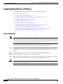
Installing the NPE-G1 or NPE-G2, page 7-18
•
Enabling the Second Processor on the NPE-G1, page 7-45
•
Copying the Saved Configuration to NVRAM, page 7-51
•
Auxiliary and Console Port Information, page 7-54
•
Configuring the Native Gigabit Ethernet Interfaces, page 7-54
•
Using show Commands to Check the Installation, page 7-57
•
Upgrading the Cisco IOS Image and the Boot Helper (Boot Loader) Image, page 7-60
•
Upgrading ROMmon on the NPE-G1 or NPE-G2, page 7-61
•
Upgrading FPGA on the NPE-G2, page 7-65
•
Troubleshooting the Upgrade, page 7-63
•
Troubleshooting the NPE-G1 or NPE-G2, page 7-65
•
Fiber Optic Cleaning Information, page 7-65
The Cisco 7200 VXR and Cisco uBR7246VXR routers use different models of the NPE-G1 processor.
For the Cisco 7200 VXR, order the NPE-G1 or NPE-G1= product. For the Cisco uBR7246VXR router,
order the UBR7200-NPE-G1 or UBR7200-NPE-G1= product. Unless otherwise indicated, all references
in this chapter to the NPE-G1 refer to both models.
Network Processing Engine and Network Services Engine Installation and Configuration
OL-4448-08
7-1
Chapter 7
NPE-G1 and NPE-G2 Installation and Configuration Information
Preparing for an Upgrade
Tip
Before you begin any removal or installation procedure, read Chapter 8, “Preparation for Installation.”
Also, for the NPE-G1, see the NPE-G1 Read Me First document, at the following URL:
http://www.cisco.com/en/US/products/hw/routers/ps341/prod_installation_guide09186a00805e396a.ht
ml
For the Cisco uBR7200-NPE-G1, see the Cisco uBR7200-NPE-G1 Read Me First document, at the
following URL:
http://www.cisco.com/en/US/products/hw/cable/ps2217/prod_pre_installation_guide09186a008017bde
6.html
Preparing for an Upgrade
Note
Cisco IOS Release 12.2 changed the behavior of the ROM monitor (ROMmon) during the bootup
sequence. See Chapter 10, “Boot Changes in Cisco IOS Release 12.2” for more information.
Upgrading to the NPE-G1 or NPE-G2 is a different procedure than previous processor upgrades because
of the following considerations:
•
The NPE-G1 and NPE-G2 contain an I/O controller, which includes the bootflash and NVRAM
memory. After you install the NPE-G1 or NPE-G2 in a chassis, you can no longer access the
bootflash and NVRAM on the I/O controller. You therefore must make the existing Cisco IOS
software image and configuration files available to the NPE-G1 or NPE-G2, either by putting these
files on a CompactFlash Disk or on a TFTP server.
•
The NPE-G1 and NPE-G2 include three Gigabit Ethernet interfaces. If you want to use these
interfaces to replace the Ethernet or Fast Ethernet interfaces on the existing I/O controller, you will
have to configure the new interfaces before they can be used to access the network. If you are also
removing the existing I/O controller, you will need to remove the configuration for its Ethernet or
Fast Ethernet interfaces.
Note
•
Note
The NPE-G2 provides a Fast Ethernet Management port, as well as three RJ-45 Gigabit
Ethernet ports.
The NPE-G1and NPE-G2 use Type 1 CompactFlash Disk memory instead of the Type 2 Flash Disk
memory used in existing I/O controllers. You must transfer any information currently saved on Flash
Disks to CompactFlash Disks so that it can be used after the upgrade to the NPE-G1 or NPE-G2.
If you are upgrading to an NPE-G2 from an NPE-G1, you do not need to do the following procedure.
To ensure a smooth upgrade, do the following procedure only if you are upgrading to an NPE-G1 or
NPE-G2 from an NPE-400 or earlier processing engine.
Network Processing Engine and Network Services Engine Installation and Configuration
7-2
OL-4448-08
Chapter 7
NPE-G1 and NPE-G2 Installation and Configuration Information
Preparing for an Upgrade
Before you install an NPE-G1 or NPE-G2 in an existing router and remove the existing processor and
I/O controller, do the following:
Step 1
Copy the configuration file from the existing router to a TFTP server, Flash Disk, or PC Card. See the
“Copying the Configuration File” section on page 7-4 for details.
Step 2
Modify the configuration file to accommodate the new Gigabit Ethernet interfaces on the NPE-G1 or
NPE-G2. If you are also planning to remove the I/O controller, also remove the configuration lines for
the Ethernet or Fast Ethernet interfaces on the I/O controller. See the “Configuring the Native Gigabit
Ethernet Interfaces” section on page 7-54 for guidelines.
Step 3
Copy the modified configuration file to a CompactFlash Disk that can be used on the NPE-G1 or
NPE-G2. If you are not planning on removing the existing I/O controller, you can do this by copying the
configuration to a Flash Disk, as described in Step 1, before you install the NPE-G1 or NPE-G2. Then
you can keep the Flash Disk in the I/O controller and copy it to a CompactFlash Disk in the NPE-G1 or
NPE-G2 after you have finished installing the NPE-G1 or NPE-G2.
If you are planning on removing the existing I/O controller, you can copy the configuration file to a
CompactFlash Disk in the following ways:
•
Copy the configuration file to a TFTP server and then copy it to a CompactFlash Disk on an existing
NPE-G1 or NPE-G2.
•
Copy the configuration file to a Type 2 Flash Disk using the existing I/O controller, as described in
Step 2 of the “Copying the Configuration File to a Flash Disk or PC Card” section on page 7-4. Then
use a multi-function reader that accommodates both Type 1 CompactFlash Disk and Type 2 Flash
Disk memory cards to transfer the configuration file to the CompactFlash Disk.
•
Use a Type 1-to-Type 2 adapter to convert the CompactFlash Disk to the Flash Disk form factor.
Then insert the CompactFlash Disk and adapter into the existing I/O controller and copy the
configuration file to it, as described in Step 1.
Note
Step 4
The CompactFlash Disk must be formatted before you can write any files to it. The
CompactFlash Disk shipped with the NPE-G1 or NPE-G2 is already formatted, but a spare
CompactFlash Disk must be formatted using the format command. Do not format the
CompactFlash Disk in a PC or other workstation because the router cannot use Flash Disks that
are formatted by other computers. After the CompactFlash Disk is properly formatted, however,
you can write to it using any PC or workstation that recognizes Type 2 CompactFlash Disk
memory.
(Optional) Copy the proper Cisco IOS software image (see Table 8-4 on page 8-4) to the CompactFlash
Disk, using the same technique you used to copy the configuration file in Step 3. You do not need to
perform this step if you plan to boot the router from a TFTP server, but you must add the proper boot
configuration command to the configuration file when you modify it in Step 2.
Network Processing Engine and Network Services Engine Installation and Configuration
OL-4448-08
7-3
Chapter 7
NPE-G1 and NPE-G2 Installation and Configuration Information
Copying the Configuration File
Copying the Configuration File
Caution
Before powering down the router to install the NPE-G1 or NPE-G2, you must save the current
configuration to a Flash Disk, PC Card, Trivial File Transfer Protocol (TFTP) file server, or PC before
you install the NPE-G1 or NPE-G2, or the configuration will be lost and you will have to manually
re-enter your configuration.
Cisco IOS looks to the NPE-G1 or NPE-G2 NVRAM for the startup running configuration, because the
NPE-G1 or NPE-G2, by default, stores the running configuration, whether or not an I/O controller is
installed with the NPE-G1 or NPE-G2.
The following sections provide instructions for copying the file to a Flash Disk, PC Card, or TFTP server,
and for copying it manually using a terminal program on a PC:
•
Copying the Configuration File to a Flash Disk or PC Card, page 7-4
•
Copying the Configuration File to a TFTP Server, page 7-5
•
Copying the Configuration File Using a PC, page 7-7
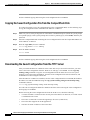
Copying the Configuration File to a Flash Disk or PC Card
Use the following instructions for copying the router configuration file to a Flash Disk or PC Card.
Caution
If the NPE-G1 or NPE-G2 will be installed in a router with either a C7200-I/O-GE/E or
C7200-I/O-2FE/E I/O controller, copy your running configuration to a Flash Disk, not a PC Card. PC
Cards are not supported on these I/O controllers when an NPE-G1 or NPE-G2 is present. If you copy the
running configuration to a PC Card with these I/O controllers present, you will not be able to retrieve
the running configuration after the NPE-G1 or NPE-G2 is installed.
Step 1
Insert the Flash Disk or PC Card into I/O controller PC Card slot 0. If slot 0 is full, use slot 1. If you
need to format the Flash Disk, go to Step 2. If the Flash Disk is already formatted, go to Step 3.
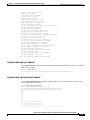
Step 2
Use the format disk0: command to format a Flash Disk in slot 0. Use the format disk1: command to
format a Flash Disk in slot 1. If you are using a PC card, use slot0 or slot1 as part of the command.
System# format disk0:
Format operation may take a while. Contineu: [confirm]
Format operation will destroy all data in ‘disk0:’. Continue? [confirm]
Format :Drive communication and 1st Sector Write OK...
Writing Monlib sectors
..........................................................................................
Monlib write complete
Format:All system sectors written. OK...
Format:Total sectors in formatted partitioin:81760
Format:Total bytes in formatted partition:49861120
Format:Operation completed successfully.
Format of disk0:complete
The Flash Disk is now formatted and ready to use in the system on which you formatted it.
Network Processing Engine and Network Services Engine Installation and Configuration
7-4
OL-4448-08
Chapter 7
NPE-G1 and NPE-G2 Installation and Configuration Information
Copying the Configuration File
Step 3
Make sure you are at the privileged level of the EXEC command interpreter (check the system prompt
for a pound sign [#]). If the system prompt does not have a pound sign (#), enter enable, and then your
password.
Step 4
Enter the show running-config command to display the router’s running configuration. Ensure that the
configuration information is complete and correct. If it is not, use the configure command to add or
modify the existing configuration. Then enter the copy running-config command. If you have a Flash
Disk 0 or 1, use disk0 or disk1 as part of the command. If you are using a PC Card, use slot0 or slot1
as part of the command.
Step 5
To copy the running configuration file to the Flash Disk or PC Card, enter the copy running-config
disk0: filename or copy running-config slot0: filename command:
System# copy running-config disk0: filename
You have finished copying the running configuration file to the Flash Disk or PC Card.
Go to the “Removing the Network Processing Engine” section on page 7-7 for instructions on removing
the current network processing engine or network services engine and replacing it with the NPE-G1 or
NPE-G2.
Copying the Configuration File to a TFTP Server
Before copying the router configuration file to a TFTP file server, check the following items:
•
A console terminal is connected to the console port on the I/O controller or a Telnet session is
established to the router.
•
The router is connected to a network supporting a file server (remote host).
•
The remote host supports the TFTP application.
•
You have the name or address of the remote host.
Complete the following steps to copy the router’s configuration file to a remote host:
Step 1
Make sure you are at the privileged level of the EXEC command interpreter (check the system prompt
for a pound sign [#]). If the system prompt does not have a pound sign (#), enter enable, and then your
password.
Step 2
Use the ping command to check the connection between the router and the remote host.
Step 3
Enter the show running-config command to display the router’s running configuration. Ensure that the
configuration information is complete and correct. If it is not, use the configure command to add or
modify the existing configuration. Then enter the copy running-config startup-config command to
save the retrieved configuration in NVRAM. NVRAM uses lithium batteries to maintain its contents
when disconnected from power.
Note
Step 4
Refer to the appropriate software documentation listed in the “Related Documentation” section
on page iii for descriptions of the configuration options available for the system and individual
interfaces, and for specific configuration instructions.
Enter the copy startup-config tftp command. The EXEC command interpreter prompts you for the
name or IP address of the remote host that is to receive the configuration file. (The prompt might
include the name or address of a default file server.)
Network Processing Engine and Network Services Engine Installation and Configuration
OL-4448-08
7-5
Chapter 7
NPE-G1 and NPE-G2 Installation and Configuration Information
Copying the Configuration File
Router# copy startup-config tftp
Remote host []?
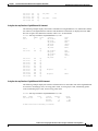
Step 5
Enter the name or IP address of the remote host. In the following example, the name of the remote host
is servername:
Router# copy startup-config tftp
Remote host []? servername
Translating "servername"...domain server (10.1.1.1) [OK]
Step 6
The EXEC command interpreter prompts you for the name of the file that will contain the configuration.
By default, the system appends -confg to the router’s name to create the new filename. Press Return to
accept the default filename, or enter a different name for the file before pressing Return. In the following
example, the default is accepted:
Name of configuration file to write [Router-confg]?
Write file Router-confg on host 10.1.1.1? [confirm]
Writing Router-confg.....
Step 7
Before the router executes the copy process, it displays the instructions you entered for confirmation. If
the instructions are not correct, enter n (no), and then Return to stop the process. To accept the
instructions, press Return, or y and then press Return; the system begins the copy process. In the
following example, the default is accepted:
Write file Router-confg on host 10.1.1.1? [confirm]
Writing Router-confg: !!!! [ok]
While the router copies the configuration to the remote host, it displays a series of exclamation points
(! ! !) or periods (. . .). The !!!! and [ok] indicate that the operation is successful. A display of . . . [timed
out] or [failed] indicates a failure, which would probably be because of a network fault or the lack of a
writable, readable file on the remote file server.
Step 8
Check the result of the copy process.
•
If the display indicates that the process was successful (with the series of exclamation points [! ! !]
and [ok]), the copy process is complete. The configuration file is safely stored in the temporary file
on the remote file server.
•
If the display indicates that the process failed (with the series of periods [. . .] as shown in the
following example), your configuration was not saved:
Writing Router-confg .....
Step 9
If your configuration was not saved, repeat the preceding steps, or select a different remote file server
and repeat the preceding steps. If you are unable to copy the configuration to a remote host
successfully, contact your network administrator or see the “Obtaining Technical Assistance” section
on page vii for instructions on contacting technical assistance.
This completes the procedure for copying the configuration file to a TFTP server. Proceed to the section,
“Removing the Network Processing Engine” section on page 7-7.
Network Processing Engine and Network Services Engine Installation and Configuration
7-6
OL-4448-08
Chapter 7
NPE-G1 and NPE-G2 Installation and Configuration Information
Removing the Network Processing Engine
Copying the Configuration File Using a PC
Complete the following steps to copy the router’s configuration file to text file on a PC connected to the
router’s console port.
Step 1
Connect a serial port on the PC to the router’s console port. Start a terminal program on the PC and
configure it for the same baud rate, parity, and stop-bits that the console port is using.
Step 2
Turn on the terminal program’s capture buffer so that it will save all output to a text file.
Step 3
Enter the show startup-config command in privileged EXEC mode to display the router’s startup
configuration.
Note
Refer to the appropriate software documentation listed in the “Related Documentation” section
on page iii for descriptions of the configuration options available for the system and individual
interfaces, and for specific configuration instructions.
Step 4
When the router has completed displaying the configuration, turn off the terminal program’s capture
buffer and save the configuration file to the disk on the PC.
Step 5
(Optional) Use a text editor on the PC to modify the configuration, as needed.
This completes the procedure for copying the configuration file to a PC. Proceed to the section,
“Removing the Network Processing Engine” section on page 7-7.
Removing the Network Processing Engine
Before you begin any removal or installation procedure, read Chapter 8, “Preparation for Installation.”
To install the NPE-G1 or NPE-G2, follow the instructions in this chapter for removal of an existing
network processing engine or network services engine and installation of the NPE-G1 or NPE-G2.
Note
If you are removing the I/O controller, and do not plan to replace it, you must install an I/O controller
blank panel, (Cisco Product Number IO-CONTROLR-BLANK=) in the I/O controller slot. See the
Input/Output Controller Replacement Instructions for information on removing an I/O controller and
installing an I/O controller blank panel.
If you are installing a Port Adapter Jacket Card, see the Port Adapter Jacket Card Installation Guide for
installation information.
Network Processing Engine and Network Services Engine Installation and Configuration
OL-4448-08
7-7
Chapter 7
NPE-G1 and NPE-G2 Installation and Configuration Information
Removing the Network Processing Engine
Ensuring Easy Access to the Router
If your Cisco 7200 VXR or Cisco uBR7246VXR router is installed in a standard 19-inch, 4-post or
telco-type rack, cables from other equipment in the rack might obstruct access to the rear of the router.
Also, rack power strips or other permanent fixtures may obstruct access to the router. Review the
following guidelines to ensure easy access to the rear of the router when it is installed in a rack. This is
particularly important because the NPE-G1 and NPE-G2 have interfaces that require cabling on the rear
of the router.
Note
The NPE-G2 is not supported on the Cisco uBR7246VXR router.
If the router is not installed in a rack, or if you already have clear access to the rear of the router, proceed
to the “Powering Down the Router and Disconnecting Input Power” section on page 7-8.
Use the following guidelines to ensure easy access to the rear of the router when it is installed in a rack:
Caution
•
Ensure that you have at least 3 to 4 feet (0.91 to 1.22 meters) of working space at the rear of the
router.
•
If cables from other equipment in the rack fall in front of the rear end of the router, carefully gather
the cables (using care not to strain or stress them) and use cable ties to anchor them away from the
rear of the router.
•
If access to the rear of the router is partially blocked by a power strip or some other permanent rack
fixture, detach the router from the rack and carefully slide it forward until there is enough clearance
to remove the power supply, the network processing engine, and the subchassis from the router.
Make sure that at least one other person is available to support the front of the router as you slide it out
from the rack and, if necessary, to continue to support it while you remove and insert the power supply,
network processing engine, or subchassis.
Powering Down the Router and Disconnecting Input Power
Complete the steps in the following sections to power down the router and disconnect input power.
Caution
This unit might have more than one power cord. To reduce the risk of electric shock, disconnect the two
power cords before servicing. Statement 83
Powering Down the Router
To power down a Cisco 7200 VXR or Cisco uBR7246VXR router, complete the following steps:
Note
Before powering down the router, use the copy running-config startup-config command to save the
router’s running configuration to a Flash Disk, PC Card, or TFTP server. If you do not, you will have to
manually reenter the configuration after you install the NPE-G1 or NPE-G2 and power on the router. See
the “Copying the Configuration File” section on page 7-4.
Network Processing Engine and Network Services Engine Installation and Configuration
7-8
OL-4448-08
Chapter 7
NPE-G1 and NPE-G2 Installation and Configuration Information
Removing the Network Processing Engine
Step 1
Facing the rear of the router, place the power switch on the power supply in the off (O) position. Repeat
this action if a second power supply is installed in the router.
Note
Step 2
Caution
When powering off the router, wait a minimum of 30 seconds before powering it on again.
Observe the following items:
•
The green OK LED on the power supply turns off.
•
The fans stop operating.
•
The LEDs on the I/O controller turn off.
•
The LEDs on the port adapters turn off.
When the power switch on a Cisco uBR7200 series power supply is turned to the off (O) position, the
power supply enters a reset cycle for 90 seconds. Wait at least 90 seconds before turning the power
switch back to the on (|) position. If you do not wait the full 90 seconds, the power supply does not
restart.
This completes the procedure for powering down the router. The following sections provide instructions
on disconnecting power from the Cisco 7200 VXR routers and Cisco uBR7200 routers:
•
Disconnecting AC-Input Power from a Cisco 7200 VXR Router, page 7-9
•
Disconnecting AC-Input Power from a Cisco uBR7246VXR Router, page 7-10
•
Disconnecting DC-Input Power from a Cisco 7200 VXR Router, page 7-11
•
Disconnecting DC-Input Power from a Cisco uBR7246VXR Router, page 7-13
Disconnecting AC-Input Power from a Cisco 7200 VXR Router
To disconnect AC-input power to a Cisco 7200 VXR router, complete the following steps:
Step 1
Unplug the input power cable from the power source.
Step 2
On a Cisco 7200 VXR router, push up on the cable-retention clip that secures the input power cable to
the router power supply.
Step 3
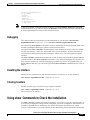
Unplug the other end of the input power cable from the power supply. See Figure 7-1.
Network Processing Engine and Network Services Engine Installation and Configuration
OL-4448-08
7-9
Chapter 7
NPE-G1 and NPE-G2 Installation and Configuration Information
Removing the Network Processing Engine
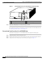
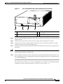
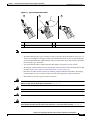
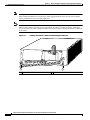
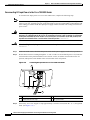
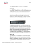
Figure 7-1
Disconnecting Power from a Cisco 7200 VXR Router AC-Input Power Supply
1
66415
2
NETWORK PROCESSING ENGINE-300
3
Step 4
4
1
AC-input receptacle
3
Power switch
2
Internal fans
4
AC-input power supply
Repeat Step 1 through Step 3 if a second power supply is installed.
This completes the procedure for disconnecting AC-input power from a Cisco 7200 VXR router. Go to
the “Removing the NPE or NSE-1” section on page 7-16.
Disconnecting AC-Input Power from a Cisco uBR7246VXR Router
To disconnect AC-input power to a Cisco uBR7246VXR router, complete the following steps:
Step 1
Unplug the input power cable from the power source.
Step 2
Push the cable-retention clip that secures the input power cable to the router power supply to the left.
Step 3
Unplug the other end of the input power cable from the power supply. See Figure 7-2.
Network Processing Engine and Network Services Engine Installation and Configuration
7-10
OL-4448-08
Chapter 7
NPE-G1 and NPE-G2 Installation and Configuration Information
Removing the Network Processing Engine
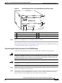
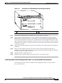
Figure 7-2
Disconnecting Power from a Cisco uBR7246VXR AC-Input Power Supply
4
66434
5
1
Step 4
2
3
1
AC-input receptacle
4
Network processing engine
2
Power switch
5
AC-input power supply
3
Handle
Repeat Step 1 through Step 3 if a second power supply is installed.
This completes the procedure for disconnecting AC-input power from a Cisco uBR7246VXR router. Go
to “Removing the NPE or NSE-1” section on page 7-16.
Disconnecting DC-Input Power from a Cisco 7200 VXR Router
To disconnect DC-input power from a Cisco 7200 VXR router, complete the following steps.
Warning
Before completing any of the following steps, and to prevent short-circuit or shock hazards, ensure
that power is removed from the DC circuit. To ensure that all power is OFF, locate the circuit breaker
on the panel board that services the DC circuit, switch the circuit breaker to the OFF position, and
tape the switch handle of the circuit breaker in the OFF position. Statement 332
Warning
When you install the unit, the ground connection must always be made first and disconnected last.
Statement 42
Step 1
At the rear of the router, check that the power switch on the power supply is in the off (O) position. (For
the Cisco 7200 VXR routers, see Figure 7-3.)
Step 2
Ensure that no current is running through the –V and +V leads. To ensure that all power is off, locate the
circuit breaker on the panel board that services the DC circuit, switch the circuit breaker to the off
position, and tape the switch handle of the circuit breaker in the off position.
Network Processing Engine and Network Services Engine Installation and Configuration
OL-4448-08
7-11
Chapter 7
NPE-G1 and NPE-G2 Installation and Configuration Information
Removing the Network Processing Engine
Step 3
Disconnect the –V and +V leads. You can leave the ground cable connected.
Step 4
For a Cisco 7200 VXR router, remove the cable tie that secures the –V, +V, and ground leads to the power
supply faceplate. Save the cable tie.
Note
The cable tie that accompanied your Cisco 7200 VXR router DC-input power supply can be
removed and replaced on the power supply without the use of a tool. If you secured the DC-input
power supply leads to the power supply faceplate using a different type of cable tie, use a wire
stripper to cut that cable tie from the power supply.
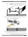
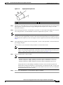
Figure 7-3
Disconnecting Power from a Cisco 7200 VXR Router DC-Input Power Supply
2
66431
1
networking xxxx engine
3
4
1
DC-input receptacle
3
Power switch
2
Internal fans
4
DC-input power supply
Step 5
Using a 3/16-inch flat-blade screwdriver, loosen the screw below the +V lead receptacle and pull the lead
from the connector. See Figure 7-3.
Step 6
Repeat this step for the –V lead and the ground lead.
Note
Step 7
The color coding of the DC-input power supply leads depends on the color coding of the DC
power source at your site. Typically, green or green and yellow are used for ground. Make certain
that the lead color coding you choose for the DC-input power supply matches the lead color
coding used at the DC power source.
Repeat Step 1 through Step 6 if a second power supply is installed.
This completes the procedure for disconnecting DC-input power from a Cisco 7200 VXR router. Go to
the “Removing the NPE or NSE-1” section on page 7-16.
Network Processing Engine and Network Services Engine Installation and Configuration
7-12
OL-4448-08
Chapter 7
NPE-G1 and NPE-G2 Installation and Configuration Information
Removing the Network Processing Engine
Disconnecting DC-Input Power from a Cisco uBR7246VXR Router
To disconnect DC-input power from a Cisco uBR7246VXR router, complete the following steps.
Warning
Before completing any of the following steps, and to prevent short-circuit or shock hazards, ensure
that power is removed from the DC circuit. To ensure that all power is OFF, locate the circuit breaker
on the panel board that services the DC circuit, switch the circuit breaker to the OFF position, and
tape the switch handle of the circuit breaker in the OFF position. Statement 322
Warning
When you install the unit, the ground connection must always be made first and disconnected last.
Statement 42
Step 1
At the rear of the router, check that the power switch on the power supply is in the off (O) position.
Step 2
Ensure that no current is running through the –V and +V leads. To ensure that all power is Off, locate
the circuit breaker on the panel board that services the DC circuit, switch the circuit breaker to the Off
position, and tape the switch handle of the circuit breaker in the Off position.
Step 3
For a Cisco uBR7200 series router, use a 7-mm wrench or nut driver (or adjustable wrench) to loosen
and remove the two M4 nuts from the strain-relief cover that secures the –V and the +V leads to the
power supply faceplate. See Figure 7-4.
Network Processing Engine and Network Services Engine Installation and Configuration
OL-4448-08
7-13
Chapter 7
NPE-G1 and NPE-G2 Installation and Configuration Information
Removing the Network Processing Engine
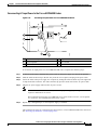
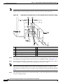
Figure 7-4
Removing the Strain-Relief Cover from a Cisco uBR7246VXR DC-Input Power Supply
1
2
8
3
9
4
5
6
Step 4
66408
7
1
Power switch
6
–V lead
2
Power receptacle
7
+V lead
3
Captive screw
8
Strain-relief cover
4
M5 grounding receptacles
9
M4 nuts and studs
5
M5 grounding lug
Using a 3/16-inch flat-blade screwdriver, loosen the screw below the +V lead receptacle and pull the lead
from the connector. Repeat this step for the –V lead only. See Figure 7-5.
Network Processing Engine and Network Services Engine Installation and Configuration
7-14
OL-4448-08
Chapter 7
NPE-G1 and NPE-G2 Installation and Configuration Information
Removing the Network Processing Engine
Figure 7-5
Disconnecting Power from a Cisco uBR7246VXR DC-Input Power Supply
2
1
9
3
4
7
5
Step 5
66406
8
6
1
Power switch
6
–V lead
2
Power receptacle
7
M4 studs
3
DC Power supply
8
+V lead
4
M5 grounding receptacles
9
Handle
5
M5 grounding lug
Using an 8-mm wrench or nut driver (or adjustable wrench), loosen and remove the two M5 nuts that
secure the two-hole grounding lug to the grounding receptacle, and pull the grounding lug and lead from
the receptacle.
Note
The color coding of the DC-input power supply leads depends on the color coding of the DC
power source at your site. Typically, green or green and yellow are used for ground. Make certain
that the lead color coding you choose for the DC-input power supply matches the lead color
coding used at the DC power source.
This completes the procedure for disconnecting DC-input power from a Cisco uBR7246VXR router. Go
to the following section, “Removing the NPE or NSE-1.”
Network Processing Engine and Network Services Engine Installation and Configuration
OL-4448-08
7-15
Chapter 7
NPE-G1 and NPE-G2 Installation and Configuration Information
Removing the Network Processing Engine
Removing the NPE or NSE-1
To remove the NPE or NSE-1 from a Cisco 7200 VXR or Cisco uBR7246VXR router complete the
following steps.
Note
The weight of installed power supplies in your Cisco 7200 VXR or Cisco uBR7246VXR router might
make it difficult to remove the network processing engine. If you have difficulty, first remove the power
supplies from the chassis, and then remove the network processing engine. See the “Removing and
Replacing an AC-Input or DC-Input Power Supply” section on page 10-14 for information on removing
and replacing an installed power supply.
Note
If you have difficulty installing a processing engine or I/O controller in the lowest slot of a Cisco 7200
VXR router that is rack-mounted, remove the port adapters, processing engine and I/O controller from
the chassis and reinstall them. Install the processing engine and I/O controller in the lowest slots first,
then populate the slots above them, in a bottom-to-top order.
Step 1
Power down the router and disconnect the input power cable. (See the “Powering Down the Router and
Disconnecting Input Power” section on page 7-8.)
Step 2
Attach an ESD-preventive wrist strap between you and an unfinished chassis surface.
Step 3
Using a number 2 Phillips or a 3/16-inch flat-blade screwdriver, loosen the two captive installation
screws on the faceplate of the network processing engine. (See Figure 7-6.)
If the router is not installed in a standard 19-inch, 4-post or telco-type rack, skip to Step 7. If the router
is installed in a rack, determine if any permanent rack fixtures, such as a power strip, are obstructing
access to the rear of the router. If a rack fixture is obstructing access to the router, proceed with Step 4.
Network Processing Engine and Network Services Engine Installation and Configuration
7-16
OL-4448-08
Chapter 7
NPE-G1 and NPE-G2 Installation and Configuration Information
Removing the Network Processing Engine
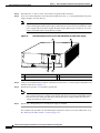
Cisco 7200 VXR Router NPE Captive Installation Screws and Handle
66605
Figure 7-6
NETWORK PROCESSING ENGINE-300
1
2
3
4
1
Captive installation screw
3
Network processing engine or network
services engine
2
Handle
4
AC-input power supply
Step 4
Using a 3/16-inch flat-blade screwdriver, loosen the screws that secure the router to the front mounting
strips of the rack.
Step 5
Position at least one person in front of the rack to support the front underside of the router.
Step 6
From the rear of the rack, carefully push the front of the router out of the rack until there is enough
clearance to remove the network processing engine.
Step 7
Grasp the network processing engine handle and carefully pull the network processing engine from its
chassis slot.
Caution
Step 8
Handle the network processing engine by the carrier edges and handle only; never touch the printed
circuit board components or connector pins.
Place the NPE on an antistatic surface with its printed circuit board components facing upward, or in a
static shielding bag. If you are returning the network processing engine to the factory, immediately place
it in a static shielding bag.
This completes the procedure for removing an installed NPE. For instructions on installing the NPE-G1
or NPE-G2, go to the “Installing the NPE-G1 or NPE-G2” section on page 7-18.
Network Processing Engine and Network Services Engine Installation and Configuration
OL-4448-08
7-17
Chapter 7
NPE-G1 and NPE-G2 Installation and Configuration Information
Installing the NPE-G1 or NPE-G2
Installing the NPE-G1 or NPE-G2
To install the NPE-G1 or NPE-G2 in the router, use the following procedures:
•
Basic Guidelines, page 7-18
•
Installing a CompactFlash Disk, page 7-19
•
Installing a USB Flash Memory Module or eToken—NPE-G2, page 7-19
•
Installing an SFP Module—NPE-G2, page 7-20
•
Installing a GBIC—NPE-G1, page 7-23
•
Replacing the DIMM on the NPE-G2, page 7-24
•
Upgrading the SDRAM SODIMMs on the NPE-G1 (Optional), page 7-26
•
Inserting the NPE-G1 or NPE-G2 into the Router, page 7-28
•
Attaching the Rear Cable-Management Brackets and Cables (Optional), page 7-29
•
Reconnecting Input Power and Powering Up the Router, page 7-35
Basic Guidelines
Note
If you have difficulty installing a processing engine or I/O controller in the lowest slot of a Cisco 7200
VXR router that is rack-mounted, remove the port adapters, processing engine and I/O controller from
the chassis and reinstall them. Install the processing engine and I/O controller in the lowest slots first,
then populate the slots above them, in a bottom-to-top order.
Please keep the following guidelines in mind when installing the NPE-G1 or NPE-G2:
Step 1
Ensure that the router is powered down and the input power cable is disconnected from the router and
the power source. See the “Powering Down the Router and Disconnecting Input Power” section on
page 7-8.
Step 2
Attach an ESD-preventive wrist strap between you and an unfinished chassis surface.
Step 3
Remove the NPE-G1 or NPE-G2 from its static shielding bag.
Step 4
Whenever you are touching the NPE-G1, use both hands, grasp the NPE-G1 or NPE-G2 by its metal
carrier edges, and orient it so that its printed circuit board components face upward.
Caution
Handle the NPE-G1 or NPE-G2 by the carrier edges and handle only; never touch the printed circuit
board components or connector pins.
Network Processing Engine and Network Services Engine Installation and Configuration
7-18
OL-4448-08
Chapter 7
NPE-G1 and NPE-G2 Installation and Configuration Information
Installing the NPE-G1 or NPE-G2
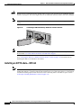
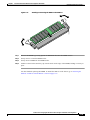
Installing a CompactFlash Disk
Use the following instructions to install the CompactFlash Disk.
Figure 7-7
Installing a CompactFlash Disk
1
2
ORK PR
OCESSING
ENGINE
ORK PR
OCESSING
CT FLA
SH
ENGINE
C O M PA
ORK PR
OCESSING
- G1
ENGINE
C O M PA
CT FLA
SH
- G1
CT FLA
SH
66776
C O M PA
- G1
3
1
Inserting the CompactFlash Disk
2
Pressing the ejector button to release the
CompactFlash Disk
3
Removing the CompactFlash Disk
Step 1
Turn the CompactFlash Disk so that the label is facing down.
Step 2
Slide the CompactFlash Disk into the CompactFlash Disk slot.
Step 3
To remove the CompactFlash Disk, push the ejector button, and gently pull the CompactFlash Disk from
its slot.
You are finished installing the CompactFlash Disk. For more information on using the CompactFlash
Disk, see Using the Flash Disk at the following URL:
http://www.cisco.com/en/US/products/hw/routers/ps341/prod_installation_guide09186a00802a6394.ht
ml
For instructions on installing an SFP module in the NPE-G2, go to the “Installing an SFP
Module—NPE-G2” section on page 7-20.
For instructions on installing a Gigabit Interface Converter (GBIC) in the NPE-G1, go to the “Installing
a GBIC—NPE-G1” section on page 7-23.
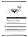
Installing a USB Flash Memory Module or eToken—NPE-G2
To connect a Cisco USB Flash memory module or the Aladdin USB eToken Pro key to the NPE-G2 USB
port, simply insert the module into the port as shown in Figure 7-8. The Flash memory module can be
inserted in only one way, and can be inserted or removed regardless of whether the router is powered up
or not.
Network Processing Engine and Network Services Engine Installation and Configuration
OL-4448-08
7-19
Chapter 7
NPE-G1 and NPE-G2 Installation and Configuration Information
Installing the NPE-G1 or NPE-G2
Caution
Do not remove a USB Flash memory module when a read or write operation to the USB Flash memory
module is in progress. The router might reload, or the USB Flash memory module card can be damaged.
Note
Only Cisco USB Flash memory modules and the Aladdin USB eToken Pro key are supported by Cisco
routers.
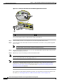
Figure 7-8
Connecting a USB Flash Memory Module to a Router USB Port
FE
LINK
U
S
B
AUX
Note
USB
138993
FE
FOR MA 0/2
NAG
USE ONEMENT
LY
For detailed information about the Cisco IOS commands that support USB Flash memory modules, see
the document Cisco IOS USB Flash Module and USB eToken Support.
Go to “Inserting the NPE-G1 or NPE-G2 into the Router” section on page 7-28 for instructions on
installing the NPE-G1 or NPE-G2 in the chassis.
Installing an SFP Module—NPE-G2
Note
The SFP module is a separately orderable part and ships installed in your NPE-G2. However, if you are
adding SFP modules, you must install the SFP module before you connect the cables to it. We strongly
recommend cleaning optical cable connectors before connecting them to the NPE-G2 ports. See the
“Fiber Optic Cleaning Information” section on page 7-65.
Network Processing Engine and Network Services Engine Installation and Configuration
7-20
OL-4448-08
Chapter 7
NPE-G1 and NPE-G2 Installation and Configuration Information
Installing the NPE-G1 or NPE-G2
Figure 7-9
Types of SFP Module Latches
2
3
80755
1
Note
1
Sliding latch
3
2
Swing and slide latch
Swing latch
The SFP module must be installed before you connect the cables to it.
•
The SPF module has three types of latches, which are also the removal mechanism. See Figure 7-9.
There is no correlation of the type of latch to the model (such as SX or LH) or technology type
(such as Gigabit Ethernet) of SFP modules. Always read the label on the SFP module to determine
the technology type, and model.
•
You can install and remove Gigabit Ethernet SFP modules with power on to the system.
•
We strongly recommend that you clean optical fiber cable connectors before attaching them to SFP
modules. See the “Fiber Optic Cleaning Information” section on page 7-65.
•
Disconnect all cables before removing or installing a Gigabit Ethernet SFP module. We strongly
recommend that you do not install or remove the SFP with optical fiber cables attached to it.
•
SFP modules are keyed to prevent incorrect insertion.
Warning
Invisible laser radiation may be emitted from disconnected fibers or connectors. Do not stare into
beams or view directly with optical instruments. Statement 1051
Warning
Class 1 laser product. Statement 1008
Warning
Class 1 LED product. Statement 1027
Warning
During this procedure, wear grounding wrist straps to avoid ESD damage to the card. Do not directly
touch the backplane with your hand or any metal tool, or you could shock yourself. Statement 94
Network Processing Engine and Network Services Engine Installation and Configuration
OL-4448-08
7-21
Chapter 7
NPE-G1 and NPE-G2 Installation and Configuration Information
Installing the NPE-G1 or NPE-G2
Figure 7-10 Inserting an SFP Module into the NPE-G2 Gigabit Ethernet Port 0/1
LINK
ACTV
1
EN
GIGABI
T ETHE
RNET 0
LINK
ACTV
/1
GIGABI
T ETHE
RNET 0
LINK
ACTV
TX
RX
RJ45
/2
EN
EN
149065
RJ45
2
1
SFP port 0/1
2
SFP module
Use the following procedure to install an SFP module in the NPE-G2:
Step 1
Attach an ESD-preventive wrist strap between you and an unpainted chassis surface.
Step 2
Locate the label on the SFP module and turn the SFP module so the label is on top and the alignment
groove is down.
Note
The SFP module is keyed so that it cannot be inserted incorrectly.
Step 3
Insert the SFP module into SFP port 0/1, 0/2, or 0/3. The SFP module snaps into place when you have
completely and properly inserted it.
Step 4
Repeat Step 2 if you are inserting a second or third SFP module.
Note
Do not remove the plug from the SFP module optical bores until you are ready to install the network
interface optical fiber cable. Save the plug for future use.
Note
We strongly recommend cleaning all optical fiber connections before connecting optical cables to
equipment. For information about cleaning optical connectors, see the Inspection and Cleaning
Procedures for Fiber-Optic Connections document and the Compressed Air Cleaning Issues for
Fiber-Optic Connections document.
This completes the SFP module installation procedure. For information on inserting the NPE-G2 into
the chassis, see “Inserting the NPE-G1 or NPE-G2 into the Router” section on page 7-28.
Network Processing Engine and Network Services Engine Installation and Configuration
7-22
OL-4448-08
Chapter 7
NPE-G1 and NPE-G2 Installation and Configuration Information
Installing the NPE-G1 or NPE-G2
Installing a GBIC—NPE-G1
Use the instructions in this section to install a GBIC in the NPE-G1.
Figure 7-11
Installing a GBIC in the NPE-G1
3
ETHER
NET 0
/1
4
GIGAB
IT ETH
ER
LINK
5
RX
GBIC
NET 0
/2
TX
RJ45
EN
RX
GBIC
66774
2
1
Step 1
1
GBIC
4
GBIC port 0/2
2
Alignment groove
5
Plug
3
GBIC port 0/1
Turn the GBIC so the label side is up and the alignment groove is down.
Note
Step 2
The GBIC is keyed so that it cannot be inserted incorrectly.
Insert the GBIC into GBIC port 0/1, 0/2, or 0/3. Repeat this step if you are installing more than one
GBIC.
Note
Do not remove the GBIC plugs until you are ready to install the cables.
You are finished installing the GBICs. For more information on cabling or specifications, see the
“Gigabit Ethernet GBIC Connection Equipment” section on page 5-13.
Note
We strongly recommend cleaning all optical fiber connections before connecting optical cables to
equipment. For information about cleaning optical connectors, see the Inspection and Cleaning
Procedures for Fiber-Optic Connections document and the Compressed Air Cleaning Issues for
Fiber-Optic Connections document.
Go to “Inserting the NPE-G1 or NPE-G2 into the Router” section on page 7-28 for instructions on
installing the NPE-G1 or NPE-G2 in the chassis.
Network Processing Engine and Network Services Engine Installation and Configuration
OL-4448-08
7-23
Chapter 7
NPE-G1 and NPE-G2 Installation and Configuration Information
Installing the NPE-G1 or NPE-G2
Replacing the DIMM on the NPE-G2
If you are replacing the DIMM on the NPE-G2, use the following instructions.
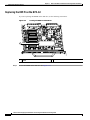
Figure 7-12
Locating the DIMM on the NPE-G2
149472
1
1
Step 1
DIMM
Locate the DIMM on the NPE-G2. See Figure 7-12.
Network Processing Engine and Network Services Engine Installation and Configuration
7-24
OL-4448-08
Chapter 7
NPE-G1 and NPE-G2 Installation and Configuration Information
Installing the NPE-G1 or NPE-G2
Installing or Removing the DIMM on the NPE-G2
149068
Figure 7-13
Step 1
Remove the DIMM by pressing against the DIMM latches until the DIMM releases.
Step 2
Gently remove it from the DIMM socket.
Step 3
Gently insert a DIMM into the DIMM socket.
Step 4
Push the release latches until they slip into the notch on the edge of the DIMM, holding it securely in
place.
You have finished replacing the DIMM. To install the NPE-G2 in the chassis, go to “Inserting the
NPE-G1 or NPE-G2 into the Router” section on page 7-28.
Network Processing Engine and Network Services Engine Installation and Configuration
OL-4448-08
7-25
Chapter 7
NPE-G1 and NPE-G2 Installation and Configuration Information
Installing the NPE-G1 or NPE-G2
Upgrading the SDRAM SODIMMs on the NPE-G1 (Optional)
If you have purchased an SDRAM memory upgrade for the NPE-G1, replace the SDRAM SODIMMs
on the NPE-G1 using the following instructions.
Removing a SODIMM
Figure 7-14
Locating the SODIMMs on the NPE-G1
2
1
GIGABIT ETHERNET 0/1
GIGABIT ETHERNET 0/1
LINK
EN
GBIC
TX
EN
RJ45
NETWORK PROCESSING ENGINE - G1
GIGABIT ETHERNET 0/1
LINK
RX
LINK
RX
GBIC
TX
EN
RJ45
SLOT
ACTIVE
CPU
RESET
RX
GBIC
TX
C O M PA C T F L A S H
POWER
ON
CONSOLE
AUX
66948
RJ45
1
Step 1
Note
SODIMM 2
2
SODIMM 1
Locate the SODIMMs on the NPE-G1.
Both SODIMMs must be of the same size and type, and both SODIMM sockets must be populated.
Network Processing Engine and Network Services Engine Installation and Configuration
7-26
OL-4448-08
Chapter 7
NPE-G1 and NPE-G2 Installation and Configuration Information
Installing the NPE-G1 or NPE-G2
Figure 7-15
Removing or Installing an SDRAM SODIMM
66437
1
1
Step 2
SODIMM
Remove the SODIMM you wish to replace by pulling outward on the SODIMM spring latches with your
thumbs.
The SODIMM springs up to allow you to easily pull it from the socket.
Step 3
Remove the SODIMM from the socket. Avoid touching the SODIMM as much as possible, particularly
the traces, the metal fingers on the connector side of the SODIMM.
Step 4
Place the SODIMM in an antistatic shielding bag, if you are keeping it.
Installing a SDRAM SODIMM
Caution
SODIMMs are sensitive components that are susceptible to ESD damage. Handle SODIMMs by the
edges only; avoid touching the memory modules, pins, or traces (the metal fingers along the connector
edge of the SODIMM).
Step 1
Remove a new SODIMM from the antistatic container.
Step 2
Hold the SODIMM component-side-up, with the connector edge (the metal fingers) away from you.
Step 3
Align the new SODIMM notch with the connector and insert the SODIMM into the socket.
Network Processing Engine and Network Services Engine Installation and Configuration
OL-4448-08
7-27
Chapter 7
NPE-G1 and NPE-G2 Installation and Configuration Information
Installing the NPE-G1 or NPE-G2
Caution
When inserting the SODIMM, use firm but not excessive pressure. If you damage a socket, you will have
to return the NPE-G1 to the factory for repair.
Step 4
Gently press on the SODIMM until the SODIMM spring latches snap into place.
Step 5
If the SODIMM appears misaligned, carefully remove it and reseat it in the socket. Push the SODIMM
gently back into the socket until the spring latches snap into place.
You have finished replacing the SDRAM SODIMM. To install the NPE-G1 in the chassis, go to
“Inserting the NPE-G1 or NPE-G2 into the Router” section on page 7-28.
Inserting the NPE-G1 or NPE-G2 into the Router
Note
If you have difficulty installing a processing engine or I/O controller in the lowest slot of a Cisco 7200
VXR router that is rack-mounted, remove the port adapters, processing engine and I/O controller from
the chassis and reinstall them. Install the processing engine and I/O controller in the lowest slots first,
then populate the slots above them, in a bottom-to-top order.
To insert the NPE-G1 or NPE-G2 into the router, follow the instructions in this section:
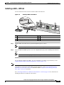
Step 1
Align the left and right edges of the NPE-G1 or NPE-G2 with the chassis slot guides. Figure 7-16 shows
an NPE-G1 being installed into a Cisco 7200 VXR router; inserting an NPE-G2 is similar. Inserting a
Cisco uBR7200-NPE-G1 in a Cisco uBR7246VXR router is similar.
Aligning the NPE-G1 Between the Slot Guides on a Cisco 7200 VXR Router
66773
Figure 7-16
1
GIGABIT ETHERNET 0/1
GIGABIT ETHERNET 0/1
LINK
GIGABIT ETHERNET 0/1
LINK
NETWORK PROCESSING ENGINE - G1
LINK
CPU
RESET
RJ45
EN
RX
GBIC
TX
RJ45
EN
RX
GBIC
TX
RJ45
SLOT
ACTIVE
EN
RX
GBIC
TX
C O M PA C T F L A S H
POWER
ON
CONSOLE
AUX
3
4
2
1
Slot guides
3
Printed circuit board
2
NPE-G1
4
Metal carrier
Network Processing Engine and Network Services Engine Installation and Configuration
7-28
OL-4448-08
Chapter 7
NPE-G1 and NPE-G2 Installation and Configuration Information
Installing the NPE-G1 or NPE-G2
Step 2
Gently slide the NPE-G1 or NPE-G2 all the way into its chassis slot until you feel the connectors seat
with the router midplane.
Step 3
Seat the NPE-G1 or NPE-G2 in the router midplane by tightening its captive installation screws with a
number 2 Phillips or a 3/16-inch flat-blade screwdriver.
Note
The NPE-G1 or NPE-G2 is not fully seated in the router midplane until you tighten its captive
installation screws.
Step 4
If you removed power supplies from the router, replace the power supplies. (See the “Removing and
Replacing an AC-Input or DC-Input Power Supply” section on page 10-14 when replacing a power
supply in a Cisco 7200 VXR router.)
Step 5
If you slid the front of the router out of the rack, slowly guide the router back into the rack.
Step 6
Use a 3/16-inch flat-blade screwdriver to tighten the screws that secure the router to the front mounting
strips of the rack.
This completes the procedure for installing the NPE-G1 or NPE-G2 in a Cisco 7200 VXR router.
Attaching the Rear Cable-Management Brackets and Cables (Optional)
You may choose to use one of two types of cable-management brackets. One type is the same as is used
on the front of the router for managing port adapter and I/O controller cables. The NPE-G1or NPE-G2
-specific bracket is used only on the NPE-G1 or NPE-G2, and provides more support for optical fiber
cables.
Depending on whether the router is front-mounted or rear-mounted in the rack, install the
cable-management brackets to the router. Go to one of these sections for instructions on rear-mounting
the cable-management brackets and attaching the cables:
•
Installing the NPE-G1 or NPE-G2 Cable-Management Brackets, page 7-29—This procedure applies
to both the Cisco 7200 VXR and Cisco uBR7246VXR routers.
•
Installing the Rear Cable-Management Brackets on a Front-Mounted Router (Optional), page
7-31—This procedure applies to only the Cisco 7200 VXR router.
•
Installing the Rear Cable-Management Brackets on a Rear-Mounted Router (Optional), page
7-32—This procedure applies to only the Cisco 7200 VXR router.
•
Installing the Default Cable-Management Bracket on a Cisco uBR7246VXR Router (Optional),
page 7-34—This procedure applies to only the Cisco 7246VXR universal broadband router.
Installing the NPE-G1 or NPE-G2 Cable-Management Brackets
If you are using the NPE-G1 or NPE-G2 and installing the cable-management bracket (Cisco Product
Number MAS-7200-CBLMGMT), use the following instructions. Use Figure 7-17 when installing the
bracket on the NPE-G1 or NPE-G2 on the Cisco 7200 VXR router. Use Figure 7-18 when installing the
bracket on the Cisco uBR7200-NPE-G1 on the Cisco uBR7246VXR router.
Network Processing Engine and Network Services Engine Installation and Configuration
OL-4448-08
7-29
Chapter 7
NPE-G1 and NPE-G2 Installation and Configuration Information
Installing the NPE-G1 or NPE-G2
Note
The captive installation screws on the NPE-G1 or NPE-G2 must be fastened to allow the
cable-management bracket to provide proper cable support and strain relief. Always ensure that the
captive installation screws are properly tightened.
Note
Do not use the cable-management bracket as a handle for inserting and removing the NPE-G1 or
NPE-G2 in the chassis. You must always first unfasten the NPE-G1 or NPE-G2 captive installation
screws and remove the cable-management bracket before removing or inserting the NPE-G1 or NPE-G2
in the chassis.
Figure 7-17
Installing the NPE-G1 or NPE-G2 Cable-Management Bracket
80680
.
GIGABIT ETHERNET 0/1
GIGABIT ETHERNET 0/1
LINK
GIGABIT ETHERNET 0/1
LINK
NETWORKNETWORK
PROCESSING
PROCESSING
ENGINE - ENGINE-300
G1
LINK
CPU
RESET
RJ45
EN
RX
GBIC
TX
RJ45
EN
RX
GBIC
TX
RJ45
SLOT
ACTIVE
EN
RX
GBIC
TX
C O M PA C T F L A S H
POWER
OK
1
1
CONSOLE
AUX
2
Captive installation screw
2
Captive installation screw
Network Processing Engine and Network Services Engine Installation and Configuration
7-30
OL-4448-08
Chapter 7
NPE-G1 and NPE-G2 Installation and Configuration Information
Installing the NPE-G1 or NPE-G2
Figure 7-18
Installing the Cisco uBR7200-NPE-G1 Cable-Management Bracket
.
EN
EN
RX
GBIC
TX
RJ45
NETWORK PROCESSING ENGINE - G1
LINK
LINK
LINK
RJ45
GIGABIT ETHERNET 0/1
GIGABIT ETHERNET 0/1
GIGABIT ETHERNET 0/1
1
EN
RX
GBIC
TX
RJ45
SLOT
ACTIVE
CPU
RESET
RX
GBIC
TX
C O M PA C T F L A S H
POWER
ON
CONSOLE
AUX
82702
2
1
Captive installation screw
2
Captive installation screw
Step 1
Loosen the left and right captive installation screws on the NPE-G1 or NPE-G2.
Step 2
Hold the cable-management bracket so that it is positioned above the NPE-G1 or NPE-G2 captive
installation screws as shown in Figure 7-17 and Figure 7-18. The bracket is properly positioned when
the horizontally-faced notch is at the left, the vertically-faced notch is at the right, and the bracket’s outer
edge is flush with the edge on the NPE-G1 or NPE-G2. If you reverse the bracket, so that it is not flush
with the NPE-G1 or NPE-G2, you will not be able to access the GBIC or SFP connectors on the NPE-G1
or NPE-G2 front panel.
Step 3
Slide the left end of the bracket between the captive installation screw and the front panel of the NPE-G1
or NPE-G2.
Step 4
Rotate the cable-management bracket down, until its other notch slides behind the right captive
installation screw. Make sure the bracket’s outer edge is flush with the edge of the NPE-G1 or NPE-G2
and does not obstruct the GBIC or SFP ports.
Step 5
Tighten both captive installation screws.
Step 6
Install the cables, and fasten them to the bracket with the velcro straps provided.
Installing the Rear Cable-Management Brackets on a Front-Mounted Router (Optional)
Use the instructions in this section to attach the cable-management brackets to a front-mounted
Cisco 7200 VXR router.
Network Processing Engine and Network Services Engine Installation and Configuration
OL-4448-08
7-31
Chapter 7
NPE-G1 and NPE-G2 Installation and Configuration Information
Installing the NPE-G1 or NPE-G2
Installing the Rear Cable-Management Brackets with an NPE-G1—Router
Front-Mounted
H6423
Figure 7-19
1
1
GIGABIT ETHERNET 0/1
GIGABIT ETHERNET 0/1
LINK
GIGABIT ETHERNET 0/1
LINK
NETWORK PROCESSING ENGINE - G1
LINK
CPU
RESET
EN
RX
GBIC
TX
RJ45
EN
RX
GBIC
TX
RJ45
SLOT
ACTIVE
EN
RX
GBIC
TX
C O M PA C T F L A S H
POWER
OK
CONSOLE
AUX
66749
RJ45
1
Screws
Step 1
If the back of the router protrudes from the rack, place the cable-management brackets against the router
as shown in Figure 7-19.
Step 2
Insert two screws into each bracket, and tighten them to the router.
Step 3
Insert the GBIC, SFP, or RJ-45 cables into the interface ports on the NPE-G1 or NPE-G2.
Step 4
Place the cables through the cable-management brackets.
You have finished installing the cable-management brackets. Go to the “Reconnecting Input Power and
Powering Up the Router” section on page 7-35.
Installing the Rear Cable-Management Brackets on a Rear-Mounted Router (Optional)
Use the instructions in this section to attach the cable-management brackets if you have a rear-mounted
Cisco 7200 VXR router.
Network Processing Engine and Network Services Engine Installation and Configuration
7-32
OL-4448-08
Chapter 7
NPE-G1 and NPE-G2 Installation and Configuration Information
Installing the NPE-G1 or NPE-G2
Installing the Rear Cable-Management Brackets with the NPE-G1 or NPE-G2—Router
Rear-Mounted
66750
Figure 7-20
EN
1
GIGABIT ETHERNET 0/1
GIGABIT ETHERNET 0/1
LINK
GIGABIT ETHERNET 0/1
LINK
NETWORK PROCESSING ENGINE - G1
LINK
CPU
RESET
RJ45
1
EN
RX
GBIC
TX
RJ45
EN
RX
GBIC
TX
RJ45
1
SLOT
ACTIVE
EN
RX
GBIC
TX
C O M PA C T F L A S H
POWER
ON
CONSOLE
AUX
Screws
Step 1
Align the cable-management brackets with the rack-mount brackets as shown in Figure 7-20.
Step 2
Insert and tighten two screws for each bracket. The screws come with the cable-management brackets.
Figure 7-21
Attaching Console and Auxiliary Port Cables
1
NETWOR
CPU
RESET
K PROC
ESSIN
G ENGIN
E
2
- G1
SLOT
ACTIVE
CT FLA
SH
POWER
ON
CO NS O
LE
AU X
66777
C O M PA
3
4
5
1
Console port
4
Cable to console terminal or DTE
2
Auxiliary port
5
Cable to modem or DCE
3
RJ-45 connectors
Step 3
Insert the console and auxiliary RJ-45 cables into the interface ports on the NPE-G1 or NPE-G2.
Step 4
Place the cables through the cable-management brackets.
Network Processing Engine and Network Services Engine Installation and Configuration
OL-4448-08
7-33
Chapter 7
NPE-G1 and NPE-G2 Installation and Configuration Information
Installing the NPE-G1 or NPE-G2
You have finished installing the cable-management brackets. Go to the “Reconnecting Input Power and
Powering Up the Router” section on page 7-35.
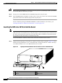
Installing the Default Cable-Management Bracket on a Cisco uBR7246VXR Router (Optional)
If you are not using the NPE-G1 cable-management bracket, you can alternatively use two
cable-management bracket configurations for the Cisco uBR7246VXR router. In the first configuration,
for a 4-post rack, the rack-mount brackets are installed at the rear of the chassis and the
cable-management bracket is installed at the right front of the chassis. (See Figure 7-22 on page 7-34.)
You must install both sets of brackets before you install the chassis in the rack.
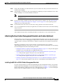
In the second configuration, for a telco-type rack, the rack-mount brackets are installed at the middle of
the chassis and the cable-management bracket is installed at the right front of the chassis. (See
Figure 7-23 on page 7-35.) You must install both sets of brackets before you install the chassis in the
rack.
Note
The cable-management bracket must be installed on the right side of the chassis when viewed from the
front.
Installing the Chassis in a 4-Post Rack with an Installed Cable-Management Bracket
93812
Figure 7-22
1
1
Rack-mount bracket
2
2
Cable-management bracket
Network Processing Engine and Network Services Engine Installation and Configuration
7-34
OL-4448-08
Chapter 7
NPE-G1 and NPE-G2 Installation and Configuration Information
Installing the NPE-G1 or NPE-G2
Installing the Chassis in a Telco-Type Rack with an Installed Cable-Management
Bracket
1
1
2
Rack-mount bracket
93812
Figure 7-23
2
Cable-management bracket
Reconnecting Input Power and Powering Up the Router
The following procedures explain how to reconnect input power to a Cisco 7200 VXR or
Cisco uBR7246VXR router, power up the router, and verify a successful system boot.
Warning
Read the installation instructions before you connect the system to its power source. Statement 10
Reconnecting AC-Input Power to the Cisco 7200 VXR Router
To reconnect AC-input power to a Cisco 7200 VXR router, complete the following steps:
Step 1
At the rear of the router, check that the power switch on the power supply is in the off (O) position.
Step 2
Slide the cable-retention clip up away from the AC receptacle, and plug in the power cable.
Step 3
Secure the cable in the power supply AC receptacle by sliding the cable-retention clip down until it snaps
around the connector. The cable-retention clip provides strain relief for the AC power cable.
Network Processing Engine and Network Services Engine Installation and Configuration
OL-4448-08
7-35
Chapter 7
NPE-G1 and NPE-G2 Installation and Configuration Information
Installing the NPE-G1 or NPE-G2
Figure 7-24
Connecting AC-Input Power to a Cisco 7200 VXR Router
84398
1
3
2
Step 4
4
5
1
Power switch
4
Cable-retention clip
2
AC power cable
5
Hole for nylon cable tie
3
POWER OK LED
Plug the AC power supply cable into the AC power source.
Note
For Cisco 7200 VXR routers, each AC-input power supply operating at 120 VAC requires a
minimum of 5A service.
We recommend powering the Cisco 7200 VXR routers from a 120 VAC, 15A receptacle U.S.
(240 VAC, 10A international) at the power source.
Step 5
Repeat Step 1 through Step 4 if a second power supply is installed.
This completes the steps for reconnecting AC-input power to a Cisco 7200 VXR router. Proceed to the
“Powering Up the Router” section on page 7-43.
Network Processing Engine and Network Services Engine Installation and Configuration
7-36
OL-4448-08
Chapter 7
NPE-G1 and NPE-G2 Installation and Configuration Information
Installing the NPE-G1 or NPE-G2
Reconnecting AC-Input Power to the Cisco uBR7246VXR Router
Figure 7-25
Connecting AC-Input Power to a Cisco uBR7246VXR Router
1
6
5
2
3
66422
4
1
Cable-retention clip
4
AC power cable
2
Power receptacle
5
Power switch
3
Captive installation screw
6
Handle
To reconnect AC-input power to a Cisco uBR7246VXR router, complete the following steps:
Step 1
At the rear of the router, check that the power switch on the power supply is in the off (O) position.
Step 2
Slide the cable-retention clip to the left away from the AC receptacle, and plug in the power cable.
Step 3
Secure the cable in the power supply AC receptacle by sliding the cable-retention clip to the right until
it snaps around the connector. The cable-retention clip provides strain relief for the AC power cable.
Step 4
Plug the AC power supply cable into the AC power source.
Note
For the Cisco uBR7200 series routers, each AC-input power supply operating at 120 VAC
requires a minimum of 7A service.
We recommend powering the Cisco uBR7200 series routers from a 120 VAC, 15A receptacle
U.S. (240 VAC, 10A international) at the power source.
Step 5
Repeat Step 1 through Step 4 if a second power supply is installed.
This completes the steps for reconnecting AC-input power to a Cisco uBR7246VXR router. Proceed to
the “Powering Up the Router” section on page 7-43.
Network Processing Engine and Network Services Engine Installation and Configuration
OL-4448-08
7-37
Chapter 7
NPE-G1 and NPE-G2 Installation and Configuration Information
Installing the NPE-G1 or NPE-G2
Reconnecting DC-Input Power to the Cisco 7200 VXR Router
To reconnect DC-input power to a Cisco 7200 VXR router, complete the following steps.
Note
The color coding of the DC-input power supply leads depends on the color coding of the DC power
source at your site. Typically, green or green and yellow are used for ground. Make certain that the lead
color coding you choose for the DC-input power supply matches the lead color coding used at the DC
power source.
Warning
Before completing any of the following steps, and to prevent short-circuit or shock hazards, ensure
that power is removed from the DC circuit. To ensure that all power is OFF, locate the circuit breaker
on the panel board that services the DC circuit, switch the circuit breaker to the OFF position, and
tape the switch handle of the circuit breaker in the OFF position. Statement 322
Warning
When installing the unit, the ground connection must always be made first and disconnected last.
Statement 42
Step 1
At the rear of the router, check that the power switch on the power supply is in the off (O) position.
Step 2
Ensure that no current is running through the –V and +V leads. To ensure that all power is off, locate the
circuit breaker on the panel board that services the DC circuit, switch the circuit breaker to the off
position, and tape the switch handle of the circuit breaker in the Off position.
Figure 7-26
Connecting DC-Input Power to a Cisco 7200 VXR Router
66432
1
2
3
4
Step 3
1
Power switch
3
Cable tie
2
Ground lead service loop
4
DC power leads
If necessary, use a wire stripper to strip approximately 0.55 inch (14 mm) from the –V, +V, and ground
leads. (See Figure 7-27.)
Network Processing Engine and Network Services Engine Installation and Configuration
7-38
OL-4448-08
Chapter 7
NPE-G1 and NPE-G2 Installation and Configuration Information
Installing the NPE-G1 or NPE-G2
Figure 7-27
Stripping the DC-Input Lines
57019
1
1
0.55 in. (14 mm)
Step 4
For the Cisco 7200 VXR routers, insert the stripped end of the ground lead all the way into the ground
lead receptacle on the DC-input power supply and tighten the receptacle screw using a 3/16-inch
flat-blade screwdriver.
Step 5
Insert the stripped end of the +V lead all the way into the +V lead receptacle and tighten the receptacle
screw using the same 3/16-inch flat-blade screwdriver. Repeat this step for the –V lead.
Note
Make sure that the entire stripped end of each lead is inserted all the way into its receptacle. If any
exposed wire at the stripped end of a lead is visible after inserting the lead into its receptacle, remove
the lead from the receptacle, use the wire stripper to cut the stripped end of the lead, and repeat through
Step 5.
Step 6
After tightening the receptacle screws for the ground, +V, and –V DC-input leads, secure the leads to the
power supply faceplate.
Use the cable tie you saved earlier in this procedure to secure the three leads.
Note
Step 7
When securing the ground, +V, and –V DC-input leads to the power supply faceplate, leave a
small service loop in the ground lead to ensure that it is the last lead to disconnect from the power
supply if a great deal of strain is placed on all three leads. (See Figure 7-26.)
Restore current to the –V and +V leads.
Note
For the Cisco 7200 VXR routers:
– Each DC-input power supply operating at 24 VDC requires a minimum of 19A service.
– Each DC-input power supply operating at 48 VDC requires a minimum of 13A service.
– Each DC-input power supply operating at 60 VDC requires a minimum of 8A service.
This product relies on the building’s installation for short-circuit (overcurrent) protection.
Ensure that a listed and certified fuse or circuit breaker, 35A minimum 60 VDC, is used on all
current-carrying conductors. Site wiring and circuit breakers need to be sized to accommodate
the maximum values for safety reasons.
Step 8
Repeat Step 1 through Step 7 if a second power supply is installed.
Network Processing Engine and Network Services Engine Installation and Configuration
OL-4448-08
7-39
Chapter 7
NPE-G1 and NPE-G2 Installation and Configuration Information
Installing the NPE-G1 or NPE-G2
This completes the steps for reconnecting DC-input power to a Cisco 7200 VXR router. Proceed to the
section, “Powering Up the Router” section on page 7-43.
Reconnecting DC-Input Power to a Cisco uBR7246VXR Router
To reconnect DC-input power to a Cisco uBR7246VXR router, complete the following steps.
Note
The color coding of the DC-input power supply leads depends on the color coding of the DC power
source at your site. Typically, green or green and yellow are used for ground. Make certain that the lead
color coding you choose for the DC-input power supply matches the lead color coding used at the DC
power source.
Warning
Before completing any of the following procedures, and to prevent short-circuit or shock hazards,
ensure that power is removed from the DC circuit. To ensure that all power is OFF, locate the circuit
breaker on the panel board that services the DC circuit, switch the circuit breaker to the OFF position,
and tape the switch handle of the circuit breaker in the OFF position. Statement 322
Warning
When installing the unit, the ground connection must always be made first and disconnected last.
Statement 42
Network Processing Engine and Network Services Engine Installation and Configuration
7-40
OL-4448-08
Chapter 7
NPE-G1 and NPE-G2 Installation and Configuration Information
Installing the NPE-G1 or NPE-G2
Figure 7-28
Connecting DC-Input Power to a Cisco uBR7246VXR Router
1
2
9
3
4
7
66407
8
5
6
1
Power switch
6
–V lead
2
Power receptacle
7
M4 studs
3
Captive installation screw
8
+V lead
4
M5 grounding receptacles
9
Handle
5
M5 grounding lug
Step 1
At the rear of the router, check that the power switch on the power supply is in the off (O) position.
Step 2
Ensure that no current is running through the –V and +V leads. To ensure that all power is off, locate the
circuit breaker on the panel board that services the DC circuit, switch the circuit breaker to the off
position, and tape the switch handle of the circuit breaker in the off position.
Figure 7-29
Stripping the DC-Input Lines
57019
1
1
Step 3
0.55 in. (14 mm)
If necessary, use a wire stripper to strip approximately 0.55 inch (14 mm) from the –V, +V, and ground
leads.
Network Processing Engine and Network Services Engine Installation and Configuration
OL-4448-08
7-41
Chapter 7
NPE-G1 and NPE-G2 Installation and Configuration Information
Installing the NPE-G1 or NPE-G2
Note
The ground lead for the Cisco uBR7200 series DC-input power supply consists of a two-hole grounding
lug that connects to an M5 grounding receptacle; you do not need to strip this ground lead.
Figure 7-30
Replacing the Strain-Relief Cover on a Cisco uBR7200 Series DC-Input Power Supply
1
2
3
8
4
66409
5
7
6
1
Power switch
6
–V lead
2
Power receptacle
7
+V lead
3
Captive installation screw
8
Strain-relief cover
4
M5 grounding receptacles
9
M4 nuts
5
M5 grounding lug
9
Step 4
Connect the two-hole grounding lug on the grounding lead to the M5 grounding receptacles with the M5
nuts. Tighten the nuts using an 8-mm wrench or nut driver (or adjustable wrench). (See Figure 7-30.)
Step 5
Insert the stripped end of the +V lead all the way into the +V lead receptacle and tighten the receptacle
screw using the 3/16-inch flat-blade screwdriver. Repeat this step for the –V lead.
Note
Make sure that the entire stripped end of each lead is inserted all the way into its receptacle. If any
exposed wire at the stripped end of a lead is visible after inserting the lead into its receptacle, remove
the lead from the receptacle, use the wire stripper to cut the stripped end of the lead, and repeat through
Step 5.
Step 6
After tightening the receptacle screw or nuts for the ground, +V, and –V DC-input leads, secure the leads
to the power supply faceplate.
Network Processing Engine and Network Services Engine Installation and Configuration
7-42
OL-4448-08
Chapter 7
NPE-G1 and NPE-G2 Installation and Configuration Information
Installing the NPE-G1 or NPE-G2
Step 7
Run the +V and –V leads between the two strain-relief studs on the power supply faceplate.
Note
A service loop is not required in the lead attached to the grounding lug because this lead is
separate from the +V and –V leads and is secured by two M5 nuts to the M5 receptacles.
Step 8
Replace the strain-relief cover over the +V and –V leads and secure the cover to the strain-relief studs
with the two M4 nuts using the 7-mm wrench or nut driver (or adjustable wrench).
Step 9
Restore current to the –V and +V leads.
Note
For the Cisco uBR7200 series routers, each DC-input power supply rating is 14A, 700 volt
ampere (VA).
This product relies on the building’s installation for short-circuit (overcurrent) protection.
Ensure that a listed and certified fuse or circuit breaker, 35A minimum 60 VDC, is used on all
current-carrying conductors. Site wiring and circuit breakers need to be sized to accommodate
the maximum values for safety reasons.
Step 10
Repeat Step 1 through Step 9 if a second power supply is installed.
This completes the steps for reconnecting DC-input power to a Cisco uBR7246 router. Proceed to the
following section, “Powering Up the Router.”
Powering Up the Router
To power up a Cisco 7200 VXR or Cisco uBR7246VXR router that has an installed power supply,
complete the following steps:
Step 1
Check for the following:
– Each port adapter is inserted in its slot, and its respective port adapter lever is in the locked
position.
– The network processing engine and the I/O controller or I/O controller blank panel are inserted
in their respective slots, and the captive installation screws are tightened.
– All network interface cables are connected to the port adapters or I/O controller or NPE-G1 or
NPE-G2 interfaces.
– Each cable interface line card is inserted in its slot, and its respective captive installation screws
are tightened (Cisco uBR7246VXR only).
– (Optional) A CompactFlash Disk is installed in the CompactFlash Disk slot in the NPE-G1or
NPE-G2. If you also have an I/O controller installed, you can optionally install a PC Card or
Flash Disk in one of the controller’s PC Card slots.
Note
A Flash Disk can be installed in either slot 0 or slot 1 of the I/O controller. A
CompactFlash Disk can be installed only in the CompactFlash Disk slot in the NPE-G1
or NPE-G2.
– (Optional) A USB Flash memory module or eToken is inserted into a USB port on the NPE-G2.
Network Processing Engine and Network Services Engine Installation and Configuration
OL-4448-08
7-43
Chapter 7
NPE-G1 and NPE-G2 Installation and Configuration Information
Installing the NPE-G1 or NPE-G2
– Each AC-input power cable is connected and secured with the cable-retention clip (AC-input
power supplies only).
– For a Cisco 7200 VXR router, each DC lead is connected and secured to the power supply
faceplate with a cable tie.
– For a Cisco uBR7246VXR router, each DC lead is connected with M4 nuts for the grounding
receptacle and the strain-relief cover over the +V and –V leads (DC-input power supplies only).
– Each DC lead is connected and secured to the power source (DC-input power supplies only).
– Ensure that the tape (that you applied earlier) is removed from the circuit breaker switch handle,
and power is restored by moving the circuit breaker handle to the on (|) position (DC-input
power supplies only).
– The console terminal is turned on.
Caution
Step 2
Note
When the power switch on a Cisco uBR7200 series power supply is turned to the off (O) position, the
power supply enters a reset cycle for 90 seconds. Wait at least 90 seconds before turning the power
switch back to the on (|) position. If you do not wait the full 90 seconds, the power supply does not
restart.
At the rear of the router, place the power switch on the power supply in the on (|) position. Repeat this
step if a second power supply is installed in the router. The green OK LED on the power supply turns on.
When powering on the router, wait a minimum of 30 seconds before powering it off again.
Step 3
Listen for the fans; you should immediately hear them operating.
Step 4
During the boot process, observe the system LEDs. The LEDs on most of the port adapters go on and
off in an irregular sequence. Some may go on, go off, and go on again for a short time. On the NPE-G1
or NPE-G2 and the I/O controller, the POWER OK LED goes on immediately.
Step 5
Observe the initialization process. When the system boot is complete (a few seconds), the NPE-G1 or
NPE-G2 begins to initialize the port adapters and the I/O controller. During this initialization, the LEDs
on each port adapter behave differently (most flash on and off). The enabled LED on each port adapter
and Cisco uBR7200 series cable interface line card goes on when initialization is completed, and the
console screen displays a script and system banner similar to the following:
Cisco Internetwork Operating System Software
IOS (tm) 7200 Software (C7200-J-M), 11.3(2)T
Copyright (c) 1986-1998 by cisco Systems, Inc.
Compiled Sun 22-Feb-98 06:00 by Biff
This completes the procedures for connecting input power and powering up the router. This also
completes the procedure for installing the NPE-G1 or NPE-G2 in a Cisco 7200 VXR or
Cisco uBR7246VXR router.
Network Processing Engine and Network Services Engine Installation and Configuration
7-44
OL-4448-08
Chapter 7
NPE-G1 and NPE-G2 Installation and Configuration Information
Enabling the Second Processor on the NPE-G1
Enabling the Second Processor on the NPE-G1
The Cisco 7200VXR NPE-G1 includes a dual-CPU-core BCM 1250 processor. All Cisco IOS images
for the Cisco 7200VXR NPE-G1 use CPU-core 0. CPU-core 1 allows acceleration of specific feature sets
via separately purchased special software. As of Cisco IOS Release 12.3(14)YM, multi-processor forwarding
(MPF) accelerates the following broadband features: L2TP Access Concentrator (LAC), L2TP Network
Server (LNS), and PPP Terminated Aggregation (PTA). Port adapters are not supported in the
multi-processor forwarding (MPF) path on processor 1.
Only the following port adapters are supported in the punt path (Processor 0, processing Cisco IOS) on
Cisco IOS Release 12.3(14)YM and later releases of Cisco IOS Release 12.3YM:
•
PA-A3-OC3 (SMI/SML/MM)
•
PA-A3-T3
•
PA-A3-E3
•
PA-A6-OC3 (SMI/SML/MM)
•
PA-A6-T3
•
PA-A6-E3
•
PA-FE-TX
•
PA-2FE-TX
•
PA-2FE-FX
You may have purchased the enabling software when you purchased a new chassis or you may have
purchased the software as an upgrade.
If you are purchasing the software as an upgrade, you must:
•
Upgrade the ROMmon. The minimum ROMmon version is 12.3-4r.T3.
•
Install the enabling software.
Instructions for upgrading ROMmon are in the “Using the upgrade rom-monitor file Command” section
on page 7-62.
The minimum software release for the Broadband L2TP Access Concentrator (LAC), L2TP Network
Server (LNS), and PPP Terminated Aggregation (PTA) is Cisco IOS Release 12.3(14)YM.
Also seethe Multi-Processor Forwarding (MPF) for Broadband LAC, LNS, and PTA document for minimum
memory requirements and configuration information.
Note
Before enabling the second processor, you must have IP routing turned on.
Processor 1 is enabled by default after you install the enabling software. To have all packets forwarded
by processor 0, use the no ip mpf command. To enable processor 1, use the ip mpf command.
hostname: (config)# [no] ip mpf
Save the running configuration to NVRAM. See the “Copying the Saved Configuration to NVRAM”
section on page 7-51. If you do not save the configuration settings that you created in the router using
configuration mode and the setup facility, your configuration will be lost the next time you reload the
router.
Network Processing Engine and Network Services Engine Installation and Configuration
OL-4448-08
7-45
Chapter 7
NPE-G1 and NPE-G2 Installation and Configuration Information
Enabling the Second Processor on the NPE-G1
Error Messages
The following error messages are displayed if a feature is configured that is not supported in the MPF
path:
Router# %MPF-4-IGNOREDFEATURES: Interface Gi0/3: Input "PBR" configurations are not MPF
supported and are IGNORED. %SYS-5-CONFIG_I: Configured from console by console
Router# (config-if)# %MPF-4-IGNOREDFEATURES: Interface Gi0/3: Input "PBR" configurations
are not MPF supported and are IGNORED.
%MPF-4-IGNOREDFEATURES: Interface Gi0/3: Output "NetFlow" configurations
are not MPF supported and are IGNORED.
Using show Commands Associated with the mpf Command
There are a variety of show commands associated with the mpf command. They are listed below along
with sample output. Use these commands to verify the mpf installation.
•
Using the show interface stats Command, page 7-46
•
Using the show ip interface Command, page 7-46
•
Using the show mpf cpu Command, page 7-47
•
Using the show mpf cpu history Command, page 7-47
•
Using the show mpf interface Command, page 7-48
•
Using the show mpf ip exact-route Command, page 7-50
•
Using the show mpf punt Command, page 7-50
•
Using the show version Command, page 7-50
Using the show interface stats Command
Use the show interface stats command for information about the interface.
Router# show interface stats
GigabitEthernet0/1
Switching path
Pkts In
Processor
33090
Route cache
2
Multi-Processor Fwding
1004
Total
34096
Chars In
6424353
116
158632
6583101
Pkts Out
86353
0
5004
91357
Chars Out
8645650
0
790632
9436282
Using the show ip interface Command
Use the show ip interface command to get information about the specific interface port.
Router# show ip interface g0/3
GigabitEthernet0/3 is up, line protocol is up
Internet address is 155.1.1.1/16
Broadcast address is 255.255.255.255
Address determined by setup command
MTU is 1500 bytes
Helper address is not set
Directed broadcast forwarding is disabled
Outgoing access list is not set
Network Processing Engine and Network Services Engine Installation and Configuration
7-46
OL-4448-08
Chapter 7
NPE-G1 and NPE-G2 Installation and Configuration Information
Enabling the Second Processor on the NPE-G1
Inbound access list is not set
Proxy ARP is enabled
Local Proxy ARP is disabled
Security level is default
Split horizon is enabled
ICMP redirects are always sent
ICMP unreachables are always sent
ICMP mask replies are never sent
IP fast switching is enabled
IP fast switching on the same interface is disabled
IP Flow switching is disabled
IP CEF switching is enabled
IP Feature Fast switching turbo vector
IP VPN Flow CEF switching turbo vector
IP multicast fast switching is enabled
IP multicast distributed fast switching is disabled
IP route-cache flags are Fast, CEF
Router Discovery is disabled
IP output packet accounting is disabled
IP access violation accounting is disabled
TCP/IP header compression is disabled
RTP/IP header compression is disabled
Policy routing is enabled, using route map PBR
Network address translation is disabled
BGP Policy Mapping is disabled
IP Multi-Processor Forwarding is enabled
IP Input features, "PBR",
are not supported by MPF and are IGNORED
IP Output features, "NetFlow",
are not supported by MPF and are IGNORED
Using the show mpf cpu Command
Use the show mpf cpu command to display the average second CPU utilization in the last five seconds, one
minute, and five minutes.
hostname: show mpf cpu
CPU utilization for five seconds: 33%; one minute: 25%; five minutes: 30%
Using the show mpf cpu history Command
Use the show mpf cpu history command to graph output of the second CPU utilization for the last 60
seconds, 60 minutes, and 72 hours.
Router# show mpf cpu history
slns 12:12:40 AM Saturday Nov 18 2000 UTC
3333333333333333333333333333333333333333333333333333333333
3333333333333333333333333333333333333333333333333333333333
100
90
80
70
60
50
40
30 ***************************
20 ***************************
10 ***************************
0....5....1....1....2....2....3....3....4....4....5....5....
Network Processing Engine and Network Services Engine Installation and Configuration
OL-4448-08
7-47
Chapter 7
NPE-G1 and NPE-G2 Installation and Configuration Information
Enabling the Second Processor on the NPE-G1
0
5
0
5
0
5
0
5
0
5
CPU% per second (last 60 seconds)
3333333333333333333333333333333333333333333333333333333333
3333333333333333333333333333333333333333333333333333333333
100
90
80
70
60
50
40
30 #################
20 #################
10 #################
0....5....1....1....2....2....3....3....4....4....5....5....
0
5
0
5
0
5
0
5
0
5
CPU% per minute (last 60 minutes)
* = maximum CPU% # = average CPU%
1
60
80
100 *
90 *
80 *
70 **
60 **
50 **
40 ##
30 ##
20 ##
10 ##
0....5....1....1....2....2....3....3....4....4....5....5....6....6....7.
0
5
0
5
0
5
0
5
0
5
0
5
0
CPU% per hour (last 72 hours)
* = maximum CPU% # = average CPU%
Using the show mpf interface Command
Using the show mpf interface command without arguments shows the interface information for all
Gigabit Ethernet interfaces and subinterfaces. This command is supported only for physical interfaces.
There is no support for the virtual access interface.
Router# show mpf interface
Name
Index
State
Counter
Count
Gi0/1
0
up
RX packets
1004
RX bytes
158632
TX packets
5004
TX bytes
790632
RX punts
32961
TX punts
85972
Gi0/1
1
up
Gi0/1.100 100
up
RX packets
1004
RX bytes
158632
TX packets
5004
TX bytes
790632
RX punts
25
Gi0/1.101 101
up
Gi0/1.102 102
up
Gi0/1.105 105
up
Gi0/1.106 106
up
Gi0/1.107 107
up
Gi0/1.200 200
up
Network Processing Engine and Network Services Engine Installation and Configuration
7-48
OL-4448-08
Chapter 7
NPE-G1 and NPE-G2 Installation and Configuration Information
Enabling the Second Processor on the NPE-G1
Gi0/1.201
Gi0/1.202
Gi0/1.206
Gi0/1.2002
Gi0/1.2004
201
202
206
602
604
up
up
up
up
up
RX punts
29
RX punts
26114
Using the show mpf interface GigabitEthernet 0/1 Command
The following example displays the interface information for GigabitEthernet 1/0, subinterface number
100. However, all Gigabit Ethernet interface and subinterface information is displayed because MPF
does not recognize the subinterface number, unless it is a VLAN number.
Router# show mpf interface GigabitEthernet 0/1.100
Name
Index
State
Counter
Gi0/1
0
up
RX packets
RX bytes
TX packets
TX bytes
RX punts
TX punts
Gi0/1
1
up
Gi0/1.100
100
up
RX packets
RX bytes
TX packets
TX bytes
RX punts
Gi0/1.101
101
up
Gi0/1.102
102
up
Gi0/1.105
105
up
Gi0/1.106
106
up
Gi0/1.107
107
up
Gi0/1.200
200
up
Gi0/1.201
201
up
RX punts
Gi0/1.202
202
up
Gi0/1.206
206
up
Gi0/1.2002
602
up
RX punts
Gi0/1.2004
604
up
Count
1004
158632
5004
790632
32996
86062
1004
158632
5004
790632
25
29
26142
Using the show mpf interface GigabitEthernet 01/100 Command
The following example displays the interface information for VLAN number 100 on the GigabitEthernet
0/1 interface, including up state, receiving packet count, receiving bytes count, transmitting packet
count, transmitting bytes count, and receiving punts count.
Router# show mpf interface GigabitEthernet 0/1 100
Name
Index
Gi0/1.100 100
State
up
Counter
RX total
RX punt
TX total
Packets
963
5
956
Bytes
151050
475
150449
IP Multi-Processor Forwarding is enabled
Network Processing Engine and Network Services Engine Installation and Configuration
OL-4448-08
7-49
Chapter 7
NPE-G1 and NPE-G2 Installation and Configuration Information
Enabling the Second Processor on the NPE-G1
Using the show mpf ip exact-route Command
Use the show ip mpf exact-route command to show which routing decision is made for a given IP
address pair.
hostname: show mpf ip exact-route [vrf vrf_name] src-ip-addr dst-ip-addr
1.1.1.1 -> 192.168.255.255 :Gi2/0/0 (next hop 10.1.255.10)
Using the show mpf punt Command
Use the show mpf punt command to display the per-box punt reason and punt packet counts.
Router# show mpf punt
Type
l2tp
l2tp
ipv4/verify
ethernet
ppp
arp
Message
Count
unknown session errors
7
L2TP control
6
adjacency punt
1
unknown ethernet type
542
punts due to unknown protocol
333
ARP request
6
Using the show version Command
Following is output from the show version command with the second processor enabled. Note that the
show version output provides “SB-1 CPU” when processor 1 is enabled.
Router# show version
Cisco IOS Software, 7200 Software (C7200-I12S-M), Version 12.3(BSNOP4_NIGHTLY.050202)
UBUILDIT Image, CISCO DEVELOPMENT TEST VERSION
Copyright (c) 1986-2005 by Cisco Systems, Inc.
Compiled Wed 02-Feb-05 04:57 by
ROM: System Bootstrap, Version 12.3(4r)T3, RELEASE SOFTWARE (fc1)
BOOTLDR: Cisco IOS Software, 7200 Software (C7200-KBOOT-M),
12.3(20040712:050512) [REL-v123_7_xi_throttle.ios-weekly 115]
Lac1 uptime is 16 hours, 22 minutes
System returned to ROM by reload at 18:12:49 UTC Mon Feb 7 2005
System image file is
"tftp://223.255.254.254/auto/tftpboot-users/biff/c7200-i12s-mz.2005-02-02.BSNOP4_NIGH"
Last reload reason: Reload command
Cisco 7206VXR (NPE-G1) processor (revision 0xFF) with 983040K/65536K bytes of memory.
Processor board ID 31650243
SB-1 CPU at 700MHz, Implementation 1025, Rev 0.2, 512KB L2 Cache
6 slot VXR midplane, Version 2.7
Last reset from power-on
CPU 1 Multi-Processor Forwarding, Tue Feb 1 00:48:42 PST 2005 [rtang 100]
PCI bus mb1 (Slots 1, 3 and 5) has a capacity of 600 bandwidth points.
Current configuration on bus mb1 has a total of 400 bandwidth points.
This configuration is within the PCI bus capacity and is supported.
PCI bus mb2 (Slots 2, 4 and 6) has a capacity of 600 bandwidth points.
Current configuration on bus mb2 has a total of 700 bandwidth points.
The set of PA-2FE, PA-POS-2OC3, and I/O-2FE qualify for "half
bandwidth points" consideration, when full bandwidth point counting
results in oversubscription, under the condition that only one of the
two ports is used. With this adjustment, current configuration on bus
Network Processing Engine and Network Services Engine Installation and Configuration
7-50
OL-4448-08
Chapter 7
NPE-G1 and NPE-G2 Installation and Configuration Information
Copying the Saved Configuration to NVRAM
mb2 has a total of 700 bandwidth points.
This configuration has oversubscripted the PCI bus and is not a
supported configuration.
Please refer to the following document "Cisco 7200 Series Port
Adaptor Hardware Configuration Guidelines" on CCO <www.cisco.com>,
for c7200 bandwidth points oversubscription/usage guidelines.
WARNING: PCI bus mb2 Exceeds 600 bandwidth points
1 Ethernet interface
2 FastEthernet interfaces
5 Gigabit Ethernet interfaces
1 ATM interface
509K bytes of NVRAM.
62976K bytes of ATA PCMCIA card at slot 2 (Sector size 512 bytes).
16384K bytes of Flash internal SIMM (Sector size 256K).
Configuration register is 0x2
Copying the Saved Configuration to NVRAM
After installing and cabling the NPE-G1 or NPE-G2 and powering on the router, copy the configuration
file to the NVRAM on the NPE-G1 or NPE-G2, using one of the following procedures:
•
If you have kept the previous I/O controller installed in the router, use the procedure given in the
“Copying the Saved Configuration File from a Flash Disk or PC Card” section on page 7-51 to copy
the saved configuration to the NVRAM on the NPE-G1 or NPE-G2.
•
If you have removed the previously installed I/O controller from the router, and you were able to
copy the file to a CompactFlash Disk, use the procedure given in the “Copying the Saved
Configuration File from the CompactFlash Disk” section on page 7-52 to copy the saved
configuration file to the NVRAM on the NPE-G1 or NPE-G2.
•
If you have removed the previously installed I/O controller from the router, and you have not been
able to copy the file to a CompactFlash Disk, use the procedure given in the “Downloading the Saved
Configuration from the TFTP Server” section on page 7-52 to copy the saved configuration file to
the NVRAM on the NPE-G1 or NPE-G2.
Copying the Saved Configuration File from a Flash Disk or PC Card
To copy the saved configuration file from the Flash Disk or PC Card, follow these steps:
Step 1
Make sure you are at the privileged level of the EXEC command interpreter (check the system prompt
for a pound sign [#]). If the system prompt does not have a pound sign (#), enter enable, and then your
password.
Step 2
Insert the Flash Disk or PC Card containing the saved configuration file into the first PC Card slot in the
I/O controller.
Step 3
Enter the copy disk0: filename running or copy slot0: filename running command.
Router# copy disk0:filename running
or
Router# copy slot0:filename running
Step 4
Enter the write command:
Router# write
Network Processing Engine and Network Services Engine Installation and Configuration
OL-4448-08
7-51
Chapter 7
NPE-G1 and NPE-G2 Installation and Configuration Information
Copying the Saved Configuration to NVRAM
You have finished copying and writing the saved configuration file to NVRAM.
Copying the Saved Configuration File from the CompactFlash Disk
If you have been able to copy the configuration file to the CompactFlash Disk, use the following steps
to copy the configuration to the NVRAM on the NPE-G1 or NPE-G2.
Step 1
Make sure you are at the privileged level of the EXEC command interpreter (check the system prompt
for a pound sign [#]). If the system prompt does not have a pound sign (#), enter enable, and then your
password.
Step 2
Insert the CompactFlash Disk containing the saved configuration file into the CompactFlash Disk slot
on the NPE-G1 or NPE-G2.
Step 3
Enter the copy disk2: filename command.
Router# copy disk2:filename running
Step 4
Enter the write command:
Router#: write
You have finished copying and writing the saved configuration file to NVRAM.
Downloading the Saved Configuration from the TFTP Server
After you install the NPE-G1 or NPE-G2 in the router and verify a successful router boot, you must
retrieve the router configuration from the TFTP server and copy it to NVRAM. Use the copy tftp
running-config command to copy the saved configuration from the TFTP file server. The system
prompts you for a host name and address, the name of the configuration file stored on the host, and
confirmation to reboot using the remote file.
After the NPE-G1 or NPE-G2 is installed, save the router configuration file to NVRAM (the default is
the NPE-G1 or NPE-G2 NVRAM) using the copy system:running-config nvram:startup-config
command as follows:
Router# copy system:running-config nvram:startup-config
You will want to configure the NPE-G1or NPE-G2 interfaces after retrieving the router configuration
and copying it to NVRAM.
Before retrieving the router configuration file from the TFTP server, check the following:
•
A console terminal is connected to the console port on the NPE-G1 or NPE-G2, or a Telnet session
is established to the router.
•
The router is connected to a network supporting a file server (remote host).
•
The remote host supports the TFTP application.
•
You have the name or address of the remote host.
Network Processing Engine and Network Services Engine Installation and Configuration
7-52
OL-4448-08
Chapter 7
NPE-G1 and NPE-G2 Installation and Configuration Information
Copying the Saved Configuration to NVRAM
Before configuring the new interfaces on the NPE-G1 or NPE-G2, be prepared with the following
information:
•
Protocols and encapsulations you plan to use on the new interface
•
Protocol-specific information, such as IP addresses if you will configure the interface for IP routing
For complete descriptions of interface commands and the configuration options available for Cisco 7200
VXR-related interfaces, refer to the documentation resources listed in the “Related Documentation”
section on page iii.
To retrieve the saved router configuration from the remote host, complete the following steps:
Step 1
Make sure you are at the privileged level of the EXEC command interpreter (check the system prompt
for a pound sign [#]). If the system prompt does not have a pound sign (#), enter enable, and then your
password.
Note
Until you retrieve the saved configuration, the router runs from the default configuration in
NVRAM. Therefore, any passwords that were previously configured on the system are not valid
until you retrieve the configuration.
Step 2
Use the ping command to check the connection between the router and the remote host (the remote file
server to which you copied the configuration file).
Step 3
At the system prompt, enter the copy tftp running-config command and press Return to enter
configuration mode. Specify that you will configure the system from a network device (instead of from
the console terminal, which is the default).
Router# copy tftp running-config
Step 4
The system prompts you to select a host or network configuration file. The default is host; press Return
to accept the default.
Host or network configuration file [host]?
Step 5
The system prompts you for the IP address of the host. Enter the IP address or name of the remote host.
IP address of remote host [255.255.255.255]? 10.1.1.1
Step 6
The system prompts you for the name of the configuration file. When the system copies the file to the
server, the default is to use the name of the router with the suffix -confg (router-confg in the following
example). If you specified a different filename when you copied the configuration, enter that filename;
otherwise, press Return to accept the default.
Name of configuration file [router-confg]?
Step 7
Before the system reboots with the new configuration, it displays the instructions you entered for
confirmation. If the instructions are not correct, enter n (no), and then press Return to cancel the
process. To accept the instructions, press Return, or y and then Return.
Configure using router-confg from 10.1.1.1? [confirm]
Booting router-confg from 10.1.1.1: ! ! [OK - 874/16000 bytes]
While the router retrieves and boots from the configuration on the remote host, the console display
indicates whether or not the operation was successful. A series of exclamation points (!!!!) and [OK] (as
shown in the preceding example) indicates that the operation was successful. A series of periods ( . . .)
and [timed out] or [failed] indicates a failure (which would probably be due to a network fault or an
incorrect server name, address, or filename). The following is an example of a failed attempt to boot from
a remote server:
Network Processing Engine and Network Services Engine Installation and Configuration
OL-4448-08
7-53
Chapter 7
NPE-G1 and NPE-G2 Installation and Configuration Information
Auxiliary and Console Port Information
Booting Router-confg ..... [timed out]
•
If the display indicates that the process was successful, proceed to the next step.
•
If the display indicates that the process failed, verify the name or address of the remote server and
the filename, and repeat the preceding steps. If you are unable to retrieve the configuration, contact
your network administrator or see the “Obtaining Technical Assistance” section on page vii for
instructions on contacting Cisco technical assistance.
Step 8
Enter the show running-config command to display the currently running configuration on the
terminal. Review the display and ensure that the configuration information is complete and correct. If it
is not, verify the filename and repeat the preceding steps to retrieve the correct file, or use the configure
command to add or modify the existing configuration. (Refer to the appropriate software
documentation for descriptions of the configuration options available for the system and individual
interfaces and specific configuration instructions.)
Step 9
When you have verified that the currently running configuration is correct, enter the
copy running-config startup-config command to save the retrieved configuration in NVRAM.
Otherwise, the new configuration will be lost when you restart the system.
This completes the procedure for downloading the saved router configuration from the remote host.
Proceed to the “Configuring the Native Gigabit Ethernet Interfaces” section on page 7-54.
Auxiliary and Console Port Information
If the NPE-G1 or NPE-G2 and an I/O controller are both installed in the same system, the console and
auxiliary ports on the I/O controller are used and the console and auxiliary ports on the NPE-G1 or
NPE-G2 are disabled by Cisco IOS.
Both the NPE-G1 or NPE-G2 and the I/O controller console ports are available from the ROM monitor
(ROMmon); however, once the system has completed loading the Cisco IOS image, the console port on
the NPE-G1 or NPE-G2 is disabled if an I/O controller is also installed in the router.
If the NPE-G1 or NPE-G2 is used without an I/O controller, the console and auxiliary ports on the
NPE-G1 or NPE-G2 are available both during and after loading the Cisco IOS image.
Configuring an Auxiliary Port to Receive Console Port Messages
If you choose to have console port messages routed to the auxiliary port, use the Cisco IOS command
terminal monitor on the auxiliary port on which you desire to receive console messages.
Router# terminal monitor
Configuring the Native Gigabit Ethernet Interfaces
The NPE-G1 and NPE-G2 reports both the RJ-45 and GBIC or SFP GE interface ports as
GigabitEthernet 0/1, GigabitEthernet 0/2, and GigabitEthernet 0/3. Each interface has two ports with
two different media types, GBIC or SFP, or RJ-45 (default). You can use only one port for each interface,
and before configuring either port type, you must first use the media-type interface command to select
the media type, GBIC (gbic) for NPE-G1 or SFP (sfp) for NPE-G2, or RJ-45 (rj45) port.
Network Processing Engine and Network Services Engine Installation and Configuration
7-54
OL-4448-08
Chapter 7
NPE-G1 and NPE-G2 Installation and Configuration Information
Configuring the Native Gigabit Ethernet Interfaces
Note
The Gigabit Ethernet interfaces on the NPE-G1 and NPE-G2 do not support the Inter-Switch Link (ISL)
VLAN encapsulation protocol. We recommends that customers use the IEEE 802.1Q VLAN
encapsulation protocol as an alternative. Where an application requires the use of ISL, this can be
provided by the Fast Ethernet or Gigabit Ethernet port adapters or I/O controllers.
Note
The RJ-45 port is the default media.
Changing the Media Type of the Native Gigabit Ethernet GBIC, SFP,
or RJ-45 Ports
To be able to use a particular media port, use Cisco IOS to select the media type. This is done by using
the media-type interface command:
media-type { gbic | sfp | rj45 }
Example:
interface GigabitEthernet 0/1
media-type rj45
end
Configuring the Interface Transmission and Speed Modes
Step 1
After changing the media type, configure the speed and transmission modes to appropriately match the
new interface characteristics. Changing the speed and duplex of an NPE-G1 or NPE-G2 Gigabit Ethernet
interface is done using the speed and duplex interface commands.
Note
These commands are only applicable when using the RJ-45 media.
speed { 10 | 100 | 1000 | auto }
duplex { full | half | auto }
Network Processing Engine and Network Services Engine Installation and Configuration
OL-4448-08
7-55
Chapter 7
NPE-G1 and NPE-G2 Installation and Configuration Information
Configuring the Native Gigabit Ethernet Interfaces
The following speed/duplex settings are supported:
Media Type
Speed
Duplex
------------------------------------------------------RJ45
10, 100, 1000, auto
full, half, auto
GBIC(1)
1000, auto(2)
full, half, auto
-------------------------------------------------------
a.
If you are using the no negotiation auto command, the speed and duplex should be set to a value
other than auto for correct operation.
b.
The only available speed in the no autonegotiation mode is 1000 Mbps; there is no difference
whether 1000 or auto is selected.
When using the GBIC media, there is also the additional negotiation auto command that is used to
enable the IEEE 802.1z Gigabit Ethernet (1000 Mbps) autonegotiation protocol.
Step 2
Note
To turn the autonegotiation feature off (it is on by default), issue the interface command no negotiation
auto. This is useful for connecting to other Gigabit Ethernet equipment that does not support 802.1z auto
negotiation.
The autonegotiation feature is not supported when using the rj-45 media type and will be ignored if
implementation is attempted.
If you change from the GBIC or SFP to the rj-45 media type, you must set speed and duplex after you
have executed the media-type command to ensure the interface will operate in the correct mode.
The media-type GBIC or media-type SFP mode will always default to 1000 Mbps. Both full-duplex
and half-duplex operation are supported in this mode.
Sample Configuration for the Gigabit Ethernet Interfaces
The following shows a typical configuration for the three Gigabit Ethernet interfaces on the NPE-G1.
The same configuration would be typical for the NPE-G2 also, although the second interface would be
configured for the SFP media type. In this example, the first interface is configured for the GBIC media
type, the second interface is configured for the RJ-45 media type, and the third interface is not used.
interface GigabitEthernet0/1
ip address 10.198.75.35 255.255.255.240
load-interval 30
no keepalive
duplex full
speed 1000
media-type gbic
no negotiation auto
no cdp enable
no shutdown
!
interface GigabitEthernet0/2
ip address 10.179.16.2 255.255.255.240
duplex auto
speed auto
media-type rj45
no cdp enable
no shutdown
!
Network Processing Engine and Network Services Engine Installation and Configuration
7-56
OL-4448-08
Chapter 7
NPE-G1 and NPE-G2 Installation and Configuration Information
Using show Commands to Check the Installation
interface GigabitEthernet0/3
no ip address
shutdown
duplex auto
speed auto
media-type rj45
no negotiation auto
no cdp enable
Note
At the very minimum, an interface must be configured with the ip address, media-type, and speed
commands before it can be enabled using the no shutdown command. Other interface commands might
be needed, depending on the nature of the connected network.
Debugging
Cisco IOS provides two commands to provide information on your interfaces: show interface
GigabitEthernet 0/X (where X is 1, 2, or 3) and show controllers GigabitEthernet 0/0.
The output of the show interface command is useful for determining the current operating mode of the
interface (speed/duplex/media-type) and the current interface statistics.
The output of the show controllers command displays more information specific to the I/O controller
interface. For example, it shows the detected link status, speed, and duplex, and also determines the
current status of autonegotiation and the link partners’ abilities (if it is an auto negotiation-capable
interface).
The show controllers command also displays the current operating state of the driver and the Ethernet
controller hardware. The show controllers command is a very powerful debugging aid, especially for
Cisco engineers should you need help in debugging a problem. If you have any problems with your
Gigabit Ethernet interfaces, you will need to provide the show controllers command output to Cisco for
analysis.
Resetting the Interface
Should you have a problem with your interface and wish to try and reset it, use the command:
clear interface GigabitEthernet 0/X (where X is 1, 2, or 3)
Clearing Counters
Interface counters may be cleared (reset) by using the command:
clear counters GigabitEthernet 0/X (where X is 1, 2, or 3)
This will not reset the interface.
Using show Commands to Check the Installation
Use show commands to identify the hardware installed in your router, to verify the operation status, to
view interface configuration settings, and to troubleshoot your router configuration. The interfaces on
the NPE-G1 and NPE-G2 are identified by their chassis slot number and interface port number
(slot/port). The interfaces on your I/O controller are also identified by chassis slot number and interface
Network Processing Engine and Network Services Engine Installation and Configuration
OL-4448-08
7-57
Chapter 7
NPE-G1 and NPE-G2 Installation and Configuration Information
Using show Commands to Check the Installation
port number (slot/port). The chassis slot number for the I/O controller is always slot 0. Table 7-1 lists
the NPE-G1, NPE-G2, the I/O controller models, their corresponding interfaces, and the interface
addressing syntax for each interface.
Table 7-1
Identifying Interface Addresses on the NPE-G1, NPE-G2, and Various I/O Controllers
Model
Interface
NPE-G1 and NPE-G2
Gigabit Ethernet (port 0/1)
1
Gigabit Ethernet (port 0/2)
Numbers
Syntax
Chassis slot—always 0
Interface port—1, 2, or 3
GigabitEthernet 0/1
GigabitEthernet 0/2
GigabitEthernet 0/3
Chassis slot—always 0
gigabitethernet 0/0
Gigabit Ethernet (port 0/3)
C7200-I/O-GE+E
Gigabit Ethernet (port GE 0)
Interface port—0
Ethernet (port E 0)
Chassis slot—always 0
fastethernet 0/0
Interface port—0
C7200-I/O-2FE/E
Fast Ethernet/Ethernet (port 0)
Chassis slot—always 0
fastethernet 0/0
Interface port—0
Fast Ethernet/Ethernet (port 1)
Chassis slot—always 0
fastethernet 0/1
Interface port—1
C7200-I/O-FE
2
Fast Ethernet (MII or RJ-45)
Chassis slot—always 0
fastethernet 0/0
Interface port—0
C7200-I/O
C7200-I/O-FE-MII
3
No interface ports
—
—
Fast Ethernet (MII)
Chassis slot—always 0
fastethernet0/0
Interface port—0
1. Both optical and copper ports report the same syntax. For example, Gigabit Ethernet RJ-45 port 0/2 reports GigabitEthernet 0/2, as does Gigabit Ethernet
GBIC port 0/2. You can use only one port per interface, depending on the port selected using the media-type command.
2. The Product Number C7200-I/O-FE does not specify MII because both an MII and an RJ-45 receptacle are included.
3. The I/O controller with the Product Number C7200-I/O-FE-MII has a single MII Fast Ethernet receptacle only. Although still supported by
Cisco Systems, this I/O controller with a single MII receptacle is no longer an orderable product as of May 1998.
The remainder of this section provides examples of show commands that pertain to the NPE-G1 and
NPE-G2. The output from the show commands is from the NPE-G1 or the NPE-G2.
To determine the hardware configuration of your NPE-G1 or NPE-G2, use the show version command.
The following example shows an NPE-G2 installed in a Cisco 7206VXR router:
Router# show version
Cisco IOS Software, 7200 Software (C7200-JS-M), Version 12.4(PC_D.051028) UBUILDIT Image,
Copyright (c) 1986-2005 by Cisco Systems, Inc.
Compiled Fri 28-Oct-05 00:30 by biff
(display text omitted)
Cisco 7206VXR (NPE-G2) processor (revision A) with 917504K/131072K bytes of memory.
Processor board ID 32428149
MPC7448 CPU at 1660Mhz, Implementation 0, Rev 2.0
6 slot VXR midplane, Version 2.8
(display text omitted)
Network Processing Engine and Network Services Engine Installation and Configuration
7-58
OL-4448-08
Chapter 7
NPE-G1 and NPE-G2 Installation and Configuration Information
Using show Commands to Check the Installation
Use the show controllers command to display initialization block information, transmit ring, receive
ring, and errors for the interface controllers. The following example provides information about the
interfaces on the I/O controller C7200-I/O-2FE/E and the NPE-G1 installed in a Cisco 7206VXR router:
Router# show controllers
Interface FastEthernet0/0 (idb 0x62EC78B8)
Hardware is i82543 (Livengood) A1
network link is up
Config is Auto Speed, Full Duplex
loopback type is none
10/100 PHY is enabled (MII mode)
(display text omitted)
Interface FastEthernet0/1 (idb 0x62EBA1A4)
Hardware is i82543 (Livengood) A1
network link is up
Config is Auto Speed, Auto Duplex
loopback type is none
10/100 PHY is enabled (MII mode)
(display text omitted)
Interface GigabitEthernet0/1 (idb 0x62E3A4AC)
Hardware is BCM-12500 Internal MAC
Network connection mode is AUTO
MAC Registers:
(display text omitted)
Interface GigabitEthernet0/2 (idb 0x62E4F968)
Hardware is BCM-12500 Internal MAC
Network connection mode is AUTO
Physical Interface - RJ45
(display text omitted)
Interface GigabitEthernet0/3 (idb 0x62E6581C)
Hardware is BCM-12500 Internal MAC
Network connection mode is AUTO
Use the show interface or show interface slot/port command to display status information:
Router# show interface g0/1
GigabitEthernet0/1 is administratively down, line protocol is down
Hardware is BCM-12500 Internal MAC, address is (display text omitted)
MTU 1500 bytes, BW 1000000 Kbit, DLY 10 usec, reliability 255/255, txload 1/255,
rxload 1/255
Encapsulation ARPA, loopback not set
Unknown duplex, Unknown Speed, link type is autonegotiation, media type is unknown 0
output flow-control is unsupported, input flow-control is unsupported
ARP type:ARPA, ARP Timeout 04:00:00
Last input never, output never, output hang never
Last clearing of "show interface" counters 21:18:23
Queueing strategy:fifo
Output queue 0/40, 0 drops; input queue 0/75, 0 drops
5 minute input rate 0 bits/sec, 0 packets/sec
Network Processing Engine and Network Services Engine Installation and Configuration
OL-4448-08
7-59
Chapter 7
NPE-G1 and NPE-G2 Installation and Configuration Information
Upgrading the Cisco IOS Image and the Boot Helper (Boot Loader) Image
5 minute output rate 0 bits/sec, 0 packets/sec
0 packets input, 0 bytes, 0 no buffer
Received 0 broadcasts, 0 runts, 0 giants, 0 throttles
0 input errors, 0 CRC, 0 frame, 0 overrun, 0 ignored
0 watchdog, 0 multicast, 0 pause input
0 input packets with dribble condition detected
0 packets output, 0 bytes, 0 underruns
0 output errors, 0 collisions, 4294967295 interface resets
0 babbles, 0 late collision, 0 deferred
0 lost carrier, 0 no carrier, 0 pause output
0 output buffer failures, 0 output buffers swapped out
Upgrading the Cisco IOS Image and the Boot Helper (Boot
Loader) Image
Should you ever upgrade the Cisco IOS image on your Cisco 7200 VXR router with an NPE-G1 or
NPE-G2, you need to ensure that you also upgrade your boot helper (boot loader) image.
The boot helper (boot loader) image resides in Flash memory on the NPE-G1 and NPE-G2 and contains
a subset of the Cisco IOS software. This image is used to boot your router from the network or to load
Cisco IOS images onto the router. This image is also used if the system cannot find a valid system image.
Your boot helper (boot loader) image should correspond to the Cisco IOS release that is running on your
router.
•
The NPE-G1 requires the c7200-kboot boot helper image.
•
The NPE-G2 requires the c7200p-kboot-mz helper image.
•
The Cisco uBR7200-NPE-G1 requires the ubr7200-kboot boot helper image.
To upgrade your boot helper (boot loader) image, obtain the most current boot helper image through
Cisco.com and copy the new boot helper image to Flash memory on your router. For information on how
to access Cisco.com, see the “Cisco.com” section on page v. Follow the Software Center link under
Service and Support. You need to get a login code from a Cisco representative to retrieve files from the
Software Center.
To obtain a boot helper (boot loader) image from Cisco.com and upgrade your boot flash memory, do
the following:
Step 1
Download the boot helper (boot loader) image from Cisco.com to a Trivial File Transfer Protocol
(TFTP) server.
Step 2
Reformat the Flash memory on your router as follows:
router# format bootflash:
Format operation may take a while. Continue? [confirm]
Format operation will destroy all data in "bootflash:".
Formatting sector ...
Format of bootflash:complete
Note
Continue? [confirm]
Reformatting Flash memory erases the current Flash memory contents.
Network Processing Engine and Network Services Engine Installation and Configuration
7-60
OL-4448-08
Chapter 7
NPE-G1 and NPE-G2 Installation and Configuration Information
Upgrading ROMmon on the NPE-G1 or NPE-G2
Step 3
Copy the boot helper image from the TFTP server to Flash memory as follows:
router# copy tftp bootflash:
Address or name of remote host []? biff
Source filename []? c7200-boot-mz.120-5.S
Destination filename [c7200-boot-mz.120-5.S]?
Accessing tftp://biff/c7200-boot-mz.120-5.S...
Loading c7200-boot-mz.120-5.S from 192.168.254.254 (via
Ethernet4/0):!!!!!!!!!!!!!!!!!!!!!!!!!!!!!!!!!!!
!!!!!!!!!!!!!!!!!!!!!!!!!!!!!!!!!!!!!!!!!!!!!!!!
!!!!!!!!!!!!!!!!!!!!!!!!!!!!!!!!!!!!!!!!!!!!!!!!
!!!!!!!!!!!!!!!!!!!!!!!!!!!!!!!!!!!!!!!!!!!!!!!!
[OK - 3132516/6264832 bytes]
3132516 bytes copied in 28.488 secs (111875 bytes/sec)
This completes the procedure for upgrading your boot helper (boot loader) image. For more detailed
instructions on loading and maintaining system images and microcode, including boot helper images,
refer to the Configuration Fundamentals Configuration Guide, which is available on Cisco.com.
Upgrading ROMmon on the NPE-G1 or NPE-G2
Upgrading the rewriteable ROM monitor (ROMmon) allows you to download a new ROMmon image
instead of having to replace hardware (NPE-G1 or NPE-G2) to get a new image.
Note
ROMmon can be upgraded on the NPE-G1 or NPE-G2, but cannot be upgraded on any other network
processor engine for the Cisco 7200 series routers.
There are two ROMmon images: one ReadOnly image (the original image that shipped with your
system) that is always available if you have the following:
•
NPE-G1 hardware EPROM version 4.0 with NPE-G1 ROMmon version 12.3(4r)T1 or later.
•
NPE-G2 hardware
You can choose to configure the system to point to the second ROMmon image, the upgradeable
ROMmon image. At bootup, the system starts with the ReadOnly image and then, if configured, jumps
to the upgradeable image. If the upgradeable ROMmon image fails to boot, the router will mark this
ROMmon image as invalid and revert to the ReadOnly image.
The first time a new ROMmon image is executed, you must allow the system to boot ROMmon before
doing any additional resets or power cycling. If the ROMmon-executing process is interrupted, the stem
interprets this as a bootup failure of the new ROMmon image. The router reverts to the ReadOnly image.
Note
The ROMmon upgrade image is marked as invalid if it fails to boot. Do not reset the router when it is
doing an initial bootup.
Network Processing Engine and Network Services Engine Installation and Configuration
OL-4448-08
7-61
Chapter 7
NPE-G1 and NPE-G2 Installation and Configuration Information
Upgrading ROMmon on the NPE-G1 or NPE-G2
Using the show rom-monitor Command and rommon CLI showmon Commands
Use the show rom-monitor command if you are in Cisco IOS, or the rommon CLI showmon command
if you are in ROMmon, to determine which ROMmon images are available. See the following examples
for information shown in the output of the show rom-monitor or rommon CLI showmon commands:
•
If you are in Cisco IOS, use the show rom-monitor command:
Router> show rom-monitor
ReadOnly ROMMON version:
System Bootstrap, Version 12.2(20031011:151758)
Copyright (c) 1994-2003 by cisco Systems, Inc.
Upgrade ROMMON version:
System Bootstrap, Version 12.2(20031011:151758)
Copyright (c) 1994-2003 by cisco Systems, Inc.
Currently running ROMMON from Upgrade region
ROMMON from Upgrade region is selected for next boot
•
If you are in ROMmon, use the rommon CLI showmon command:
rommon 1 > showmon
ReadOnly ROMMON version is:
System Bootstrap, Version 12.2(20031011:151758) [biff]
Copyright (c) 1994-2003 by cisco Systems, Inc.
Upgrade ROMMON version is:
System Bootstrap, Version 12.2(20031011:151758) [biff]
Copyright (c) 1994-2003 by cisco Systems, Inc.
Upgrade ROMMON currently running
Upgrade ROMMON is selected for next boot
rommon 2 >
Using the upgrade rom-monitor file Command
Use the upgrade rom-monitor file file_id command to program the ROMmon:
upgrade rom-monitor file file_id
See the following example of the upgrade rom-monitor file command:
Router# upgrade rom-monitor file tftp://00.0.00.0/biff/C7200_NPEG2_RMFUR.srec
Loading pgettner/C7200_NPEG2_RMFUR.srec from 00.0.00.0 (via GigabitEthernet0/1):
!!!!!!!!!!!!!!!!!!!!!!!!!!!!!!!!!!!!!!!!!!!!!!!!!!!!!
[OK - 392348 bytes]
This command will reload the router. Continue? [yes/no]:yes
ROMMON image upgrade in progress.
Erasing boot flash eeeeeeeeeeeeeeeeee
Programming boot flash ppppp
Now Reloading via hard watchdog timeout
Unexpected exception, CP
System Bootstrap, Version 12.2(20031011:151758) [biff]
Network Processing Engine and Network Services Engine Installation and Configuration
7-62
OL-4448-08
Chapter 7
NPE-G1 and NPE-G2 Installation and Configuration Information
Troubleshooting the Upgrade
Copyright (c) 1994-2003 by cisco Systems, Inc.
Running new upgrade for first time
System Bootstrap, Version 12.2(20031011:151758) [biff]
Copyright (c) 1994-2003 by cisco Systems, Inc.
ROM:Rebooted by watchdog hard reset
C7200 platform with 1048576 Kbytes of main memory
Upgrade ROMMON initialized
rommon 1 >
Note
It is advisable to load a known good Cisco IOS image after a ROMmon upgrade.
Changing Preferences to Choose the Other ROMmon Image
To use the other ROMmon image, use one of the following commands to make the change depending on
whether you are in Cisco IOS or in ROMmon:
•
In Cisco IOS, use the upgrade rom-monitor preference command to change to the other ROMmon
image:
upgrade rom-monitor preference [readonly | upgrade]
Example:
Router: upgrade rom-monitor preference readonly
You are about to mark ReadOnly region of ROMMON for the highest boot preference.
Proceed? [confirm]
Done! Router must be reloaded for this to take effect.
•
In ROMmon, use the ROMmon CLI rommon-pref command to change to the other ROMmon
image:
rommon-pref [readonly | upgrade]
Example:
rommon 2 > rommon-pref readonly
Troubleshooting the Upgrade
This section contains sample error messages that appear if an upgrade fails, or if an upgrade is
successful, but the upgrade image is corrupted.
Network Processing Engine and Network Services Engine Installation and Configuration
OL-4448-08
7-63
Chapter 7
NPE-G1 and NPE-G2 Installation and Configuration Information
Troubleshooting the Upgrade
ROMmon Upgrade Error Messages
One if these error message appears when the upgrade has failed or if the upgrade image is corrupted:
•
ROMmon image is not compatible with the ReadOnly image:
Router: upgrade rom-monitor file tftp://00.0.00.0/biff/C7200_NPEG2_RMFUR.srec
Loading biff/C7200_NPEG2_RMFUR.srec from 00.0.00.0 (via GigabitEthernet0/1):
!!!!!!!!!!!!!!!!!!!!!!!!!!!!!!!!!!!!!!!!!!!!!!!!!!!!!!
[OK - 392348 bytes]
ROMMON upgrade aborted; new ROMMON image version is not compatible with ReadOnly
•
ROMmon upgrade image is too big:
Router: upgrade rom-monitor file tftp://00.0.00.0/biff/C7200_NPEG2_RMFUR.srec
Loading biff/C7200_NPEG2_RMFUR.srec from 00.0.00.0 (via GigabitEthernet0/1):
!!!!!!!!!!!!!!!!!!!!!!!!!!!!!!!!!!!!!!!!!!!!!!!!!!!!!!
[OK - 392348 bytes]
ROMMON upgrade aborted; new ROMMON is too big
•
Hardware does not support ROMmon upgrade:
Router: upgrade rom-monitor file tftp://00.0.00.0/biff/C7200_NPEG2_RMFUR.srec
Loading biff/C7200_NPEG2_RMFUR.srec from 00.0.00.0 (via GigabitEthernet0/1):
!!!!!!!!!!!!!!!!!!!!!!!!!!!!!!!!!!!!!!!!!!!!!!!!!!!!!!
[OK - 392348 bytes]
ROMMON upgrade aborted; Current ROMMON does not support upgrade capability
•
Upgrade command with incorrect file type:
NPEG1-10# upgrade rom-monitor file tftp://00.0.00.0/biff/C7200_NPEG2_BOOT_ROM.bin
from 00.0.00.0 (via GigabitEthernet0/1):!!!!!!!!!!!!!!!
!!!!!!!!!!!!!!!!!!!!!!!!!!!!!!!!!!!!!!!!!!!!!!!!!!!!
[OK - 524288 bytes]
%Error:not srec file
NPEG1-10#
•
A boot of a corrupted upgrade image:
System Bootstrap, Version 12.2(20031011:151758) [biff-npeg2-fur 135], DEVELOPMENT
SOFTWARE
Copyright (c) 1994-2003 by cisco Systems, Inc.
Upgrade ROMMON corrupted.
Falling to ReadOnly ROMMON
ROM:Rebooted by watchdog hard reset
C7200 platform with 1048576 Kbytes of main memory
Readonly ROMMON initialized
rommon 1 >
Network Processing Engine and Network Services Engine Installation and Configuration
7-64
OL-4448-08
Chapter 7
NPE-G1 and NPE-G2 Installation and Configuration Information
Upgrading FPGA on the NPE-G2
Upgrading FPGA on the NPE-G2
A field-programmable gate array (FPGA) device exists on the NPE-G2. FPGA devices do not exist on
other Cisco 7200 series routers network processing engines. FPGA devices are a type of
field-programmable devices (FPD) that support separate software upgrades. Whenever a Cisco image is
released that support the FPD feature, a companion FPD image package is also released for that
Cisco IOS software release. The FPD image package is available from Cisco.com and is accessible from
the Cisco Software Center page where you go to download your Cisco IOS software image.
Note
For the Cisco IOS 12.4(4)XD release, only a manual FPD upgrade of the NPE-G2 is supported.
For FPGA upgrade information and procedures, see the Field-Programmable Device Upgrades
document at
http://www.cisco.com/univercd/cc/td/doc/product/software/ios124/124newft/124limit/124x/124xd4/fpd.htm
Troubleshooting the NPE-G1 or NPE-G2
For troubleshooting information, see the “Troubleshooting the NPE-G1 or NPE-G2” section on
page 10-2.
Fiber Optic Cleaning Information
We strongly recommend cleaning all optical fiber connections before reconnecting optical cables to
equipment. For information about cleaning optical connectors, see the Inspection and Cleaning
Procedures for Fiber-Optic Connections document and the Compressed Air Cleaning Issues for
Fiber-Optic Connections document.
Network Processing Engine and Network Services Engine Installation and Configuration
OL-4448-08
7-65
Chapter 7
NPE-G1 and NPE-G2 Installation and Configuration Information
Fiber Optic Cleaning Information
Network Processing Engine and Network Services Engine Installation and Configuration
7-66
OL-4448-08