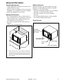
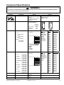
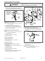
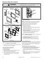
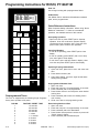
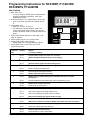
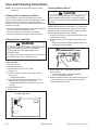
1
Service This manual is to be used by qualified appliance technicians only. Maytag does not assume any responsibility for property damage or personal injury for improper service procedures done by an unqualified person. This manual replace RS2240001 Revision 2. This Base Manual covers general information Commercial Microwave Oven RFS9B RFS9B RFS10S RFS10S RFS10SW2 RFS10SW2 RFS12MPS RFS12MPS RFS12S RFS12S RFS12SW2 RFS12SW2 P1324706M P1327707M P1324701M P1327708M P1324702M P1327709M P1324704M P1327711M P1324703M P1327710M P1324705M P1327712M Refer to individual Technical Sheet for information on specific models This manual includes, but is not limited to the following: 2002 Models are listed in bold. RCS10 RCS10 RCS10 RCS10D RCS10D RCS10MP RCS10MP RCS10MP RCS10MPS RCS10MPS RCS10MPS RCS10MPSED RCS10MPSED RCS10PBD RCS10PBD P1140411M P1324601M P1327703M P1152809M P1327701M P1140412M P1324602M P1327704M P1324901M P1324902M P1327705M P1324906M P1327706M P1324001M P1327702M 16021520 Revision 0 October 2002 Important Information Important Notices for Servicers and Consumers Maytag will not be responsible for personal injury or property damage from improper service procedures. Pride and workmanship go into every product to provide our customers with quality products. It is possible, however, that during its lifetime a product may require service. Products should be serviced only by a qualified service technician who is familiar with the safety procedures required in the repair and who is equipped with the proper tools, parts, testing instruments and the appropriate service information. IT IS THE TECHNICIANS RESPONSIBLITY TO REVIEW ALL APPROPRIATE SERVICE INFORMATION BEFORE BEGINNING REPAIRS. ! WARNING To avoid risk of severe personal injury or death, disconnect power before working/servicing on appliance to avoid electrical shock. To locate an authorized servicer, please consult your telephone book or the dealer from whom you purchased this product. For further assistance, please contact: Customer Service Support Center CAIR Center Web Site Telephone Number WWW.AMANA.COM ................................................ 1-800-843-0304 WWW.JENNAIR.COM ............................................. 1-800-536-6247 WWW.MAYTAG.COM ............................................. 1-800-688-9900 CAIR Center in Canada ........................................... 1-800-688-2002 Amana Canada Product ........................................... 1-866-587-2002 Recognize Safety Symbols, Words, and Labels ! DANGER DANGER—Immediate hazards which WILL result in severe personal injury or death. ! WARNING WARNING—Hazards or unsafe practices which COULD result in severe personal injury or death. ! CAUTION CAUTION—Hazards or unsafe practices which COULD result in minor personal injury, product or property damage. 2 16021520 Rev. 0 ©2002 Maytag Appliances Company Table of Contents Important Information .................................................. 2 Important Safety Information ....................................... 4 Grounding Instructions ............................................ 7 Servicing of Grounded Products ............................... 8 Wiring .................................................................... 8 Proper Grounding and Polarization of 120 Volts Wall Outlets ......................................... 8 Explanation ............................................................ 8 Test Procedures (2 Methods) ................................... 8 General Test Information .......................................... 8 General Information Unpacking Equipment ............................................. 9 Equipment Placement ............................................. 9 Radio Interference ................................................... 9 Oven Features ........................................................ 9 Model Identification ............................................... 10 Service................................................................. 10 Parts and Accessories .......................................... 10 Extended Service Plan .......................................... 10 Component Testing Procedures ................................ 11 Power Test ........................................................... 14 Service Information Proper Handling of Magnetron Tubes ...................... 15 Magnetron Failure Mode ........................................ 15 Radiation Leakage Test Equipment ........................................................... 16 Procedure For Measuring Radiation Leakage .......... 16 Measurement With the Outer Panel Removed ......... 16 Measurement With a Fully Assembled Oven ........... 16 Record Keeping and Notification After Measurement ............................................ 16 Troubleshooting Operating Instructions for NARDA 8110B Radiation Monitor ............................................... 17 Radiation Monitor .................................................. 17 Operating Instructions for Holaday HI1501, HI1510, and HI1710 ............................... 18 Troubleshooting Guide .............................................. 19 ©2002 Maytag Appliances Company Disassembly Procedures Outer Case Removal ............................................. 21 Start Switch and Button ......................................... 21 Control Assembly (painted models) ........................ 21 Control Assembly (stainless steel model) ............... 21 Removal of H.V. Transformer, Capacitor, Diode (Rectifier), Magnetron ............................... 22 Removal of Outer Case Foot .................................. 22 Blower Motor or Wheel .......................................... 22 Splatter Shield ...................................................... 22 Antenna and Cradle .............................................. 22 Magnetron Thermal Cut-Out (TCO) ......................... 23 Cavity Thermal Fuse ............................................. 23 Door Disassembly ................................................ 23 Interlock Switch Assembly .................................... 24 Tray Replacement ................................................. 24 Oven Light Removal .............................................. 24 Appendix A Programming Operating Instructions RCS10, P1140411M .......................................... A-2 RCS10MP, P1140412M ..................................... A-3 RCS10MPS, P1324901M .................................. A-3 RCS10D ........................................................... A-6 RCS10PBD ...................................................... A-6 RFS9B ............................................................. A-7 RCS10, P1324601M, P1327703M ...................... A-7 RCS10MP, P1324602M, P1327704M ................. A-7 RCS10MPS, P1324902M, P1327705M ............... A-7 RFS10S, P1324701M, P1327708M .................... A-7 RFS12MPS, P1324704M, P1327711M ............... A-7 RFS12S, P1324703M, P1327710M .................... A-7 RFS10SW2, P1324702M, P1327709M ............. A-12 RFS12SW2, P1324705M, P1327712M ............. A-12 Appendix B Care and Cleaning Instructions Cleaning Interior, Exterior, and Door .................... B-2 Changing Oven Light Bulb .................................. B-2 Cleaning Splatter Shield .................................... B-2 Cleaning Discharge Air Vents ............................. B-3 Cleaning Air Intake Filter (RFS models only) ....... B-3 16021520 Rev. 0 3 Important Safety Information ! WARNING Read the following information to avoid possible exposure to microwave radiation: The basic design of the Amana Microwave Oven makes it an inherently safe device to both use and service. However, there are some precautions which should be followed when servicing the Radarange to maintain this safety. These are as follows: 1. Always operate the unit from an adequately grounded outlet. Do not operate on a two-wire extension cord. 8. Do not for any reason defeat the interlock switches there is not valid reason for this action at any time; nor will it be condoned by Amana. 2. Before servicing the unit (if unit is operable) perform the microwave leakage test. 9. IMPORTANT: Before returning a unit to a customer, be sure to check for proper switch interlock action. 3. The oven should never be operated if the door does not fit properly against the seal, the hinges or hinge bearings are damaged or broken; the choke is damaged, (pieces missing, etc.); or any other visible damage can be noted. Check the choke area to ensure that this area is clean and free of all foreign matter. 4. If the oven operates with the door open and produces microwave energy, take the following steps: A. Tell the user not to operate the oven. B. Contact Maytag Amana Manufacturing immediately. 5. Always have the oven disconnected when the outer case is removed except when making the "live" tests called for in the Service Manual. Do not reach into the equipment area while the unit is energized. Make all connections for the test and check them for tightness before plugging the cord into the outlet. 6. Always ground the capacitors on the magnetron filter box with an insulated-handle screwdriver before working in the high voltage area of the equipment compartment. Some types of failures will leave a charge in these capacitors and the discharge could cause a reflex action which could make you injure yourself. 7. Always remember that in the area of the transformer there is HIGH VOLTAGE. When the unit is operating keep this area clear and free of anything which could possibly cause an arc or ground, etc. 4 10. Before returning a unit to a customer, be sure that the door spacing is reasonably uniform along the top, bottom, and sides, and that it measure 1/8" or less. 11. The Amana Microwave Oven should never be operated with any components removed and/or bypassed or when any of the safety interlocks are found to be defective, or when any of the seal surfaces are defective, missing, or damaged. 12. All Amana microwave ovens meet all requirements of the radiation control for Health and Safety Act of 1968. Due to measurement uncertainties, the maximum leakage for the field will be 4mw/cm2. 13. To ensure that the unit does not emit excessive microwave leakage and to meet the Department of Health and Human Services guidelines, check the oven for microwave leakage using the Narda model 8100, 8200 Holaday HI1500, HI1501, or Simpson 380M leakage monitor as outlined in the instruction. The maximum leakage level allowed when following those instructions is 4mw/cm2. 14. If servicer encounters an emission reading over 4mw/cm2, the servicer is to cease repair and contact the Amana Service Department immediately for further direction. Amana Manufacturing will contact the proper Government Agency upon verification of the test results. 16021520 Rev. 0 ©2002 Maytag Appliances Company Important Safety Information Recognize this symbol as a SAFETY message ! WARNING When using electrical equipment, basic safety precautions should be followed to reduce the risk of burns, electrical shock, fire, or injury to persons. 1. READ all instructions before using equipment. 2. READ AND FOLLOW the specific “PRECAUTIONS TO AVOID POSSIBLE EXPOSURE TO EXCESSIVE MICROWAVE ENERGY”. 3. This equipment MUST BE GROUNDED. Connect only to properly GROUNDED outlet. See “GROUNDING INSTRUCTIONS”. 4. Install or locate this equipment ONLY in accordance with the installation instructions in this manual. 5. Some products such as whole eggs and sealed containers, for example, closed glass jars may explode and SHOULD NOT be HEATED in this oven. 6. Use this equipment ONLY for its intended use as described in this manual. Do not use corrosive chemicals or vapors in this equipment. This type of oven is specifically designed to heat or cook. It is not designed for industrial or laboratory use. 7. As with any equipment, CLOSE SUPERVISION is necessary when used by CHILDREN. 8. DO NOT operate this equipment if it has a damaged cord or plug, if it is not working properly, or if it has been damaged or dropped. 9. This equipment, including power cord, must be serviced ONLY by qualified service personnel. Special tools are required to service equipment. Contact nearest authorized service facility for examination, repair, or adjustment. 10. DO NOT cover or block filter or other openings on equipment. 11. DO NOT store this equipment outdoors. DO NOT use this product near water, for example, near a kitchen sink, in a wet basement, or near a swimming pool, and the like. 12. DO NOT immerse cord or plug in water. 13. Keep cord AWAY from HEATED surfaces. 14. DO NOT let cord hang over edge of table or counter. 15. See door cleaning instructions in “Care and Cleaning” section. 16. For commercial use only. ! CAUTION To reduce risk of fire in the oven cavity: a. DO NOT overcook food. Carefully attend equipment if paper, plastic, or other combustible materials are placed inside the oven to facilitate cooking. b. Remove wire twist-ties from paper or plastic bags before placing bag in oven. c. KEEP oven DOOR CLOSED, turn oven off, and disconnect the power cord, or shut off power at the fuse or circuit breaker panel, if materials inside the oven should ignite. Fire may spread if door is opened. d. DO NOT use the cavity for storage. DO NOT leave paper products, cooking utensils, or food in oven. SAVE THESE INSTRUCTIONS ©2002 Maytag Appliances Company 16021520 Rev. 0 5 Important Safety Information ! CAUTION To avoid risk of personal injury or property damage, observe the following: 1. Briskly stir or pour liquids before heating with microwave energy to prevent spontaneous boiling or eruption. Do not overheat. If air is not mixed into a liquid, liquid can erupt in oven or after removal from oven. 7. Do not use regular cooking thermometers in oven. Most cooking thermometers contain mercury and may cause an electrical arc, malfunction, or damage to oven. 8. Do not heat baby bottles in oven. 2. Do not deep fat fry in oven. Fat could overheat and be hazardous to handle. 3. Do not cook or reheat eggs in shell or with an unbroken yolk using microwave energy. Pressure may build up and erupt. Pierce yolk with fork or knife before cooking. 4. Pierce skin of potatoes, tomatoes, and similar foods before cooking with microwave energy. When skin is pierced, steam escapes evenly. 5. Do not operate equipment without load or food in oven cavity. 6. Use only popcorn in packages designed and labeled for microwave use. Popping time varies depending on oven wattage. Do not continue to heat after popping has stopped. Popcorn will scorch or burn. Do not leave oven unattended. 9. Do not use metal utensils in oven. 10. Never use paper, plastic, or other combustible materials that are not intended for cooking. 11. When cooking with paper, plastic, or other combustible materials, follow manufacturer's recommendations on product use. 12. Do not use paper towels which contain nylon or other synthetic fibers. Heated synthetics could melt and cause paper to ignite. 13. Do not heat sealed containers or plastic bags in oven. Food or liquid could expand quickly and cause container or bag to break. Pierce or open container or bag before heating. 14. To avoid pacemaker malfunction, consult physician or pacemaker manufacturer about effects of microwave energy on pacemaker. PRECAUTIONS TO AVOID POSSIBLE EXPOSURE TO EXCESSIVE MICROWAVE ENERGY a. DO NOT attempt to operate this oven with the door open since open-door operation can result in harmful exposure to microwave energy. It is important not to defeat or tamper with the safety interlocks. c. DO NOT operate the oven if it is damaged. It is particularly important that the oven door close properly and that there is no damage to the: (1) door (bent), (2) hinges and latches (broken or loosened), (3) door seals and sealing surfaces. b. DO NOT place any object between the oven front face and the door or allow soil or cleaner residue to accumulate on sealing surfaces. d. The oven should NOT be adjusted or repaired by anyone except properly qualified service personnel. SAVE THESE INSTRUCTIONS 6 16021520 Rev. 0 ©2002 Maytag Appliances Company Important Safety Information ! Grounding Instructions WARNING Precautions to be observed before and during servicing to avoid possible exposure to excessive microwave energy, or electrical shock disconnect power to oven. • Do not operate or allow oven to be operated with door open. • Make the following safety checks on all ovens to be serviced before activating the magnetron or other microwave source, and make repairs as necessary: • Interlock operation • Proper door closing • Seal and sealing surfaces (arcing, wear, and other damage) • Damage to or loosening of hinges and latches • Evidence of dropping or abuse • Before turning on microwave power for any service test or inspection within the microwave generating compartments, check the magnetron, waveguide or transmission line, and cavity for proper alignment, integrity, and connections. • Any failed or misadjusted components in the interlock, monitor, door seal, and microwave generation and transmission systems shall be repaired, replaced or adjusted by procedures described in this manual before oven is released to the consumer. • Check microwave leakage to verify compliance with the federal performance standard should be performed on each oven prior to release to the consumer. ! WARNING To avoid risk of electrical shock, injury or death; make sure these grounding instructions are followed. ! Do not remove grounding prong when installing grounded appliance in a home or business that does not have three wire grounding receptacle, under no condition is grounding prong to be cut off or removed. It is the personal responsibility of the consumer to contact a qualified electrician and have properly grounded three prong wall receptacle installed in accordance with appropriate electrical codes. ! WARNING To avoid the risk of electrical shock or death, do not alter the plug. ! WARNING To avoid the risk of electrical shock or death, this equipment must be grounded. This equipment MUST be grounded. In the event of an electrical short circuit, grounding reduces the risk of electric shock by providing an escape wire for the electric current. This oven is equipped with a cord having a grounding wire with a grounding plug. The plug must be plugged into an outlet that is properly installed and grounded. Consult a qualified electrician or servicer if grounding instructions are not completely understood, or if doubt exists as to whether the equipment is properly grounded. Do not use an extension cord. If the product power cord is too short, have a qualified electrician install a threeslot receptacle. This oven should be plugged into a separate 60 hertz circuit with the electrical rating as shown in the appropriate drawing. Models operate with a 120 supply voltage. When a microwave oven is on a circuit with other equipment, an increase in cooking times may be required and fuses can be blown. NEMA 5-15R/5-15P 120V–15AMP NEMA 5-20R/5-20P 120V–20AMP ©2002 Maytag Appliances Company WARNING 16021520 Rev. 0 7 Important Safety Information Servicing of Grounded Products Explanation The standard accepted color coding for grounding wires is GREEN or GREEN WITH YELLOW STRIPE. These ground leads are NOT to be used as current carrying conductors. It is extremely important that the technician replace any and all grounds prior to completion of the service call. Under no condition should ground wire be left off causing a potential hazard to technicians and consumer. Polarization–This means that the larger slot must be neutral and the small slot must be hot (live). Mispolarized–The outlet is miswired so that the larger slot is hot (live) and the smaller slot is neutral. Grounded–This means the round hole connection is connected to earth ground through a connection to the main power panel. Ungrounded–The round hole connection is not complete to earth ground and/or the main power panel. Wiring A good service practice is never route wiring over terminals and/ or sharp edges. This applies to any wiring without regard to the circuit voltage. Wire installation material and thickness is designed and regulated for electrical spacing purpose only, but cannot always be relied upon because of possible cuts and/or abrasions, which can occur during servicing. ! WARNING To avoid risk of electrical shock, personal injury or death; verify the oven is properly grounded and polarized. Test Procedures (2 Methods) Method #1 Purchase and use a ground monitor available under Amana Part Number R0193001 or it can be purchased locally. The lamps inside the monitor indicate a correctly or incorrectly wired outlet by instructions imprinted on the monitor body. Method #2 Voltmeter - (Use scale over 125 Volts A.C.) • Test A - "H" to "N" must indicate line voltage. • Test B - "H" to "G" must indicate line voltage. • Test C - "N" to "G" must indicate zero (0) volts. Proper Grounding and Polarization of 120 Volts Wall Outlets If "N" to "G" indicates line voltage the outlet is improperly polarized. For the safety of our customers and the service technician ALL appliances have a three–prong power cord and MUST be connected to a properly polarized and grounded wall outlet. If "H" to "G" indicates zero (0) volts the outlet is not grounded. This information was written for those who do not understand grounding and polarization of a wall outlet. A 120 volt wall outlet must always be wired as shown below. Hot (H) - This slot is the smaller size and should always be hot (live) with respect to neutral (N) and ground(G). Neutral (N) - This slot is the larger of the two and should be neutral (dead) with respect to ground. H N G Ground (G) - The round hole connection is for the grounding circuit. Behind the cover plate a green wire should be connected to this terminal. ! CAUTION To avoid risk of electrical shock, personal injury or property damage; wiring changes or grounding of wall outlet are to be made only by a qualified electrician. General Test Information Most testing in the manual is conducted with an ohmmeter using a multiplier scale of X 10k (k–thousand ohms). When using this scale, it is important that your fingers do not touch the metal parts of the test probes. To do so will give a false indication of the ohm reading. 8 16021520 Rev. 0 ©2002 Maytag Appliances Company General Information Unpacking Equipment Radio Interference • Inspect equipment for damage such as dents in door or dents inside oven cavity. • Report any dents or breakage to source of purchase immediately. Do not attempt to use oven if damaged. • Remove all materials from oven interior. Microwave operation may cause interference to radio, television, or similar equipment. Reduce or eliminate interference by doing the following: Equipment Placement • Do not install equipment next to or above source of heat, such as pizza oven or deep fat fryer. This could cause microwave oven to operate improperly and could shorten life of electrical parts. • Do not block or obstruct air filter. Allow access for cleaning. • Install on level countertop surface. • Clean door and sealing surfaces of oven according to instructions in “Care and Cleaning” section. • Place radio, television, etc. as far as possible from oven. • Use a properly installed antenna on radio, television, etc. to obtain stronger signal reception. Oven Features Removable Splatter Shield (Not Shown) A A Oven Door Window and Interior Light A Oven Display Oven Control Pads Filter (some models) A—Allow at least 1½ inches / 3.81 centimeters of clearance around top and sides of equipment. Proper air flow around equipment cools electrical components. With restricted air flow, oven may not operate properly and life of electrical parts is reduced. ©2002 Maytag Appliances Company 16021520 Rev. 0 9 General Information Model Identification Parts and Accessories Complete registration card and promptly return. If registration card is missing: Purchase replacement parts and accessories over the phone. To order accessories for your product call: • For Amana product call 1-800-843-0304 or visit the Web Site at www.amana.com • For Maytag product call 1-800-688-9900 or visit the Web Site at www.maytag.com • For Jenn-Air product call 1-800-536-6247 or visit the Web Site at www.jennair.com • For product inCanada call 1-866-587-2002 or visit the Web Sites at www.amana.com or www.maytag.com or www.jennair.com When contacting provide product information located on rating plate. Record the following: • For Amana product call 1-877-232-6771 or visit the Web Site at www.amana.com • For Maytag/Jenn-Air product call 1-800-462-9824 or visit the Web Site at www.maytag.com or www.jennair.com • For product inCanada call 1-866-587-2002 or visit the Web Sites at www.amana.com or www.maytag.com or www.jennair.com Model Number: Manufacturing Number: Serial or S/N Number: Date of purchase: Dealer’s name and address: • Asure™ Extended Service Plan is specially designed to supplement Amana’s strong warranty. This plan covers parts, labor, and travel charges. Call 1-866-232-6244 for information. • Dependability Plus SM Extended Service Plan is specially designed to supplement Maytag’s and Jenn-Air’s strong warranty. This plan covers parts, labor, and travel charges. Call 1-800-925-2020 for information. _____________________ _____________________ _____________________ _____________________ _____________________ Service Keep a copy of sales receipt for future reference or in case warranty service is required. To locate an authorized servicer: Extended Service Plan We offer long-term service protection for this new oven. • For Amana product call 1-800-628-5782 or visit the Web Site at www.amana.com • For Maytag/Jenn-Air product call 1-800-462-9824 or visit the Web Site at www.maytag.com or www.jennair.com • For product inCanada call 1-866-587-2002 or visit the Web Sites at www.amana.com or www.maytag.com or www.jennair.com Warranty service must be performed by an authorized servicer. We also recommend contacting an authorized servicer, if service is required after warranty expires. 10 16021520 Rev. 0 ©2002 Maytag Appliances Company Component Specifications ! WARNING To avoid risk of electrical shock, personal injury or death; disconnect power to oven and discharge capacitor before servicing, unless testing requires power. Illustration Component Thermal cutout Diode Testing Disconnect all wires from TCO. Measure resistance across terminals. Cavity TCO Magnetron TCO Magnetron TCO Discharge Capacitor Remove diode lead from capacitor and connect ohmmeter. Reverse leads for second test. Discharge Capacitor Capacitor Remove wires from capacitor terminals and connect ohmmeter, set on highest resistance scale to terminals. Also check between each terminal and capacitor case. Discharge Capacitor Magnetron Remove wires from magnetron and connect ohmmeter to terminals. Also check between each terminal and ground. Blower motor Transformer Filament 5 6 6 1 4 Primary 5 2 2 H.V. Secondary 4 1 RFS9B, RCS10*, RFS10* Transformer Filament 5 6 6 1 4 Primary 5 2 2 Opens at 243°F (117°C) Closed at 150°F and open at 250°F Closed at 180°F and open at 280°F Infinite resistance should be measured in one direction and 50KΩ or more in the opposite direction. NOTE: Ohmmeter must contain a battery of 6 volts minimum. Between Terminals: Meter should momentarily deflect towards zero then return to over 5 MΩ. If no deflection occurs, or if continuous deflection occurs, replace capacitor. Terminal to Case: Infinite resistance Between Terminals: Less than 1 Ω Each terminal to ground measures Infinite resistance. Note: This test is not conclusive. If oven does not heat and all other components test good replace the magnetron and retest. Remove all wires from motor. Measure resistance across coil RFS12* Results H.V. Secondary 4 Approximately 14 Ω Discharge Capacitor Remove all wires from terminals. Measure resistance from: 1 to 2 Terminal 5 to 6 Terminal 4 to Ground screw on transformer stack Less than <1 Ω Less than <1 Ω Approximately 78 Ω Discharge Capacitor Remove all wires from terminals. Measure resistance from: 1 to 2 Terminal 5 to 6 Terminal 4 to Ground screw on transformer stack Less than <1 Ω Less than <1 Ω Approximately 138 Ω 1 6 minute timer 2 1 3 4 5 3 ©2002 Maytag Appliances Company Remove leads from timer contact terminals. Measure resistance of following terminals: 1 to 2Timer in OFF position 1 to 2Timer in ON position 4 to 5Timer in OFF or ON position 16021520 Rev. 0 If timer does not indicate readings below, replace timer. Infinite Ω Approximately <1 Ω Approximately 5.8 kΩ (timer motor) 11 Component Specifications ! WARNING To avoid risk of electrical shock, personal injury or death; disconnect power to oven and discharge capacitor before servicing, unless testing requires power. Illustration Component Interlock switch assembly 7 8 2 3 5 4 7 8 2 3 5 4 Testing Disconnect wires to switch. Results With door open measure resistance from: Terminal 7 to 8 Monitor Terminal 4 to 5 Primary Terminal 2 to 3 Secondary Indicates continuity Infinite Ω Infinite Ω With door closed measure resistance from: Terminal 7 to 8 Monitor Terminal 4 to 5 Primary Terminal 2 to 3 Secondary Infinite Ω Indicates continuity Indicates continuity After verifying or replacing the module, reconnect wires to switch and check operation of monitor circuit before operating the oven. HV/LV. board Internal Display Graphics Pin # 1 P2 RCS10 P1140411M RCS10MP P1140412M RCS10MPS P1324901M At 8 pin connector: Pin 1 (orange) to Pin 3 (white) Relay 2 (blower relay) Terminal A (brown) to terminal B (black) Relay 1 (cook relay) Terminal B (black) to terminal C (blue) A B C D E Triac Terminal D (red) to terminal E (orange) P1 Pin # 1 HV/LV. board Internal Display Graphics Pin # 1 P3 P1 RFS10SW2 RFS12SW2 RFS12MPS RFS12S At 8 pin connector: Pin 1 (black) to Pin 3 (white) Relay 2 (blower relay) Terminal C (black) to terminal J (brown) Relay 1 (cook relay) Terminal F (black) to terminal K (blue) A B C J E F Triac Terminal A (gray) to terminal B (red) Pin # 1 K P2 H HV/LV. board Internal Display Graphics Pin # 1 P3 P1 A B C J E F Pin # 1 K P2 H Fault Codes 12 1324706M P1327707M RCS10 P1324601M P1327703M RCS10MP P1324602M P1327704M RCS10MPS P1324902M P1327705M RCS10MPSED P1324906M P1327706M RFS10S P1324701M P1327708M At 8 pin connector: Pin 1 (black) to Pin 3 (white) RFS9B Display Relay 2 (cook relay) Disconnect wires to terminals F and K and tape wires apart. Set multimeter to “Ohms” and attach meter leads to F and K. Terminal F (orange) to terminal K (red) Relay 1 (blower relay) Terminal C (black) to terminal J (blue) Line voltage input to control transformer Cook condition0 volts Idle conditionLine voltage Cook condition0 volts Idle conditionLine voltage Cook condition1.1 VAC Idle condition0 volts Line voltage input to control transformer Cook condition0 volts Idle conditionLine voltage Cook condition0 volts Idle conditionLine voltage Cook condition0.9 VAC Idle condition0 volts Line voltage input to control transformer Cook conditionIndicates continuity Idle conditionInfinite Ω Cook condition0 volts Idle conditionLine voltage F1 − F2 − F3 − F4 − F5 − F6 − ........................................................... ........................................................... ........................................................... ........................................................... ........................................................... ........................................................... 16021520 Rev. 0 Replace H.V. / L.V. Board Replace H.V. / L.V. Board Replace H.V. / L.V. Board Replace H.V. / L.V. Board Replace Touch Panel Replace H.V. / L.V. Board ©2002 Maytag Appliances Company Component Specifications ! WARNING To avoid risk of electrical shock, personal injury or death; disconnect power to oven and discharge capacitor before servicing, unless testing requires power. 1 2 3 4 5 6 7 8 9 10 11 The following are Hidden Keypads: ENABLE SECONDS HOLD/MIN Keyboard assembly Continuity is indicated as 100 Ω and below. RCS10 P1324601M P1327703M RCS10MP P1324602M P1327704M RCS10MPS P1324902M P1327705M RCS10MPSED P1324906M P1327706M RFS10S P1324701M P1327708M RFS10SW2 P1324702M P1327709M RFS12MPS P1324704M P1327711M RFS12S P1324703M P1327710M RFS12SW2 P1324705M P1327712M Lamp receptacle Lamp 41 W Wire Harness ©2002 Maytag Appliances Company 1 2 3 4 5 6 7 8 9 10 11 Test continuity of receptacle terminals. Measure resistance of filament. Test continuity of wires 16021520 Rev. 0 0 1 P1140411M RCS10MP P1140412M RCS10MPS P1324901M RFS9B P1324706M P1327707M 8 RCS10 6 Continuity is indicated as 100 Ω and below. O Te 4 Keyboard assembly 2 Coil-115 VAC Contacts # 1 Contact # 2 AROMAT Terminals 5&6 3&4 1&2 5 Relay 6 NC COM-NO=Closed COM-NO=Open 4 NO Results 3 COM Testing Switch connection in following positions: Engaged−(Push in and hold) Disengaged−(Normal position) Refer to wiring diagram for terminal identification. 2 Component Start switch 1 Illustration AROMAT Pad DEFROST MEDIUM MED-HIGH TIME ENTRY RESET START ENABLE SECONDS HOLD/MIN 1 2 3 4 5 6 7 8 9 0 Pad DEFROST MEDIUM MED-HIGH TIME ENTRY STOP/RESET START HOLD X2 1 2 3 4 5 6 7 8 9 0 OMRON Trace Measurement 3&4 Continuity 3&5 Continuity 3&6 Continuity 3&7 Continuity 3&8 Continuity 3&9 Continuity 5&9 Continuity 6&9 Continuity 8&9 Continuity 7&8 Continuity 7&9 Continuity 5&8 Continuity 6 & 10 Continuity 7 & 10 Continuity 5 & 10 Continuity 8 & 10 Continuity 4 & 10 Continuity 5&7 Continuity 6&7 Continuity Trace Measurement 6&7 Continuity 5&7 Continuity 4&7 Continuity 7&8 Continuity 4&8 Continuity 4&9 Continuity 3&8 Continuity 6&8 Continuity 8 & 10 Continuity 7 & 10 Continuity 6 & 10 Continuity 5 & 10 Continuity 4 & 10 Continuity 3 & 10 Continuity 8&9 Continuity 7&9 Continuity 6&9 Continuity 5&9 Continuity Indicates continuity with bulb installed. Approximately 28 Ω Indicates continuity 13 Component Specifications ! WARNING To avoid risk of electrical shock, personal injury or death; disconnect power to oven and discharge capacitor before servicing, unless testing requires power. Power Test (Traditional Test Method) Test equipment required is Amana power test kit R0157397(Fahrenheit), or Menumaster power test kit M95D5 (Celsius). 1. Fill the plastic container to the bottom of the 1000 ml. line with cool tap water. 2. Using the thermometer; stir the water, measure and record the water temperature. Initial water temperature should be approximately 60°F (20°C). 3. Place container on the center of the oven shelf and heat the water for 62 seconds. NOTE: Use a watch second hand, not the oven timer. 4. Stir the water, measure and record the temperature of the water after heating time is complete. 5. Subtract the starting water temperature (Step 2), from the ending water temperature (Step 4), to obtain the temperature rise. 6. See the Temperature Chart provided below. NOTES: •The IEC-705 test method requires precision measurements and equipment. It is not practical to perform the IEC test in the field. To convert the traditional power test results to the approximate IEC-705 rating, take the traditional power test results and add 100 watts per magnetron for the unit being tested. Example: 930 watts output using the traditional power test for model RCS10MP + 100 watts (1 magnetrons X 100 watts) 1030 Approximate IEC-705 results •Always perform power test three times for accuracy, changing the water after each test is performed. •Variation or errors in the test procedure will cause a variance in the temperature rise. Additional power tests should be made if temperature rise appears marginal. •Low line voltage will cause lower temperature rise. Temperature Chart ONE MINUTE, THREE SECONDS run time chart for units less than 1550 Watts cooking power ∆T (°F) Cooking Power Output ∆T (°F) 12 13 14 15 16 17 18 19 20 21 464 504 542 580 620 659 697 736 775 814 22 23 24 25 26 27 28 29 30 31 14 Cooking Power Output 852 891 930 969 1007 1046 1085 1124 1162 1201 ∆T (°C) Cooking Power Output ∆T (°C) 7 8 9 10 11 12 13 14 490 560 630 700 770 840 910 980 15 16 17 18 16021520 Rev. 0 Cooking Power Output 1050 1120 1190 1260 ©2002 Maytag Appliances Company Service Information ! WARNING To avoid risk of electrical shock, personal injury, or death, disconnect power to oven and discharge capacitor before servicing, unless testing requires it. Proper Handling of Magnetron Tubes ! CAUTION A magnetron tube, like a radio or television tube must be handled with a reasonable amount of care. When handling a tube, always handle by the housing only. Use caution not to touch or strike the ceramic portion at the top. The carton used to ship service replacement tubes is reusable. Magnetron Failure Modes Magnetron failures that have been identified are generally grouped into categories shown below. 1. Shorted Air - This is a case where the tube has had the vacuum envelope destroyed and air has entered the tube. This will cause internal arcing and high secondary current if high voltage is applied. 2. Open Heater (Filament) - Can be determined by a ohmmeter when transformer leads are disconnected. Resistance is normally less than one ohm; filament does not short internally. Any tube removed should be checked since usage tends to make the filament more fragile. Later handling and shipping may open the filament and thereby mask the true failure mode when checked at the factory. 3. Low Power - Caused by “wearout” of the emission characteristics of the directly heated cathode. Symptoms are: (1) tube current will take longer to get to operating point than a new tube (normally about 2 - 3 seconds), (2) tube current does not get high enough to cause the tube to oscillate with normal line voltage, (3) oven produces low power into a load, two-thirds or less than normal. 4. Physical Damage - Caused by mishandling of magnetron tube. R.F. Capacitors - May short to chassis. This condition will also cause loss of high voltage. Output Antenna Ceramic Fins Anode Block Magnet Terminals/R.F. Capacitors Not Replaceable Serial Number ©2002 Maytag Appliances Company 16021520 Rev. 0 15 Radiation Leakage Testing ! WARNING To avoid risk of electrical shock, personal injury, or death, disconnect power to oven and discharge capacitor before servicing, unless testing requires it. ! Measurement with the Outer Panel Removed WARNING Check for radiation leakage after servicing. Should the leakage be more than 4 mW/cm2 inform Maytag immediately. After repairing or replacing any radiation safety device, keep a written record for future reference, as required by D.H.H.S. and HEW regulations. This requirement must be strictly observed. In addition, the leakage reading must be recorded on the service repair ticket while in the customer’s home. ! WARNING Avoid contacting any high voltage components. Whenever you replace the magnetron, measure for radiation leakage before the outer panel is installed and after all necessary components are replaced or adjusted. Special care should be taken in measuring around the magnetron. Equipment • Electromagnetic radiation monitor • 600 cc glass beaker Measurement with a Fully Assembled Oven Procedure for Measuring Radiation Leakage Note before measuring: • Do not exceed meter full scale deflection. Leak monitor should initially be set to the highest scale. • To prevent false readings the test probe should be held by the grip portion of the handle only. • The scan speed is equal to one inch per antenna revolution or one inch per second if antenna speed is unknown. • Areas to be checked are all door seal areas and any venting parts. • Leakage with the outer panel removed ...4mW/cm2 or less. • Leakage for fully assembled oven with door normally closed ...4 mW/cm2 or less. • Leakage for a fully assembly oven (before the latch switch (primary) is interrupted) while pulling the door ... 4 mW/cm2 or less. After all components including the outer panel are fully assembled, measure for radiation leakage around the door periphery, the door viewing window, the exhaust opening, and air inlet openings. Record Keeping and Notification After Measurement 1. After any adjustment or repair to a microwave oven, a leakage reading must be taken. Record this leakage reading on the repair ticket even if it is zero. 2. A copy of the repair ticket and the microwave leakage reading should be kept by the repair facility. 1. Pour 275 cc ±15 cc (9 oz ±1/2 oz) of 20°C ± 5°C (68°F ± 9°F) water in a beaker which is graduated to 600 cc and place the beaker in the center of oven. 2. Set the radiation monitor to 2450 MHz and use it following the manufacturer’s recommended test procedure to assure correct results. 3. While measuring the leakage, always use the two inch (5 cm) spacer supplied with the probe. 4. Press the start pad or turn on the timer and with the magnetron oscillating, measure the leakage by holding the probe perpendicular to the surface being measured. 16 16021520 Rev. 0 ©2002 Maytag Appliances Company Troubleshooting ! WARNING To avoid risk of electrical shock, personal injury, or death, disconnect power to oven and discharge capacitor before servicing, unless testing requires it. Operating Instructions for the Narda 8110B Radiation Monitor Purpose of the monitor is to check radiation leakage around the microwave oven door and other places where radiation could possibly occur. Radiation Monitor This instrument measures radiation leakage in milliwatts per square centimeters (mW/cm2). The probe should be used with 2" (5cm) cone spacer. 1 Water load of 275 cc. (approximately 1 /3 cup), is to be placed in the oven and used as a load during leakage test. Operate the instrument on its internal rechargeable battery or a 115 or 230 V power supply. It may also be charged from a 115 or 230 V 50 or 60 Hz power source. “Meter Response” switch should be set on fast position. Slow setting requires too long of a time to register. “Alarm” control should be set on 50 which sounds an audible alarm when the meter reads 50% of full scale deflection. This is to provide warning against high levels which may damage the instrument. “Range” switch may be used on the lower or higher meter scale. On an oven with an unknown leakage, use high scale first. Switch to low scale for low leakage. “Test” switch is used to check the battery and probe. If either is faulty, meter needle will not read above “Test Minimum” mark on the meter. Zero control is used to zero the needle. With probe and cone spacer plugged into the instrument, turn monitor on-off switch to the on position. Check battery and probe “Test” switch. If battery reading does not come up to “Test Minimum” setting, plug in AC cord. If probe test fails, do not use probe. Hold probe perpendicular to cabinet door. Place cone of probe on the door and/or cabinet-door seam and move along the seam. If leakage of the oven is unknown, move probe slowly. Any time the audible alarm sounds proceed with care in order not to exceed a full scale reading of the meter or remove the probe from the area of leakage. When testing near a corner or access area of the door, keep probe perpendicular to the areas making sure the probe end at the base of the cone does not get closer than 2” (5cm) to any metal. If it does, an erroneous reading may result. Always use the 2” (5cm) spacer with probe. Also, always proceed carefully in areas of high leakage or the probe can be accidentally burned-out. Rotating stirrer causes high peaks of energy. Although meter has averaging capabilities, probe will react instantaneously to peak power changes which will cause burn-out. If oven is likely to have a large amount of leakage approach the oven slowly with the probe, while observing meter. This is achieved by holding probe two or three feet from the oven and then moving toward oven surface or gap between the door and oven body while observing meter. When high leakage is expected, do not move probe horizontally along the oven surface, this could cause possible probe burnout. Greatest leakage is generally found at the corners. After maximum leakage is established to be within the meter scale range, then probe may be moved horizontally around door surface. NOTE: For further information see Amana Service Letters of the R-10, R-35, and R-59 Series and your Narda 8110B Instruction Manual. During usage, if probe becomes inoperative or disconnected, audio alarm will come on. Test probe must be held by the grip portion of the handle, otherwise false reading may result if operators hand is between the handle and probe. ©2002 Maytag Appliances Company 16021520 Rev. 0 17 Troubleshooting ! WARNING To avoid risk of electrical shock, personal injury, or death, disconnect power to oven and discharge capacitor before servicing, unless testing requires it. Operating Instructions for the Holaday HI1501, HI1510, and HI1710 Purpose of these monitors is to check radiation leakage around microwave oven door or other places where radiation could possibly occur. Instrument measures radiation leakage in milliwatts per square centimeters (mW/cm2). Probe should be used with the 2" (5 cm) cone spacer. Water load of 1 275 cc. (approximately 1 /3 cup), is to be placed in the oven and used as a load during leakage tests. Operate the instrument on its internal 9 Volt battery power supply. “Range” switch is used on low and high while using test probe. On an oven with an unknown leakage, use high scale then switch to low scale and test for low leakage. “Bat Test” switch is used to check the battery and probe on the Holaday Instruments. If either is faulty, meter needle will not read above “Test Minimum” or battery mark on meter. Holaday Instrument has a probe test switch position. Meter needle must indicate in the “OK probe test” portion of the scale when in this position. Zero control is used to zero the needle. “ON-OFF” switch provides a means of turning the operating voltage on or off. “Range Multiplier” switch provides a means of selection either 0-2 or 0-10 and 0-100 on the Holaday Instruments sensitivity ranges. Hold probe perpendicular to cabinet door. Place cone of probe on the door and/or cabinet door seam and move along the seam. If leakage of the oven is unknown, move probe slowly. Proceed with care in order not to exceed a full scale reading of meter. When testing near a corner or access area of door, keep probe perpendicular to the areas making sure probe end at the base of the cone does not get closer than 2” (5cm) to any metal. If it does, an erroneous reading may result. Always use the 2” (5cm) spacer with probe. Also, always proceed carefully in areas of high leakage or probe can be accidentally burned-out. Rotating antenna causes high peaks of energy. Although meter has averaging capabilities, probe will react instantaneously to peak power changes which will cause burn-out. NOTE: For further instructions see Amana Service Letters of the R-10, R-35, and R-59 of your Instrument Instruction Manual. NOTE: Simpson Electric Company Model 380M may also be used by using the above instructions for guideline and the 380M Instruction Manual. Test probe must be held by the grip portion of the handle, otherwise a false reading may result if operators hand is between the handle and probe. If oven is likely to have a large amount of leakage, approach oven slowly with the probe, while observing meter. This is achieved by holding the probe two or three feet from oven surface or gap between door and oven body while observing meter. When high leakage is expected, do not move probe horizontally along the oven surface. This could cause possible probe burn-out. Greatest leakage is generally found at the corners. After maximum leakage is established to be within the meter scale range, then probe may be moved horizontally around the door surface. 18 16021520 Rev. 0 ©2002 Maytag Appliances Company Troubleshooting Guide ! CAUTION All repairs as described in this section are to be performed only after the listed caution procedures listed below have been followed. • • • • Check grounding before checking for trouble. Be careful of the high voltage circuit. Discharge high voltage capacitor by shorting across terminals with screwdriver. When checking the continuity of the switches or the high voltage transformer, disconnect one lead wire from these parts and then check continuity with the AC plug removed. To do otherwise may result in a false reading or damage to your meter. • Do not touch any parts of the circuitry on the digital programmer circuit since static electric discharge may damage this control panel. Always touch yourself to ground while working on this panel to discharge any static charge in your body. • 120 VAC is present in the digital programmer circuit (Terminals of power relay B and primary circuit of low voltage transformer). When trouble shooting, be cautious of possible electrical shock hazard. Use of the Schematic and/or Wiring Diagrams will assist the technician on the following component checks. An Ohmmeter is required for most tests with a Multiplier Scale of X 1OK (k - thousand ohms). Test procedures will be found elsewhere in this manual. 1. 2. Condition No voltage at outlet. Voltage available to outlet. No components operating (including oven light). 3. Internal 20, 25 or 30 amp line fuse open. NOTE: If line fuse is open, the interlock switch assembly must be replaced, even if another component caused the fuse to open. Warranty claims involving fuse replacement will only be paid if switch assembly is replaced along with the fuse. Possible Causes • Line fuse open (external). Check for overload circuit. • Open power cord. • Failed terminal and/or wiring. • Open line fuse. See Condition # 3. • Open cavity thermal fuse. • Open magnetron TCO. • Interlock switch contacts open. • Inoperative p.c. board or electro-mechanical timer. 1. Failed terminal and/or wiring in 120 volt circuit of unit. 2. Shorted component in 120 volt circuit of unit. 3. Interlock switch assembly (test). 4. Replace fuse, if fuse blows quickly DO NOT proceed with step 5: recheck steps 1, 2, and 3. 5. Check amperes and/or wattage compare to Specifications Sheet (page 9). 6. If fuse blows after running a few seconds, disconnect power cord, disconnect and tape apart high voltage transformer primary wires, reconnect power cord. 7. If fuse does not open, disconnect power cord, and check H.V. components and wiring. 8. If fuse opens, check 120 volt section for loose connections or grounded wires. The timer, light and motor by themselves draw less than 1 Ampere. If the unit opens a fuse while the transformer is disconnected, there are usually burned areas visible. NOTE: When taking voltage measurements to the transformer the 120 V supply leads must be connected to the transformer terminals. The Voltage reading should then be taken with the voltmeter leads also connected to these terminals. ©2002 Maytag Appliances Company 16021520 Rev. 0 19 Troubleshooting Guide 4. Condition Oven light, triac, timer, and blower motor operate. Oven does not cook. No voltage at power transformer primary leads (120V). See NOTE. Caution: All other transformer leads are high voltage. 5. Same condition as # 4, but voltage is available at power transformer primary (120 VAC). See NOTE. 6. All oven components operate, unit cooks slowly, all modes. 7. Oven cooks food unevenly. 8. Control will not accept input. 9. Unit thumps at reduced power levels. Possible Causes • Failed wiring and/or terminal. • Inoperative interlock switch assembly. • Inoperative P.C. Board. • Failed terminal and/or wiring in high voltage section. • Failed H.V. transformer. • Failed diode. • Failed capacitor. • Failed magnetron. 1. Run Oven Performance Tests, if okay, customer education. 2. Check voltage at outlet, if low, customer education. 3. Check amperes and/or wattage, compare to Specification Sheet (refer to Technical Sheet). 4. Check tray and seal. If food debris has accumulated under ceramic tray, this debris will absorb microwave energy and affect performance test results. 5. If above checks are acceptable, replace tube. • Customer is not following cookbook instructions, customer education. • Rotating antenna not turning, check mounting parts for grease or burrs. This may also indicate incorrect air flow due to foam gasket out of place, failed blower motor, failed blower wheel or interference with splatter shield. NOTE: The antenna will not rotate when the splatter shield or outer case are removed. • Check wiring to interlock and the interlock switch contacts. • Inoperative keyboard. • Inoperative p.c. board. • Control triac is misfiring, replace p.c. board. NOTE: When taking voltage measurements to the transformer the 120 V supply leads must be connected to the transformer terminals. The Voltage reading should then be taken with the voltmeter leads also connected to these terminals. 20 16021520 Rev. 0 ©2002 Maytag Appliances Company Disassembly Procedures ! To avoid the risk of electrical shock, personal injury, or death, disconnect power to oven and discharge the capacitors before following any disassembly procedure. WARNING Outer Case Removal Control Assembly (painted models) 1. Remove screws securing outer case to the oven. 1. Disconnect power to oven and open door. 2. Using the Amana R0193557 escutheon removal tool, insert the right angle edge under the left side of the control escutcheon 1.5" from top and carefully pull back to release tabs from control assembly. 3. Remove screws securing control assembly to oven. 4. Disconnect wiring attached to control assembly components. 5. Reverse procedure to reassemble. Timer control assembly Escutcheon removal tool Escutcheon 2. Pull back on outer case and lift off. ! CAUTION During disassembly some foam gaskets may require removal. These components must be replaced for proper circulation of air over the components and through the oven cavity. Start Switch and Button (some models) 1. Remove outer case to gain access to switch. 2. Disconnect wires from switch. To remove button and start switch assembly: 3. Remove escutcheon. 4. Remove dial knob to release thinplate. 5. Using caution to prevent damage to indicator light, carefully rotate thinplate counterclockwise to gain access to start button and to the screws securing start switch assembly. 6. Reverse procedures to reassemble. Control Assembly (stainless steel models) 1. Disconnect power to oven. 2. Insert small bladed screwdriver in the service slot. Push down on the retainer clip and tilt escutcheon forward, lift, and remove. NOTE: Removal of outer case will facilitate removal of timer wiring and components, but is not necessary in all cases. Escutcheon bracket Service slot Escutcheon ©2002 Maytag Appliances Company 16021520 Rev. 0 Timer control assembly 21 Disassembly Procedures ! To avoid the risk of electrical shock, personal injury, or death, disconnect power to oven and discharge the capacitors before following any disassembly procedure. WARNING Removal of H.V. Transformer, Capacitor, Diode (Rectifier), Magnetron 10.Reverse procedure to reassemble. 1. Remove outer case. Ground magnetron terminals to magnetron housing with an insulated handle screwdriver by touching the metal shaft first to the magnetron housing, then to the magnetron tube terminals. 2. Remove component mounting screw(s) and disconnect wiring. Blower motor NOTE: When replacing H.V. components, route H.V. wires at least 1/4" from all grounded surfaces to prevent arcing. Blower wheel Blower scroll Push clip Removal of Outer Case Foot ! CAUTION To avoid possible excessive leakage it is mandatory the Amana part number A4539625 rivet be used to mount the unit feet. Do not substitute any other part. 1. Disconnect power to oven. 2. Place oven on its back and remove the plug button from center of the foot with a small screwdriver. Scroll bottom bracket Splatter Shield NOTE: Be careful not to bend antenna when removing splatter shield. Shield snaps into a lip in front of the oven and three slots in the back. 1. Place your thumbs in the two indentations in front of the shield. 2. Press lightly towards the back and carefully lower shield away from antenna. 3. Pull shield out of the back slots and out of the oven. Foot Rivet Plug button 3. Drill out rivet (Amana part number A4539625) to remove the foot. Splatter shield Blower Motor or Wheel NOTE: Blower wheel has a "D" type hole in hub and clip on end of motor shaft. 1. 2. 3. 4. 5. 6. 7. 8. 9. 22 Disconnect power to oven. Remove outer case. Disconnect wiring from blower motor. Remove screw from metal scroll bottom to partition. Remove screws from base pan bottom to plastic scroll legs. Slide scroll discharge snout from partition and lift scroll assembly from unit. Unsnap metal bottom from scroll. Remove blower wheel clip and wheel. Remove motor mounting screws from scroll. Antenna and Cradle NOTE: Antenna assembly is mounted in a cradle. The antenna is located on a tower in the middle of the cradle. 1. Remove outer case and splatter shield. 16021520 Rev. 0 ©2002 Maytag Appliances Company Disassembly Procedures ! To avoid the risk of electrical shock, personal injury, or death, disconnect power to oven and discharge the capacitors before following any disassembly procedure. WARNING 2. Remove two mounting nuts on top of oven cavity to remove cradle. Support cradle before removing mounting nuts to avoid damage to antenna assembly. Larger end of cradle goes to left rear side of cavity. Cradle Outer door Antenna Door hinge Outer window Cradle tower Rivet Door latch spring Gasket Rotating Antenna Installation NOTE: Antenna and cradle must be free of any burrs for proper operation. 1. Carefully place antenna onto cradle tower. 2. Position cradle into mounting holes in cavity with larger end toward back and install mounting nuts. Be careful not to overtighten. Magnetron Thermal Cut-Out (TCO) Door latch assembly Door handle Retainer lens Handle insert Door Assembly – (P13277* series ovens) 1. Remove plugs from set screws on the door handle. 2. Loosen the set screws on the door handle and remove door handle. Tighten side set screw first. NOTE: When reconnecting wiring to thermal fuses the connectors must be tight. Plastic plug 1. Remove outer case. 2. Remove TCO by removing screws. 3. Disconnect wiring. Door handle Set screw Cavity Thermal Fuse 1. Remove outer case. 2. Remove thermal fuse mounting screw. 3. Disconnect wiring. Plastic plug Door Disassembly Door Assembly – (2001 models and earlier) 1. Open door fully. 2. Remove ten Y–drive screws from inner door. (Use R0193574 driver.) 3. Remove inner door. 4. Remove handle insert and handle. 5. Remove outer door. 6. Remove door ring and latch handle assembly by removing screws on side of the door. ©2002 Maytag Appliances Company Inner door Door ring Inner weld window 3. Open door fully. 4. Remove ten Y–drive screws from inner door. (Use R0193574 driver.) 5. Remove outer door assembly. NOTE: There are two different outer door styles (Stainless Steel and Plastic). 16021520 Rev. 0 23 Disassembly Procedures ! To avoid the risk of electrical shock, personal injury, or death, disconnect power to oven and discharge the capacitors before following any disassembly procedure. WARNING Inner door assembly Door hinge Y-Drive screw Monitor 7 Door ring weld 8 4 Secondary 2 3 5 Primary Rivet Tray Replacement NOTE: The tray is sealed in place with Silicone Rubber. Spring Latch Outer door Stainless Steel Door Door hinge Inner door Y-Drive Inner screw window Door ring weld Outer window Rivet Spring This type of sealant needs curing. Unit should not be used for minimum of one hour after application. Follow all precautionary information shown on manufacturer's container. 1. Unplug oven from outlet. 2. Using a thin bladed knife, cut seal along the edges and remove tray from unit. 3. Remove any sealant residue. Thoroughly clean and degrease sump area. 4. Clean oven cavity bottom where new RTV sealant will make contact using mineral spirits or any non-flammable degreasing solvent. NOTE: Detergents, soap, and water are not sufficient to remove oil and grease. Latch 5. Place new tray into unit and seal in place using part # M0275598 sealent. 6. Smooth RTV sealant using R0000039 scraper. 7. Allow RTV sealant to cure one hour before using. Shadow box Outer door Plastic Door Oven Light Removal 6. Remove inner door. NOTE: A heat gun may be required to aid in removing the inner door from door weldment. 7. Remove screws securing door latch to door weldment and drill rivets to remove door latch. Interlock Switch Assembly 1. Remove outer case. 2. Disconnect wiring. 3. Remove mounting screws securing switch to oven cavity and remove switch assembly. 4. When replacing the assembly, all wires must be re-connected and checked for continuity before operating the oven. 24 The light bulb for inside of the oven can be changed only from the back. On the upper left hand side of the oven back is a metal plate with one screw. The light bulb is located behind this plate. Follow these steps to change the bulb: 1. Facing oven back, remove screw and remove plate. 2. To remove bulb, turn it counterclockwise, being careful not to burn fingers or break the bulb. 3. Replace bulb with a 40 watt, 115 - 125 volt appliance bulb. 4. Reposition plate, being careful not to bend hinge tab. Replace and tighten screw. Do not operate oven without plate in place. 16021520 Rev. 0 ©2002 Maytag Appliances Company Appendix A Programming Operating Instructions RCS10 ......... P110411M ..................................... A-2 RCS10MP .... P1140412M .................................... A-3 RCS10MPS .. P1324901M .................................... A-3 RCS10D .............................................................. A-6 RCS10PBD ......................................................... A-6 * RFS9B ......... P1324706M .................................... A-7 ** RFS9B ......... P1327707M .................................... A-7 * RCS10 ......... P1324601M .................................... A-7 ** RCS10 ......... P1327703M .................................... A-7 * RCS10MP .... P1324602M .................................... A-7 ** RCS10MP .... P1327704M .................................... A-7 * RCS10MPS .. P1324902M .................................... A-7 ** RCS10MPS .. P1327705M .................................... A-7 * RFS10S ....... P1324701M .................................... A-7 ** RFS10S ....... P1327708M .................................... A-7 * RFS12MPS .. P1324704M .................................... A-7 ** RFS12MPS .. P1327711M .................................... A-7 * RFS12S ....... P1324703M .................................... A-7 ** RFS12S ....... P1327710M .................................... A-7 * RFS10SW2 .. P1324702M .................................. A-12 ** RFS10SW2 .. P1327709M .................................. A-12 * RFS12SW2 .. P1324705M .................................. A-12 ** RFS12SW2 .. P1327712M .................................. A-12 * New models introduced in 2000 ** New models introduced in 2002 ©2002 Maytag Appliances Company 16021520 Rev. 0 A–1 Programming Instructions for RCS10, P1140411M Pads 1-0 Use to begin heating with preprogrammed times. MICRO DEFR WARM MEDHI POWER 88:88 8 Hidden Pads Use Hidden Pad to activate and deactivate numbered pads, and to program times. HOLD TIMER READY COOK LEVEL CLOCK Quick Reference Instructions 1 Hidden Minute Pad Hidden Second Pad Read “Important Safety Information” before using “Quick Reference Instructions”. If there are unanswered questions, see detailed sections of this manual. 2 Interrupting Operation • Open oven door or press RESET pad to interrupt operation. Oven fan continues to operate. Display continues to show countdown time. Close door and press START pad to resume oven operation. 3 4 Canceling Mistakes • If oven is not operating, press RESET pad to clear display. • If oven is operating, press RESET pad once to stop oven, then again to clear display. • If oven door is open and time shows in display, close oven door and press RESET pad to clear display. 5 6 7 Operating Preprogrammed Pads 1. Open oven door, place food in oven, and close oven door. 8 9 0 Preprogrammed Times The oven is shipped with the following Single Programs factory-set to operate at full power. PAD NO. 1 2 3 4 5 6 7 8 9 0 A–2 FACTORY PRESET TIME 10 seconds 20 seconds 30 seconds 45 seconds 1 minute 1-1/2 minutes 2 minutes 3 minutes 4 minutes 5 minutes 2. Press desired number pad. 3. Oven stops heating and oven signal sounds when heating timing elapses. Preprogrammed Number Pads 1. Open oven door. 2. Press and hold pad 1 for approximately 15 seconds. 3. Press numbered pad to be programmed. 4. Press hidden minute or second pad to enter desired cooking time. 5. Press numbered pad to save new heating time in oven memory. 6. Close oven door to exit programming mode. Deactivating Numbered Pad 1. Open oven door. 2. Press and hold pad 1 for approximately 15 seconds. 3. Press numbered pad to be deactivated. 4. Press hidden minute pad and continue to press until “Pd:dd” shows in display. 5. Press numbered pad to deactivate pad. 16021520 Rev. 0 ©2002 Maytag Appliances Company Programming Instructions for RCS10MP, P1140412M RCS10MPS, P1324901M TIME ENTRY Use to enter heating time without changing preprogrammed number pads. MICRO DEFR WARM MEDHI 88:88 Hidden Pad POWER 8 HOLD Pads 1-0 Use to begin heating with preprogrammed times and power levels or to enter times for “Manual Time Entry” cooking. TIMER READY COOK LEVEL CLOCK HOLD 0%, DEFROST 20%, MEDIUM 50%, and MED-HI 70% Use to select power level. Oven can heat at full or reduced power. If oven power level is set to 0% oven does not heat for programmed time. If no power level is selected, oven operates at 100% power. 1 HOLD 0% 2 DEFROST 20% 3 MEDIUM 50% 4 MED-HI 70% 5 TIME ENTRY 6 RESET 7 START 8 START Use to start “Manual Time Entry” program or restart interrupted cooking cycle. Use to advance to next user option. Use to save times and power levels when programming pads. STOP/RESET Use to exit programming mode and stop cooking during cooking cycle. Hidden Pad Use Hidden Pad to activate and deactivate numbered pads, and to change user options. 9 0 Preprogrammed Times and Cook Level All preprogrammed pads arrive set at full power. PAD NO. 1 2 3 4 5 6 7 8 9 0 FACTORY PRESET TIME 10 seconds 20 seconds 30 seconds 45 seconds 1 minute 1-1/2 minutes 2 minutes 3 minutes 4 minutes 5 minutes ©2002 Maytag Appliances Company 16021520 Rev. 0 A–3 Programming Instructions for RCS10MP, P1140412M RCS10MPS, P1324901M Quick Reference Instructions Read “Important Safety Information” before using “Quick Reference Instructions”. If there are unanswered questions, see detailed sections of this manual. Operating Preprogrammed Pads 1. Open oven door, place food in oven, and close door. 2. Press desired number pad. 3. Oven stops heating and oven signal sounds when heating timing elapses. Manual Time Entry 1. Open oven door, place food in oven, and close door. 2. Press TIME ENTRY pad. 3. Press number pads to enter desired cooking time. 4. Press a power level pad if power level less than 100 percent is required. 5. Press START pad. 6. Oven stops heating and oven signal sounds when heating timing elapses. Programming Preprogrammed Number Pads 1. Open oven door. 2. Press and hold pad 1 for approximately 15 seconds. 3. Press desired number pad. 4. Press number pads to enter desired cooking time. 5. Press a power level pad if power level less than 100 percent is required. 6. Press START pad to save new heating time and power level in oven memory. 7. Press RESET pad or close oven door to exit programming mode. Programming Multiple Heating Stages 1. Open oven door. 2. Press pad 1 for approximately 15 seconds. 3. Press desired number pad. 4. Press number pads to enter desired cooking time. 5. Press a power level pad if power level less than 100 percent is required. 6. Press TIME ENTRY pad. 7. Press START pad to save new heating time and power level in oven memory. 8. Press RESET pad or close oven door to exit programming mode. A–4 Programming Deactivating Control Panel 1. Open oven door, and close oven door. 2. Press TIME ENTRY pad. 3. Press 1,3,5, and 7 pad in sequence. 4. Press TIME ENTRY pad. Deactivating Preprogrammed Pad 1. Open oven door. 2. Press and hold pad 1 for approximately 15 seconds. 3. Press desired number pad. 4. Press hidden pad. 5. Press START pad to save in oven memory. 6. Press RESET pad or close oven door to exit programming mode. Reactivating Preprogrammed Pad 1. Open oven door. 2. Press and hold pad 1 for approximately 15 seconds. 3. Press desired number pad. 4. Press hidden pad. 5. Program pad according to “Preprogrammed Number Pads” section step 5-8. 6. Press START pad to save in oven memory. 7. Press RESET pad or close oven door to exit programming mode. User Options 1. Open oven door. 2. Press and hold pad 1 for approximately 15 seconds. 3. Press hidden pad. 4. Press START pad to advance to next option. See table for options. 5. Press number pad (0,1-3) to change option. 6. Press START pad to save changes. 7. Press RESET pad or close oven door to exit programming mode. 16021520 Rev. 0 ©2002 Maytag Appliances Company Programming Instructions for RCS10MP, P1140412M RCS10MPS, P1324901M User Options 1. Open oven door. • If door is closed or RESET pad is pressed before finishing programming sequence, oven exits programming mode. 2. Press and hold pad 1 for approximately 15 seconds. • After 15 seconds, signal sounds. Display shows “P”. 3. Press hidden pad. • Displays shows “OP:1(0,1-3)”. • “OP” represents optional program mode, first number represents option number and second number represents functions currently selected for option. 4. Press START pad to advance to next option. See table for options. 5. Press number pad (0,1-3) to change option. 6. Press START pad to save changes. • Repeat steps 4-6 to change additional options. 7. Press RESET pad or close oven door to exit programming mode. Numbered Display Pads 1 2 3 4 5 6 7 8 9 0 MICRO DEFR WARM MEDHI 88:88 POWER 8 HOLD TIMER READY COOK LEVEL Hidden Pad CLOCK 1 HOLD 0% 2 DEFROST 20% 3 Options ( ) = Factory Settings OP:10 Prevents adding heating time while oven is heating. OP:11 (Allows adding heating time while oven is heating.) OP:20 Sounds 3 second signal at end of heating cycle. OP:21 (Sounds 4 short signals at end of heating cycle.) OP:30 (Allows 99 minutes 99 seconds of heating time.) OP:31 Allows 10 minutes of heating time. OP:40 Prevents signal when pad is pressed. OP:41 (Allows signal when pad is pressed.) OP:50 (Allows oven to resume heating time countdown after door is opened during cycle.) OP:51 Cancels heating time count down after door is opened during cycle. OP:60 (Allows power levels to be used.) OP:61 Prevents use of power levels. OP:70 Eliminates end of heating cycle signal. OP:71 Sets end of heating cycle signal volume to low. OP:72 Sets end of heating cycle signal volume to medium. OP:73 (Sets end of heating cycle signal volume to high.) OP:80 Sets oven to standard operation. Blower starts when oven operates. OP:81 (Sets oven to instant on operation. Blower starts when oven door is opened.) OP:90 (Allows use of variable time entry and preprogrammed pads.) OP:91 Allows use of preprogrammed pads only. OP:00 (Allows pads to be deactivated.) OP:01 Prevents pads from being deactivated. ©2002 Maytag Appliances Company 16021520 Rev. 0 A–5 Programming Instructions for RCS10D, RCS10PBD Heating 1. RCS10D 2. 3. Open oven door, place food in oven and close door. Set timer knob to desired cooking time by turning clockwise. • Cooking starts. • Indicator light below timer knob glows. When time has elapsed, bell sounds and oven shuts off. Pausing or Stopping Operation 1. 2. 3. Open oven door. • Oven stops cooking. • Timer maintains current time setting. Cooking resumes when door is closed. Turn timer knob counterclockwise to "OFF" to clear all cooking time. Microwave Utensils HEATING GUIDE ITEM TIME SETTING ROLL, PASTRY. . . . . 15 SEC. HOT DOG . . . . . . . . . 30 SEC. HAMBURGER, SUB BURRITO, PIZZA . . . 1 MIN. CHILI, SOUP, STEW . . . . . . . . . . . 1 - 2 MIN. 1 1 POPCORN . . . . . . .2 4 - 2 2 MIN. DIAL LETTER A B D F J Recommended Glass/ceramic Natural fiber cloth Non-recycled paper Plastic Wood Not Recommended Aluminum foil Grocery bags Recycled paper Lead crystal Newspapers Metal Metallic trimmed china Utensil Check Test Use the following test to check utensils for microwave safeness. 1. Place glass measuring cup of water next to empty dish to be tested in microwave oven. 2. Heat for one minute. 3. Check temperature of dish and water. • If dish remains cool and water is hot, dish is microwave safe. • If dish is slightly warm, use for short term cooking only. • If dish is hot and water is cool, do not use. Dish remains cool if not absorbing microwaves and microwaves are being absorbed by water. Dish becomes hot if absorbing microwaves. TIMER RCS10PBD HEATING GUIDE ITEM TIME SETTING ROLL, PASTRY. . . . . 15 SEC. HOT DOG . . . . . . . . . 30 SEC. HAMBURGER, SUB 1 MIN. BURRITO, PIZZA . . . CHILI, SOUP, STEW . . . . . . . . . . . 1 - 2 MIN. 1 1 POPCORN . . . . . . 2 . 4 - 2 2 MIN. DIAL LETTER A B D F J START A–6 16021520 Rev. 0 ©2002 Maytag Appliances Company Features RCS10, RFS9B, RFS10S, and RFS12S Control Panel Features 88:88 MICRO DEFR RFS12MPS, RCS10MPS, and RCS10MP Control Panel Features 88:88 MICRO DEFR WARM MEDHI POWER HOLD 8 TIMER READY COOK LEVEL CLOCK WARM MEDHI POWER HOLD 8 TIMER READY COOK LEVEL CLOCK 1 1 HOLD 0% 2 HOLD 0% 2 DEFROST 20% 3 DEFROST 20% 3 MEDIUM 50% 4 MEDIUM 50% 4 MED-HI 70% 5 MED-HI 70% 5 TIME ENTRY 6 TIME ENTRY 6 STOP RESET STOP RESET 7 START 8 X2 9 START 8 X2 9 0 0 RCS10MPS and RFS12MPS Only RFS10S and RFS12S Only ©2002 Maytag Appliances Company 7 16021520 Rev. 0 A–7 TIME ENTRY pad is used to enter cooking time for either manual entry or programming. Cooking time ranges from 1 second (00:01) to a total of 60 minutes (60:00) over four stages. If more than 60 minutes of total microwave cooking time is required, open door and inspect food before beginning new cooking cycle. TIME ENTRY X2 X2(some models) pad increases the cooking time when more than one item is cooked. Numbered pads begin cooking programs or enter times and power levels for “Manual Time Entry” cooking. This oven can store up to 10 or 100 (some models) cooking programs in memory. POWER LEVEL HOLD DEFROST MEDIUM MED-HI (some models) 0% 20% 50% 70% pads are used to set microwave power level. When cooking, the power level can be decreased for foods that require slower more even cooking. If cooking time is set and START pad pressed, oven cooks at 100% power. START STOP RESET START pad begins Manual Time Entry cooking or restarts an interrupted cooking cycle. When programming, use to save time and power level, and to save a user option setting. STOP/ RESET pad exits programming mode and stop cooking during cooking cycle. 88:88 MICRO DEFR WARM MEDHI POWER HOLD TIMER 8 COOK LEVEL READY CLOCK Display Some items in display can be seen but are not available. Cooking Methods Single Pad Cooking From the factory, oven is programmed to store 10 cooking programs. Each pad begins a cooking program. Double Pad Cooking (some models) The oven control can be changed to store up to 100 cooking programs. To set the control to 100 cooking programs, See the “User’s Options” section on page 14 of this manual to change oven control. Manual Time Entry Manual Time Entry feature allows the operator to heat foods without changing the preprogrammed pads. Time must be entered and power can be set before cooking. START pad must be pressed to begin cooking. 1 0 1 TIME ENTRY MEDIUM 50% START Cooking Displays 88:88 MICRO DEFR WARM MEDHI POWER HOLD TIMER 8 COOK LEVEL 25:20 MICRO DEFR MED READY CLOCK MEDHI POWER HOLD TIMER 8 READY shows when oven control will accept entries. 25:20 shows cooking READY time. When more than one cooking stage is programmed, total time for all stages displays. POWER shows when microwave energy is generated. Display will show DEFR, MED, MED HI to indicate microwave power level used. If no display shown, oven is cooking at 100% power. COOK LEVEL CLOCK Stages (some models) This oven can be programmed to run 4 cooking sequences consecutively. Each sequence is called a stage. For example, the first cycle could be programmed to defrost at 20% power, the second to hold at 0% power, the third to heat at 50% power, and the fourth to heat at 100% power. Total time for all cooking stages counts down. User Options User Options allow the user to program the oven to perform in a way convenient to the user. The beeps, maximum cooking time, and number of pre-programmed cooking sequences can be changed. A–8 16021520 Rev. 0 ©2002 Maytag Appliances Company Operation Programming Displays 8P:08 MICRO DEFR WARM MEDHI POWER HOLD TIMER 8 COOK LEVEL READY CLOCK Interrupting Operation This display indicates oven is in programming mode and ready to program a numbered pad(s). This display indicates oven is set to double pad 8 READY COOK entry and 2 pads must be LEVEL CLOCK pressed to enter a program. See “Programming” section of manual for programming procedure or “User Options” to change from single or double pad entry. MICRO DEFR WARM MEDHI POWER HOLD TIMER 8P:88 This display shows briefly when programming more 1 READY COOK LEVEL CLOCK than one stage. It indicates programming mode for pad 02. The smaller “1” indicates stage 1 is being programmed. 8P:02 MICRO DEFR WARM MEDHI POWER HOLD TIMER 0P:-- MICRO DEFR WARM MEDHI POWER HOLD TIMER CF:08 8 COOK LEVEL READY CLOCK MICRO DEFR WARM MEDHI POWER HOLD TIMER 8 COOK LEVEL READY CLOCK ©2002 Maytag Appliances Company Open oven door or press STOP/RESET pad to interrupt operation. Display continues to show countdown time. Close door and press START pad to resume oven operation. STOP RESET START Preprogrammed Times and Cook Level All preprogrammed pads arrive set at full power. Pads Times Pads Times 1 10 sec. 6 1:30 min. 2 20 sec. 7 2 min. 3 30 sec. 8 3 min. 4 45 sec. 9 4 min. 5 1 min. 0 5 min. This display indicates programming user options mode. See “User Options” section of manual for programming procedure. This display indicates cooking factor of 80% when X2 pad is pressed. 16021520 Rev. 0 A–9 User Options 3. Follow the instructions below to customize oven operation. End-of-cycle signal, maximum cooking time and other options can be changed to meet your cooking needs. Example: Change setting to single digit pad operation. 1. Open oven door. • If door is closed or RESET pad is pressed before finishing programming sequence, oven exits programming mode. 2. Press and hold pad 2 for approximately 5 seconds. • After 5 seconds, signal sounds. • Display shows “0P:”. 4. 5. 2 6. Numbered Pads Press 9 pad. • See table below for options. • Displays shows “OP:91”. • “OP” represents optional program mode, first number represents option START number and second number represents functions currently selected for option. Press 9 pad repeatedly to change STOP RESET setting. Press START pad to save changes. • Repeat steps 3–5 to change additional options. • Changes appear after door is closed or STOP/ RESET is pressed. Press STOP/RESET pad or close oven door to exit programming mode. Display Options (Factory Settings in Bold) 1 OP:10 3 second continuous beep. End of Cycle Beep OP:11 Continuous beep until door is opened. OP:12 5 beeps bursts until door is opened. 2 OP:20 Speaker off, no beep sounds. 9 Speaker Volume OP:21 Sets volume to low. (Not Available on RCS10) OP:22 Sets volume to medium. OP:23 Sets volume to high. 3 OP:30 No beep when pad is pressed. Key Beep OP:31 Sound beep when pad is pressed. 4 OP:40 15 seconds after oven door is opened, keyboard disabled Keyboard Enable Window OP:41 30 seconds after oven door is opened, keyboard disabled OP:42 1 minute after oven door is opened, keyboard disabled OP:43 2 minutes after oven door is opened, keyboard disabled 5 OP:50 Prevents adding heating time while oven is heating. Add Time during Heating OP:51 Allows heating time to be changed while oven is heating when a memory pad is pressed. 6 OP:60 Allows oven to resume heating time countdown after door is opened during cycle. OP:61 Cancels heating time count down when door is opened during cycle. Maximum Heating Time OP:70 Allows 60 minutes of heating time. (Not Available on RCS10) OP:71 Allows 10 minutes of heating time. 8 OP:80 Allows use of preprogrammed pads only. Manual Operation OP:81 Allows use of manual time entry and preprogrammed pads. Double Digit Operation OP:90 Allows 10 (0–9) preprogrammed pads. (Not Available on RCS10, RCS10MP, and RCS10MPS) OP:91 Allows 100 (00–99) preprogrammed pads. Reset Door Open 7 9 A–10 16021520 Rev. 0 ©2002 Maytag Appliances Company Quick Reference Instructions Read “Important Safety Information” before using “Quick Reference Instructions”. If there are unanswered questions, see detailed sections of this manual. Interrupting Operation Open oven door or press STOP/RESET pad to interrupt operation. Display continues to show countdown time. Close door and press START pad to resume oven operation. Canceling Mistakes If oven is not cooking, press STOP/RESET pad to clear display. If oven is cooking, press STOP/RESET pad once to stop oven, then again to clear display. If oven door is open and time shows in display, close oven door and press STOP/RESET pad to clear display. Operating Pre-programmed Pads 1. Open oven door, place food in oven, and close oven door. 2. Press numbered pad(s). 3. Oven stops cooking and oven signal sounds when cooking timing elapses. Manual Time Entry 1. Open oven door, place food in oven, and close door. 2. Press TIME ENTRY pad. 3. Press numbered pads to enter desired cooking time. 4. Press POWER LEVEL pad to change power level. 5. Press a numbered pad to enter desired power level. 6. Press START pad. 7. Oven stops cooking and oven signal sounds when cooking timing elapses. Programming Number Pads For single pad programming, user option should be set to 90. For double pad programming, user option should be set to 91 1. Open oven door. MICRO DEFR WARM MEDHI POWER HOLD 2. Press and hold pad 1 8 TIMER READY COOK for approximately 5 LEVEL CLOCK seconds. 3. Press numbered pad(s). 4. Press numbered pads to enter desired cooking time. 5. Press POWER LEVEL pad to change power level. 6. Press a numbered pad to enter desired power level. 7. Press START pad to save new cooking time and power level in oven memory. 8. Press STOP/RESET pad or close oven door to exit programming mode. 8P:08 ©2002 Maytag Appliances Company Programming Multiple Cooking Stages 1. Open oven door. 2. Press pad 1 for approximately 5 seconds. • After 5 seconds, signal sounds. Display shows “P” (“P:0” if in double pad programming mode). 3. Press numbered pad(s) to select memory pad program. • Display shows cooking time and power level if other than 100 percent power. 4. Press numbered pads enter desired cooking time. 5. Press POWER LEVEL pad to change power level. • Display shows current power level if other than 100 percent power. 6. Press TIME ENTRY pad. • Display briefly shows "P:3 2" (“P:03” if in double pad programming mode) indicating programming, pad 3, stage 2. Then cook time and power level for stage show in display. • Repeat steps 5-8 to create additional stages. 7. Press START pad to save new cooking time and power level in oven memory. 8. Press STOP/RESET pad or close oven door to exit programming mode. Changing X2 Quantity Feature (some models) 1. Open oven door. MICRO DEFR WARM MEDHI POWER HOLD 2. Press and hold pad 1 for 8 TIMER READY approximately 5 COOK LEVEL CLOCK seconds. 3. Press numbered pad(s) to select cooking sequence. 4. Press numbered pad to change cooking factor. 5. Press START pad to save changes. 6. Press RESET pad or close oven door to exit programming mode. CF:08 User Options 1. Open oven door. MICRO DEFR WARM MEDHI POWER HOLD 2. Press and hold pad 2 for 8 TIMER READY COOK approximately 5 LEVEL CLOCK seconds. 3. Press a numbered pad. 4. Press numbered pad repeatedly to change setting. 5. Press START pad to save changes. 6. Press RESET pad or close oven door to exit programming mode. 16021520 Rev. 0 0P:-- A–11 Features RFS10SW2, and RFS12SW2 Control Panel Features TIME ENTRY pad is used to enter cooking time for either manual entry or programming. Cooking time ranges from 1 second (00:01) to a total of 60 minutes (60:00) over four stages. If more than 60 minutes of total microwave cooking time is required, open door and inspect food before beginning new cooking cycle. TIME ENTRY Numbered pads begin cooking programs or enter times and power levels for “Manual Time Entry” cooking. This oven can store up to 10 cooking programs in memory. Warm 1 Hot Sub HOLD 30% Warm 2 Hot Subs DEFROST 20% Warm 1 Cold Sub MEDIUM 50% Warm 2 Cold Subs MED - HI 70% Heat (1) 6-Inch portion (2.5 oz. Steak) TIME ENTRY Heat 1 Ft. long portion (2 x 2.5 oz. Steak) STOP RESET Heat 2 Ft. long portions (4 x 2.5 oz. Steak) START Heat 4 lbs. pkg. Steak Heat 2.5 lbs. meatballs +2 / 3 can sauce 1 2 3 4 5 6 7 8 9 0 POWER LEVEL pads are used to set microwave power level. When cooking, the power level can be decreased for foods that require slower more even cooking. If cooking time is set and START pad pressed, oven cooks at 100% power. HOLD 0% START STOP RESET DEFROST 20% MEDIUM 50% MED-HI 70% START pad begins Manual Time Entry cooking or restarts an interrupted cooking cycle. When programming; used to save time, power level, and user option settings. STOP/ RESET pad exits programming mode and stops cooking during cooking cycle. 88:88 MICRO DEFR WARM MEDHI POWER HOLD TIMER 8 COOK LEVEL READY CLOCK Display Some items in display can be seen but are not available. Stages This oven can be programmed to run 4 cooking sequences consecutively. Each sequence is called a stage. For example, the first cycle could be programmed to defrost at 20% power, the second to hold at 0% power, the third to heat at 50% power, and the fourth to heat at 100% power. Total time for all cooking stages counts down. User Options User Options allow the user to program the oven to perform in a way convenient to the user. The beeps, maximum cooking time can be changed. A–12 16021520 Rev. 0 ©2002 Maytag Appliances Company Operation Cooking Methods Programming Displays Single Pad Cooking From the factory, oven is programmed to store 10 cooking programs. Each pad begins a cooking program. Manual Time Entry Manual Time Entry feature allows the operator to heat foods without changing the preprogrammed pads. Time must be entered and power level can be set before cooking. START pad must be pressed to begin cooking. 1 TIME ENTRY MEDIUM 50% 8P:08 This display indicates oven is in programming mode and ready to program a numbered pad(s). MICRO DEFR WARM MEDHI POWER HOLD TIMER 8 COOK LEVEL READY CLOCK This display shows briefly when programming more READY COOK LEVEL CLOCK than one stage. It indicates programming mode for pad 02. The smaller “1” indicates stage 1 is being programmed. 8P:02 MICRO DEFR WARM MEDHI POWER HOLD TIMER 1 START 0P:-- This display indicates programming user options mode. See “User Options” section of manual for programming procedure. MICRO DEFR WARM MEDHI POWER HOLD TIMER Cooking Displays 88:88 MICRO DEFR WARM MEDHI POWER HOLD TIMER 8 COOK LEVEL READY 25:20 MED 8 CLOCK Interrupting Operation CLOCK MEDHI POWER HOLD TIMER READY READY shows when oven control will accept entries. 25:20 shows cooking time. When more than READY COOK LEVEL CLOCK one cooking stage is programmed, total time for all stages displays. POWER shows when microwave energy is generated. Display will show DEFR, MED, and MED HI to indicate microwave power level used. If no display is shown, oven is cooking at 100% power. MICRO DEFR 8 COOK LEVEL Open oven door or press STOP/RESET pad to interrupt operation. Display continues to show countdown time. Close door and press START pad to resume oven operation. STOP RESET START Preprogrammed Times and Cook Level All preprogrammed pads arrive set at full power. RFS10SW2 Pads 1 2 3 4 5 Times 25 sec. 35 sec. 45 sec. 1:45 min. 40 sec. 6 7 8 9 0 Pads Times 20 sec. 30 sec. 35 sec. 1:25 min. 35 sec. 6 7 8 9 0 1 2 0 5 8 Times min. min. min. min. RFS12SW2 Pads 1 2 3 4 5 ©2002 Maytag Appliances Company 16021520 Rev. 0 Pads Times 55 sec. 1:25 min. 0 4 min. 6:15 min. A–13 User Options 3. Follow the instructions below to customize oven operation. End-of-cycle signal, maximum cooking time and other options can be changed to meeting your cooking needs. Example: Change setting to single digit pad operation. 1. Open oven door. • Display indicates “READY”. Fan and light operate. • If door is closed or RESET pad is pressed before finishing programming sequence, oven exits programming mode. 2. Press and hold pad 2 for approximately 5 seconds. • After 5 seconds, signal sounds. • Display shows “0P:”. 4. 5. 2 Numbered Pads 6. Press 1 pad. • See table below for options. • Displays shows “OP:10”. • “OP” represents optional program START mode, first number represents option number and second number represents functions currently selected for option. STOP Press 1 pad repeatedly to change RESET setting. Press START pad to save changes. • Repeat steps 3–5 to change additional options. • Changes appear after door is closed or STOP/ RESET is pressed. Press STOP/RESET pad or close oven door to exit programming mode. 1 Display Options (Factory Settings in Bold) 1 OP:10 3 second continuous beep. End of Cycle Beep OP:11 Continuous beep until door is opened. OP:12 5 beeps bursts until door is opened. 2 OP:20 Speaker off, no beep sounds. Speaker Volume OP:21 Sets volume to low. OP:22 Sets volume to medium. OP:23 Sets volume to high. 3 OP:30 No beep when pad is pressed. Key Beep OP:31 Sound beep when pad is pressed. 4 OP:40 15 seconds after oven door is opened, keyboard disabled. Keyboard Enable Window OP:41 30 seconds after oven door is opened, keyboard disabled. OP:42 1 minute after oven door is opened, keyboard disabled. OP:43 2 minutes after oven door is opened, keyboard disabled. 5 OP:50 Prevents adding heating time while oven is heating. Add Time during Heating OP:51 Allows heating time to be changed while oven is heating when a memory pad is pressed. 6 OP:60 Allows oven to resume heating time countdown after door is opened during cycle. OP:61 Cancels heating time countdown when door is opened during cycle. 7 OP:70 Allows 60 minutes of heating time. Maximum Heating Time OP:71 Allows 10 minutes of heating time. 8 OP:80 Allows use of preprogrammed pads only. Manual Operation OP:81 Allows use of manual time entry and preprogrammed pads. Reset Door Open A–14 16021520 Rev. 0 ©2002 Maytag Appliances Company Appendix B ©2002 Maytag Appliances Company 16021520 Rev. 0 B–1 Care and Cleaning Instructions NOTE: Record all inspections and repairs for future reference. Cleaning Splatter Shield ! CAUTION Cleaning Interior, Exterior, and Door Clean microwave oven with mild detergent in warm water using soft sponge or cloth. Wring sponge or cloth to remove excess water before wiping equipment. If desired, boil a cup of water in microwave oven to loosen soil before cleaning. • Do not use abrasive cleansers or cleaners containing ammonia. These could damage finish. • Never pour water into microwave oven bottom. • Do not use water pressure type cleaning systems. Changing Oven Light Bulb ! WARNING To avoid oven cavity damage, do not operate oven without splatter shield in place. Arcing will damage oven cavity and antenna when operated without shield in place. Splatter shield keeps top of microwave oven cavity and antenna from becoming soiled. Clean soil from shield with damp cloth or clean with mild detergent and water. Remove splatter shield for easy cleaning. 1. Unplug oven before removing splatter shield to stop antenna from rotating. 2. Place fingers on front of shield, push forward, and down. • When removing and replacing splatter shield, be careful not to bend antenna. To avoid electrical shock hazard unplug power cord or open circuit breaker to microwave oven before replacing light bulb. After replacing light bulb, reconnect power. To avoid burns and cuts, wear gloves to protect hands should bulb break. If hot, allow bulb to cool. Tools and Bulb • Protective gloves • Standard screwdriver • Light bulb rated 115-125 volt, 40 watt 1. Unplug oven. 2. Remove screw from back of oven and remove access cover. • See illustration below. 3. Remove bulb by turning counterclockwise, being careful not to burn fingers or break bulb. • Replace with appliance bulb rated 115-125 volt, 40 watt. 4. Replace bulb cover. 5. Plug in oven. 3. Wash shield in hot, soapy water. Rinse and dry thoroughly. • Do not wash splatter shield in dishwasher. • Do not use abrasive cleaners. 4. Reinstall splatter shield by fitting tabs into slots at top of oven cavity back. Lift and press front of shield until shield snaps into place. Remove screw and cover to change light bulb. B–2 16021520 Rev. 0 ©2002 Maytag Appliances Company Care and Cleaning Instructions Cleaning Discharge Air Vents Cleaning Air Intake Filter (RFS models only) Check for a buildup of cooking vapors along discharge louvers in back of oven monthly. Clean air vent with damp cloth to ensure proper airflow. Dry thoroughly. Air vents ! CAUTION To avoid overheating and oven damage, clean air filter regularly. To avoid oven door damage, do not lift oven by oven door. Filter is located below oven control panel. Clean air intake filter weekly for proper air flow. Wash filter in hot water and mild detergent. Do not use oven without filter in place. Remove filter to clean. To remove filter, grasp filter tab and slide out. Filter tab www.amanacommercial.com ©2002 Maytag Appliances Company 16021520 Rev. 0 Printed in U.S.A. 5/00 2000 Amana Appliances Amana, Iowa 52204 B–3