1
C H A P T E R
7
Configuring the Switch Ports
This chapter provides these topics about changing the switch port settings:
•
Changing the Port Speed and Duplex Mode, page 7-2
•
Configuring Flooding Controls, page 7-4
•
Configuring UniDirectional Link Detection, page 7-7
•
Creating EtherChannel Port Groups, page 7-7
•
Configuring Protected Ports, page 7-9
•
Enabling Port Security, page 7-10
•
Configuring SPAN, page 7-12
•
Configuring Voice Ports, page 7-13
•
Configuring Inline Power on the Catalyst 3524-PWR Ports, page 7-15
•
Configuring the LRE Ports, page 7-16
Note
From a Catalyst 2900 LRE XL switch, you can also configure the Ethernet link settings on the
Long-Reach Ethernet (LRE) customer premises equipment (CPE) devices connected to the switch LRE
ports.
Note
Certain port features can conflict with one another. Review the “Avoiding Configuration Conflicts”
section on page 9-7 before you change the port settings.
For information about configuring these settings from Cluster Management Suite (CMS), refer to the
online help.
This switch software release is based on Cisco IOS Release 12.0. It has been enhanced to support a set
of features for the Catalyst 2900 XL and Catalyst 3500 XL switches. This chapter provides procedures
for using only the commands that have been created or changed for these switches. The switch command
reference provides complete descriptions of these commands. This guide does not provide Cisco IOS
Release 12.0 commands and information already documented in the Cisco IOS Release 12.0
documentation on Cisco.com.
For information about configuring these settings from Cluster Management Suite (CMS), refer to the
online help.
Catalyst 2900 Series XL and Catalyst 3500 Series XL Software Configuration Guide
78-6511-08
7-1
Chapter 7
Configuring the Switch Ports
Changing the Port Speed and Duplex Mode
Changing the Port Speed and Duplex Mode
Caution
If you reconfigure the port through which you are managing the switch, a Spanning Tree Protocol (STP)
reconfiguration could cause a temporary loss of connectivity.
Note
The CPE Ethernet port settings have special considerations and different default settings from the switch
10/100 ports. For this information, see the CPE considerations in the “CPE Ethernet Links” section on
page 7-21.
Follow these guidelines when configuring the duplex and speed settings:
•
Gigabit Ethernet ports are always set to 1000 Mbps but can negotiate full or half duplex with the
attached device.
•
Gigabit Ethernet ports that do not match the settings of an attached device lose connectivity and do
not generate statistics.
•
Asynchronous Transfer Mode (ATM) ports are always set to full duplex and do not autonegotiate
duplex or speed settings.
•
GigaStack-to-GigaStack stack connections operate in half-duplex mode, and
GigaStack-to-GigaStack point-to-point connections operate in full-duplex mode.
•
If STP is enabled, the switch can take up to 30 seconds to check for loops when a port is
reconfigured. The port LED is amber while STP reconfigures.
Connecting to Devices That Do Not Autonegotiate
To connect to a remote 100BASE-T device that does not autonegotiate, set the duplex setting to Full or
Half, and set the speed setting to Auto. Autonegotiation for the speed setting selects the correct speed
even if the attached device does not autonegotiate, but the duplex setting must be explicitly set.
To connect to a remote Gigabit Ethernet device that does not autonegotiate, disable autonegotiation on
the local device, and set the duplex and flow control parameters to be compatible with the other device.
Half Duplex with Back Pressure
Half-duplex back pressure ensures retransmission of incoming packets if a half-duplex switch port is
unable to receive incoming packets. When back pressure is enabled and no buffers are available to a port,
the switch sends collision frames across the affected port and causes the transmitting station to resend
the packets. The switch can then use this retransmission time to clear its receive buffer by sending
packets already in the queue.
Full Duplex with Flow Control
Full-duplex flow control is a function whereby the sending station does not send data or control
information faster than the receiving station can accept it. This prevents the loss of outgoing packets
during transmission. If the switch is sending packets faster than the attached device can receive and
process them, the attached device sends pause-control frames when its port buffer becomes full. When
Catalyst 2900 Series XL and Catalyst 3500 Series XL Software Configuration Guide
7-2
78-6511-08
Chapter 7
Configuring the Switch Ports
Changing the Port Speed and Duplex Mode
you use the full duplex with flow control option on a 100-Mbps port, the switch port responds to the
pause-control frames sent from the attached device. The switch holds subsequent transmissions in the
port queue for the time specified in the pause-control frame. When no more pause-control frames are
received, or when time specified in the pause-control frame has passed, the switch again sends frames
through the port.
Setting Speed and Duplex Parameters
Note
The Ethernet link settings on the CPE Ethernet ports have special considerations and different default
settings from the 10/100 ports. For this information, see the “Configuring the LRE Ports” section on
page 7-16.
Beginning in privileged EXEC mode, follow these steps to set the speed and duplex parameters on a
10/100 port:
Command
Purpose
Step 1
configure terminal
Enter global configuration mode.
Step 2
interface interface
Enter interface configuration mode, and enter the port to be configured.
Step 3
speed {10 | 100 | auto}
Enter the speed parameter for the port.
You cannot enter the speed on Gigabit Ethernet or ATM ports.
Step 4
duplex {full | half | auto}
Enter the duplex parameter for the port.
Step 5
end
Return to privileged EXEC mode.
Step 6
show running-config
Verify your entries.
Step 7
copy running-config startup-config
(Optional) Save your entry in the configuration file. This retains the
configuration when the switch restarts.
Configuring Flow Control on Gigabit Ethernet Ports
Beginning in privileged EXEC mode, follow these steps to configure flow control on a Gigabit Ethernet
port:
Command
Purpose
Step 1
configure terminal
Enter global configuration mode.
Step 2
interface interface
Enter interface configuration mode, and enter the port to be configured.
Step 3
flowcontrol [asymmetric |
symmetric]
Configure flow control for the port.
Step 4
end
Return to privileged EXEC mode.
Step 5
show running-config
Verify your entries.
Step 6
copy running-config startup-config
(Optional) Save your entry in the configuration file. This retains the
configuration when the switch restarts.
Catalyst 2900 Series XL and Catalyst 3500 Series XL Software Configuration Guide
78-6511-08
7-3
Chapter 7
Configuring the Switch Ports
Configuring Flooding Controls
Configuring Flooding Controls
You can use these flooding techniques to block the forwarding of unnecessary flooded traffic:
Note
•
Enable storm control for unicast, multicast, or broadcast packets
•
Block the forwarding of unicast and broadcast packets on a per-port basis
•
Flood all unknown packets to a network port (configured only by using CLI)
The switch supports the store-and-forward switching mode. Store-and-forward mode stores complete
packets and checks for errors before transmission. It is the most error-free form of switching.
Enabling Storm Control
A packet storm occurs when a large number of broadcast, unicast, or multicast packets are received on
a port. Forwarding these packets can cause the network to slow down or to time out. Storm control is
configured for the switch as a whole but operates on a per-port basis. By default, storm control is
disabled.
Storm control uses high and low thresholds to block and then restore the forwarding of broadcast,
unicast, or multicast packets. You can also set the switch to shut down the port when the rising threshold
is reached.
The rising threshold is the number of packets that a switch port can receive before forwarding is blocked.
The falling threshold is the number of packets below which the switch resumes normal forwarding. In
general, the higher the threshold, the less effective the protection against broadcast storms. The
maximum half-duplex transmission on a 100BASE-T link is 148,000 packets per second, but you can
enter a threshold of up to 4294967295 broadcast packets per second.
Beginning in privileged EXEC mode, follow these steps to enable broadcast-storm control. (To enable
storm control on multicast packets, use the port storm-control multicast command. To enable storm
control on unicast packets, use the port storm-control unicast command.)
Command
Purpose
Step 1
configure terminal
Enter global configuration mode.
Step 2
interface interface
Enter interface configuration mode, and enter the port to configure.
Step 3
port storm-control broadcast
[threshold {rising rising-number
falling falling-number}]
Enter the rising and falling thresholds for broadcast packets.
Step 4
port storm-control trap
Generate an SNMP trap when the traffic on the port crosses the rising or
falling threshold.
Step 5
end
Return to privileged EXEC mode.
Step 6
show port storm-control [interface]
Verify your entries.
Make sure the rising threshold is greater than the falling threshold.
Catalyst 2900 Series XL and Catalyst 3500 Series XL Software Configuration Guide
7-4
78-6511-08
Chapter 7
Configuring the Switch Ports
Configuring Flooding Controls
Disabling Storm Control
Beginning in privileged EXEC mode, follow these steps to disable broadcast-storm control:
Command
Purpose
Step 1
configure terminal
Enter global configuration mode.
Step 2
interface interface
Enter interface configuration mode, and enter the port to configure.
Step 3
no port storm-control broadcast
Disable port storm control.
Step 4
end
Return to privileged EXEC mode.
Step 5
show port storm-control [interface]
Verify your entries.
Blocking Flooded Traffic on a Port
By default, the switch floods packets with unknown destination MAC addresses to all ports. Some
configurations do not require flooding. For example, a port that has only manually assigned addresses
has no unknown destinations, and flooding serves no purpose. Therefore, you can disable the flooding
of unicast and multicast packets on a per-port basis. Ordinarily, flooded traffic does not cross VLAN
boundaries, but multi-VLAN ports flood traffic to all VLANs they belong to.
Beginning in privileged EXEC mode, follow these steps to disable the flooding of multicast and unicast
packets to a port:
Command
Purpose
Step 1
configure terminal
Enter global configuration mode.
Step 2
interface interface
Enter interface configuration mode, and enter the port to configure.
Step 3
port block multicast
Block unknown multicast forwarding to the port.
Step 4
port block unicast
Block unknown unicast flooding to the port.
Step 5
end
Return to privileged EXEC mode.
Step 6
show port block {multicast |
unicast} interface
Verify your entries, entering the appropriate command once for the
multicast option and once for the unicast option.
Resuming Normal Forwarding on a Port
Beginning in privileged EXEC mode, follow these steps to resume normal forwarding on a port:
Command
Purpose
Step 1
configure terminal
Enter global configuration mode.
Step 2
interface interface
Enter interface configuration mode, and enter the port to configure.
Step 3
no port block multicast
Enable unknown multicast forwarding to the port.
Step 4
no port block unicast
Enable unknown unicast flooding to the port.
Catalyst 2900 Series XL and Catalyst 3500 Series XL Software Configuration Guide
78-6511-08
7-5
Chapter 7
Configuring the Switch Ports
Configuring Flooding Controls
Command
Purpose
Step 5
end
Return to privileged EXEC mode
Step 6
show port block {multicast |
unicast} interface
Verify your entries, entering the appropriate command once for the
multicast option and once for the unicast option.
Enabling a Network Port
Network ports are assigned per VLAN and can reduce flooded traffic on your network. The switch
forwards all traffic with unknown destination addresses to the network port instead of flooding the traffic
to all ports in the VLAN.
When you configure a port as the network port, the switch deletes all associated addresses from the
address table and disables learning on the port. If you configure other ports in the VLAN as secure ports,
the addresses on those ports are not aged. If you move a network port to a VLAN without a network port,
it becomes the network port for the new VLAN.
You cannot change the settings for unicast and multicast flooding on a network port. You can assign only
one network port per VLAN. For the restrictions that apply to a network port, see the “Assigning
Passwords and Privilege Levels” section on page 6-11.
Caution
A network port cannot link cluster members.
Beginning in privileged EXEC mode, follow these steps to define a network port:
Command
Purpose
Step 1
configure terminal
Enter global configuration mode.
Step 2
interface interface
Enter interface configuration mode, and enter the port to be configured.
Step 3
port network
Define the port as the network port.
Step 4
end
Return to privileged EXEC mode.
Step 5
show running-config
Verify your entry.
Disabling a Network Port
Beginning in privileged EXEC mode, follow these steps to disable a network port:
Command
Purpose
Step 1
configure terminal
Enter global configuration mode.
Step 2
interface interface
Enter interface configuration mode, and enter the port to be configured.
Step 3
no port network
Disable the port as the network port.
Step 4
end
Return to privileged EXEC mode.
Step 5
show running-config
Verify your entry.
Catalyst 2900 Series XL and Catalyst 3500 Series XL Software Configuration Guide
7-6
78-6511-08
Chapter 7
Configuring the Switch Ports
Configuring UniDirectional Link Detection
Configuring UniDirectional Link Detection
UniDirectional Link Detection (UDLD) is a Layer 2 protocol that detects and shuts down unidirectional links.
You can configure UDLD on the entire switch or on an individual port. Use the udld reset command to
reset all ports that have been shut down by UDLD.
Beginning in privileged EXEC mode, follow these steps to configure UDLD on a switch:
Command
Purpose
Step 1
configure terminal
Enter global configuration mode.
Step 2
udld enable
Enable UDLD on all switch ports.
Use the udld interface configuration command to enable UDLD on a specific
port.
Step 3
end
Return to privileged EXEC mode.
Step 4
show running-config
Verify the entry by displaying the running configuration.
Use the errdisable detect cause udld global configuration command to automatically place a port in
error-disabled state, which is an operational state similar to link-down state, when a UDLD-related error
condition is detected on the port.
The errdisable recovery global configuration command automatically re-enables the port after a
specified time, so that the port can try the operation again. The port would continue the error disable and
recovery cycle until the UDLD error condition no longer exists.
Note
The errdisable commands are not available on the Catalyst 2900 LRE XL switches.
Creating EtherChannel Port Groups
Fast EtherChannel (FEC) and Gigabit EtherChannel port groups act as single, logical ports for
high-bandwidth connections between switches or between switches and servers.
Note
You can create port groups of either Gigabit Ethernet ports or 100BASE-TX ports, but you cannot create
a port group that has both port speeds.
For the restrictions that apply to port groups, see the “Avoiding Configuration Conflicts” section on
page 9-7.
Catalyst 2900 Series XL and Catalyst 3500 Series XL Software Configuration Guide
78-6511-08
7-7
Chapter 7
Configuring the Switch Ports
Creating EtherChannel Port Groups
Understanding EtherChannel Port Grouping
This software release supports two different types of port groups: source-based forwarding port groups
and destination-based forwarding port groups.
Source-based forwarding port groups distribute packets forwarded to the group based on the source
address of incoming packets. You can configure up to eight ports in a source-based forwarding port
group. Source-based forwarding is enabled by default.
Destination-based port groups distribute packets forwarded to the group based on the destination address
of incoming packets. You can configure an unlimited number of ports in a destination-based port group.
You can create up to 12 port groups. All ports in each group must be of the same type; for example, they
must be all source-based or all destination-based. You can have source-based port groups and
destination-based source groups. You can independently configure port groups that link switches, but
you must consistently configure both ends of a port group.
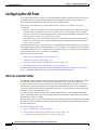
In Figure 7-1, a port group of two workstations communicates with a router. Because the router is a
single-MAC-address device, source-based forwarding ensures that the switch uses all available
bandwidth to the router. The router is configured for destination-based forwarding because the large
number of stations ensures that the traffic is evenly distributed through the port-group ports on the router.
Figure 7-1
Source-Based Forwarding
Source-based
forwarding
Destination-based
forwarding
Catalyst 2900 XL
or Catalyst 3500 XL switch
Cisco router
12650
FEC port group
The switch treats the port group as a single logical port; therefore, when you create a port group, the
switch uses the configuration of the first port for all ports added to the group. If you add a port and
change the forwarding method, it changes the forwarding for all ports in the group. After the group is
created, changing STP or VLAN membership parameters for one port in the group automatically
changes the parameters for all ports. Each port group has one port that carries all unknown multicast,
broadcast, and STP packets.
Port Group Restrictions on Static-Address Forwarding
These restrictions apply to entering static addresses that are forwarded to port groups:
•
If the port group forwards based on the source MAC address (the default), configure the static
address to forward to all ports in the group. This method eliminates the chance of lost packets.
•
If the port group forwards based on the destination address, configure the static address to forward
to only one port in the port group. This method avoids the possible transmission of duplicate
packets. For more information, see the “Adding Static Addresses” section on page 6-19.
Catalyst 2900 Series XL and Catalyst 3500 Series XL Software Configuration Guide
7-8
78-6511-08
Chapter 7
Configuring the Switch Ports
Configuring Protected Ports
Creating EtherChannel Port Groups
Beginning in privileged EXEC mode, follow these steps to create a two-port group:
Command
Purpose
Step 1
configure terminal
Enter global configuration mode.
Step 2
interface interface
Enter interface configuration mode, and enter the port of the first port to be
added to the group.
Step 3
port group 1 distribution
destination
Assign the port to group 1 with destination-based forwarding.
Step 4
interface interface
Enter the second port to be added to the group.
Step 5
port group 1 distribution
destination
Assign the port to group 1 with destination-based forwarding.
Step 6
end
Return to privileged EXEC mode.
Step 7
show running-config
Verify your entries.
Configuring Protected Ports
Some applications require that no traffic be forwarded by the Layer 2 protocol between ports on the same
switch. In such an environment, there is no exchange of unicast, broadcast, or multicast traffic between
ports on the switch, and traffic between ports on the same switch is forwarded through a Layer 3 device
such as a router.
To meet this requirement, you can configure Catalyst 2900 XL and Catalyst 3500 XL ports as protected
ports (also referred to as private VLAN edge ports). Protected ports do not forward any traffic to
protected ports on the same switch. This means that all traffic passing between protected ports—unicast,
broadcast, and multicast—must be forwarded through a Layer 3 device. Protected ports can forward any
type of traffic to unprotected ports, and they forward as usual to all ports on other switches.
Note
Sometimes unknown unicast traffic from an unprotected port is flooded to a protected port because a
MAC address has timed out or has not been learned by the switch. Use the port block command to
guarantee that in such a case no unicast and multicast traffic is flooded to the port. See the “Configuring
Flooding Controls” section on page 7-4 for more information.
Beginning in privileged EXEC mode, follow these steps to define a port as a protected port:
Command
Purpose
Step 1
configure terminal
Enter global configuration mode.
Step 2
interface interface
Enter interface configuration mode, and enter the port to be configured.
Step 3
port protected
Enable protected port on the port.
Step 4
end
Return to privileged EXEC mode.
Step 5
show port protected
Verify that the protected port option is enabled.
Use the no version of the port protected interface configuration command to disable the protected port
option.
Catalyst 2900 Series XL and Catalyst 3500 Series XL Software Configuration Guide
78-6511-08
7-9
Chapter 7
Configuring the Switch Ports
Enabling Port Security
Enabling Port Security
Secured ports restrict a port to a user-defined group of stations. When you assign secure addresses to a
secure port, the switch does not forward any packets with source addresses outside the group of
addresses you have defined. If you define the address table of a secure port to contain only one address,
the workstation or server attached to that port is guaranteed the full bandwidth of the port. As part of
securing the port, you can also define the size of the address table for the port.
Secured ports generate address-security violations under these conditions:
•
The address table of a secured port is full and the address of an incoming packet is not found in the
table.
•
An incoming packet has a source address assigned as a secure address on another port.
Limiting the number of devices that can connect to a secure port has these advantages:
•
Dedicated bandwidth—If the size of the address table is set to 1, the attached device is guaranteed
the full bandwidth of the port.
•
Added security—Unknown devices cannot connect to the port.
These options validate port security or indicate security violations:
Interface
Port to secure.
Security
Enable port security on the port.
Trap
Issue a trap when an address-security violation occurs.
Shutdown Port
Disable the port when an address-security violation occurs.
Secure Addresses
Number of addresses in the address table for this port. Secure ports have at
least one address.
Max Addresses
Number of addresses that the address table for the port can contain.
Security Rejects
The number of unauthorized addresses seen on the port.
For the restrictions that apply to secure ports, see the “Avoiding Configuration Conflicts” section on
page 9-7.
Defining the Maximum Secure Address Count
A secure port can have from 1 to 132 associated secure addresses. Setting one address in the MAC
address table for the port ensures that the attached device has the full bandwidth of the port.
Enabling Port Security
Beginning in privileged EXEC mode, follow these steps to enable port security:
Command
Purpose
Step 1
configure terminal
Enter global configuration mode.
Step 2
interface interface
Enter interface configuration mode for the port you want to secure.
Catalyst 2900 Series XL and Catalyst 3500 Series XL Software Configuration Guide
7-10
78-6511-08
Chapter 7
Configuring the Switch Ports
Enabling Port Security
Command
Purpose
Step 3
port security max-mac-count 1
Secure the port and set the address table to one address.
Step 4
port security action shutdown
Set the port to shutdown when a security violation occurs.
Step 5
end
Return to privileged EXEC mode.
Step 6
show port security
Verify the entry.
Disabling Port Security
Beginning in privileged EXEC mode, follow these steps to disable port security:
Command
Purpose
Step 1
configure terminal
Enter global configuration mode.
Step 2
interface interface
Enter interface configuration mode for the port you want to disable port
security.
Step 3
no port security
Disable port security.
Step 4
end
Return to privileged EXEC mode.
Step 5
show port security
Verify the entry.
Configuring Port Security Aging
Note
This feature is not available on the Catalyst 2900 LRE XL switches.
You can use port security aging to set the aging time for all dynamic and static secure addresses on a
port. When port security aging is enabled on a port, the secure addresses on the port are deleted only if
the secure addresses are inactive for the specified aging time.
Use this feature to remove and add PCs on a secure port without manually deleting the existing secure
MAC addresses and to still limit the number of secure addresses on a port.
Beginning in privileged EXEC mode, follow these steps to enable the port security aging feature:
Command
Purpose
Step 1
configure terminal
Enter global configuration mode.
Step 2
interface interface
Enter interface configuration mode for the port on which you want to enable
port security aging.
Step 3
port security aging time time
Enable port security aging for this port and set the aging time. For time,
specify the age time for this port. Valid range is from 0 to 1440 minutes. If the
time is equal to 0, aging is disabled for this port.
Step 4
end
Return to privileged EXEC mode.
Step 5
show port security [interface-id]
Verify the entry.
Catalyst 2900 Series XL and Catalyst 3500 Series XL Software Configuration Guide
78-6511-08
7-11
Chapter 7
Configuring the Switch Ports
Configuring SPAN
To disable port security aging for all secure addresses on a port, use the no port security aging time
interface configuration command.
This example shows how to set the port security aging time to 2 hours on port 1.
Switch(config)#interface fa0/1
Switch(config-if)#port security aging time 120
Configuring SPAN
You can use Switch Port Analyzer (SPAN) to monitor traffic on a given port by forwarding incoming and
outgoing traffic on the port to another port in the same VLAN. A SPAN port cannot monitor ports in a
different VLAN, and a SPAN port must be a static-access port. You can define any number of ports as
SPAN ports, and any combination of ports can be monitored.
For the restrictions that apply to SPAN ports, see the “Avoiding Configuration Conflicts” section on
page 9-7.
Enabling SPAN
Beginning in privileged EXEC mode, follow these steps to enable SPAN:
Command
Purpose
Step 1
configure terminal
Enter global configuration mode.
Step 2
interface interface
Enter interface configuration mode, and enter the port that acts as the
monitor port.
Step 3
port monitor interface
Enable port monitoring on the port.
Step 4
end
Return to privileged EXEC mode.
Step 5
show running-config
Verify your entries.
Disabling SPAN
Beginning in privileged EXEC mode, follow these steps to disable SPAN:
Command
Purpose
Step 1
configure terminal
Enter global configuration mode.
Step 2
interface interface
Enter interface configuration mode, and enter the port number of the monitor
port.
Step 3
no port monitor interface
Disable port monitoring on the port.
Step 4
end
Return to privileged EXEC mode.
Step 5
show running-config
Verify your entries.
Catalyst 2900 Series XL and Catalyst 3500 Series XL Software Configuration Guide
7-12
78-6511-08
Chapter 7
Configuring the Switch Ports
Configuring Voice Ports
Configuring Voice Ports
The Catalyst 2900 XL and Catalyst 3500 XL switches can connect to Cisco IP Phonesand carry IP voice
traffic. If necessary, the Catalyst 3524-PWR XL can supply electrical power to the circuit connecting it
to the phone. For information about Catalyst 3524-PWR XL inline power, see the “Configuring Inline
Power on the Catalyst 3524-PWR Ports” section on page 7-15.
Because the sound quality of an IP telephone call can deteriorate if the data is unevenly sent, the switch
uses quality of service (QoS) based on IEEE 802.1p class of service (CoS). QoS uses classification and
scheduling to send network traffic from the switch in a predictable manner. The Cisco IP Phone or access
point itself is also a configurable device, and you can configure it to forward traffic with an 802.1p
priority. You can use the CLI to configure the Catalyst 3524-PWR XL to honor or ignore a traffic priority
assigned by a Cisco IP Phone or access point.
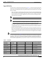
For example, the Cisco 7960 IP Phone contains an integrated three-port 10/100 switch. The ports are
dedicated connections to these devices:
•
Port 1 connects to the Catalyst 3524-PWR XL switch or other voice-over-IP device.
•
Port 2 is an internal 10/100 interface that carries the phone traffic.
•
Port 3 connects to a PC or other device.
Figure 7-2 shows one way to configure a Cisco 7960 IP Phone.
Figure 7-2
Cisco 7960 IP Phone Connected to a Catalyst 3524-PWR XL Switch
Catalyst
3524-PWR XL
Cisco 7960 IP Phone
PC
33048
IP
802.1Q trunk
Preparing a Port for a Cisco IP Phone Connection
Before you configure a Catalyst 3524-PWR XL port to carry IP voice traffic, configure the port as an
802.1Q trunk and as a member of the voice VLAN (VVID). See the “Configuring a Trunk Port” section
on page 8-28 for instructions.
Catalyst 2900 Series XL and Catalyst 3500 Series XL Software Configuration Guide
78-6511-08
7-13
Chapter 7
Configuring the Switch Ports
Configuring Voice Ports
Configuring a Port to Connect to a Cisco IP Phone
Because a Cisco IP Phone also supports connection to a PC or other device, a port connecting a
Catalyst 3524-PWR XL switch to a Cisco IP Phone can carry mixed traffic. There are three
configurations for a port connected to a Cisco IP Phone:
•
All traffic is sent according to the default COS priority of the port. This is the default.
•
Voice traffic is given a higher priority by the phone, and all traffic is in the same VLAN.
•
Voice and data traffic are carried on separate VLANs, and voice traffic always has a CoS priority
of 5.
Beginning in privileged EXEC mode, follow these steps to configure a port to instruct the phone to give
voice traffic a higher priority and to forward all traffic through the 802.1Q native VLAN:
Command
Purpose
Step 1
configure terminal
Enter global configuration mode.
Step 2
interface interface
Enter interface configuration mode, and enter the port to be configured.
Step 3
switchport voice vlan dot1p
Instruct the switch port to use 802.1p priority tagging for voice traffic and to
use VLAN 0 (default native VLAN) to carry all traffic.
Step 4
end
Return to privileged EXEC mode.
Step 5
show interface interface switchport
Verify the port configuration.
Overriding the CoS Priority of Incoming Frames
A PC or other data device can connect to a Cisco IP Phone port. The PC can generate packets with an
assigned CoS value. If you want, you can use the Catalyst 3524-PWR XL CLI to override the priority of
frames arriving on the phone port from connected devices. You can also set the phone port to accept
(trust) the priority of frames arriving on the port.
Beginning in privileged EXEC mode, follow these steps to override the CoS priority setting received
from the nonvoice port on the Cisco IP Phone:
Command
Purpose
Step 1
configure terminal
Enter global configuration mode.
Step 2
interface interface
Enter interface configuration mode, and enter the switch port to be
configured.
Step 3
switchport priority extend
cos 3
Set the phone port to override the priority received from the PC or the
attached device and forward the received data with a priority of 3.
Step 4
end
Return to privileged EXEC mode.
Step 5
show interface interface switchport
Verify the change.
Use the no switchport priority extend command to return the port to its default setting.
Catalyst 2900 Series XL and Catalyst 3500 Series XL Software Configuration Guide
7-14
78-6511-08
Chapter 7
Configuring the Switch Ports
Configuring Inline Power on the Catalyst 3524-PWR Ports
Configuring Voice Ports to Carry Voice and Data Traffic on Different VLANs
The Cisco 7960 IP Phone has an integrated three-port 10/100 switch that can connect to a PC or other
device. You can configure a switch port to instruct the phone to forward voice and data traffic on different
virtual LANs (VLANs).
In this configuration, VLAN 1 carries data traffic, and VLAN 2 carries voice traffic. In this
configuration, you must connect all Cisco IP Phones and other voice-related devices to switch ports that
belong to VLAN 2.
Beginning in privileged EXEC mode, follow these steps to configure a port to receive voice and data
from a Cisco IP Phone in different VLANs:
Command
Purpose
Step 1
configure terminal
Enter global configuration mode.
Step 2
interface interface
Enter interface configuration mode, and enter the port to be configured.
Step 3
switchport priority default (0)
Assign an IEEE 802.1p priority to untagged traffic that is received on the
switch port. The Cisco IP Phone forwards this traffic through the native
VLAN, VLAN 1.
Step 4
switchport voice vlan (2)
Instruct the Cisco IP Phone to forward all voice traffic through VLAN 2. The
Cisco IP Phone forwards the traffic with an 802.1p priority of 5.
Step 5
end
Return to privileged EXEC mode.
Step 6
show interface interface switchport
Verify the configuration.
Configuring Inline Power on the Catalyst 3524-PWR Ports
The Catalyst 3524-PWR XL switch automatically supplies inline power to connected Cisco IP Phones
and Cisco access points if it senses no power on the circuit. If there is power on the circuit, the switch
does not supply it. You can also configure the Catalyst 3524-PWR XL switch to never supply power to
these devices and to disable the inline-power detection mechanism.
Cisco IP Phones and access points can also be connected to an AC power source and supply their own
power to the voice circuit.
For information about configuring a switch port to forward IP voice traffic to and from connected
Cisco IP Phones, see the “Configuring Voice Ports to Carry Voice and Data Traffic on Different VLANs”
section on page 7-15.
Beginning in privileged EXEC mode, follow these steps to disable the inline-power detection mechanism
on a switch port:
Command
Purpose
Step 1
configure terminal
Enter global configuration mode.
Step 2
interface interface
Enter interface configuration mode, and enter the port to be configured.
Step 3
power inline never
Permanently disable inline power on the port.
Step 4
end
Return to privileged EXEC mode.
Step 5
show power inline interface
configured
Verify the change.
To enable inline-power detection mechanism on a switch port, use the power inline auto interface
configuration command.
Catalyst 2900 Series XL and Catalyst 3500 Series XL Software Configuration Guide
78-6511-08
7-15
Chapter 7
Configuring the Switch Ports
Configuring the LRE Ports
Configuring the LRE Ports
The Catalyst 2900 LRE XL switches use Long-Reach Ethernet (LRE) technology to transfer data, voice,
and video traffic over categorized and noncategorized unshielded twisted-pair cable (Category 1, 2,
and 3 structured and unstructured cable such as existing telephone lines).
Connecting a switch LRE port to a remote Ethernet device (such as a PC) requires two types of
connections:
•
LRE link—This is the connection between the switch LRE port and the RJ-11 wall port on an LRE
customer premises equipment (CPE) device such as the Cisco 575 LRE CPE or Cisco 585 LRE
CPE. This connection can be through categorized or noncategorized unshielded twisted-pair cable
and can extend to distances of up to 4921 feet (1500 m).
•
CPE Ethernet link—This is the connection between the CPE Ethernet port and an Ethernet device,
such as a PC. This connection is through standard Category 5 cabling and can extend to distances
of up to 328 feet (100 m).
The actual line speed in either direction between a switch LRE port and remote Ethernet device depends
on the LRE link speed and the CPE Ethernet link speed. For example, if a PC Ethernet port is configured
to 100 Mbps and the LRE port is configured with an upstream link speed of 5.69 Mbps, the actual upload
rate provided to the PC user is 5.69 Mbps, not 100 Mbps.
This section discusses these topics:
•
“LRE Links and LRE Profiles” section on page 7-16
•
“CPE Ethernet Links” section on page 7-21
•
“Assigning a Public Profile to All LRE Ports” section on page 7-22
•
“Assigning a Private Profile to an LRE Port” section on page 7-23
For LRE troubleshooting information, see the “Troubleshooting LRE Port Configuration” section on
page 9-9. Additional LRE details are provided in the switch command reference.
LRE Links and LRE Profiles
The LRE link settings define the connection between the switch LRE port and the CPE RJ-11 wall port.
The LRE link provides symmetric and asymmetric bandwidth for data, voice, and video traffic.
Symmetric transmission is when the downstream and upstream bandwidths are the same. Asymmetric
transmission is when the downstream and the upstream bandwidths differ. Downstream transmission
refers to the traffic traveling from the LRE switch to the CPE. Upstream transmission refers to the traffic
traveling from the CPE to the LRE switch.
The switch controls upstream and downstream rates on the LRE link by using configurations called
profiles. Depending on the profile, the upstream and downstream bands on an LRE link can range from
approximately 1 Mbps to 15 Mbps.
You can assign profiles on a per-port or switch-wide basis. When the LRE switch establishes a link with
the CPE, the switch downloads its profile settings to the CPE so that the switch and CPE operate with
the same configuration.
This section discusses these topics:
•
“Types of LRE Profiles” section on page 7-17
•
“Environmental Considerations for LRE Links” section on page 7-18
•
“Considerations for Using LRE Profiles” section on page 7-19
Catalyst 2900 Series XL and Catalyst 3500 Series XL Software Configuration Guide
7-16
78-6511-08
Chapter 7
Configuring the Switch Ports
Configuring the LRE Ports
Types of LRE Profiles
The LRE switches are shipped with predefined profiles (Table 7-1) categorized as public (global) mode
and private (per-port) mode profiles. By default, all LRE ports on the switch are enabled with the LRE-10
private profile. This default profile allows the upstream and downstream transmission rate on the LRE
link to be 10 Mbps.
•
Public—We strongly recommend using a public profile if the switch is used with equipment directly
connected to a Public Switched Telephone Network (PSTN) without a private branch exchange (PBX)
between the LRE switch and the public telephone lines. When the switch is configured with a public
profile, all LRE ports use the same configuration to prevent the switch from causing interference
with the other lines on the PSTN.
Note
Consult the regulations for connecting to the PSTN in your area.
Note
Cisco LRE products can share lines with analog telephones, Integrated Services Digital Network
(ISDN), and digital PBX switch telephones that use the 0 to 700 kHz frequency range.
The standards for spectral profiles have not yet been ratified. The PUBLIC-ANSI profile
corresponds to ANSI Plan 998. The PUBLIC-ETSI profile corresponds to ETSI Plan 997. Both plans
are draft standards. Contact Cisco Systems for the latest information about standards ratification or
for updates to the public profiles.
•
Note
Table 7-1
Private—You can use a private profile if the LRE switch is not used with equipment connected to a
PSTN. The switch supports a variety of private profiles that offer different link speeds and maximum
distances. In general, the higher the link speed, the shorter the maximum distance. Private profiles
are assigned on a per-port basis. The ports on an LRE switch can be assigned the same or different
private profiles.
Use the rates and distances in Table 7-1 as guidelines only. Factors such as the type of cable that you
use, how it is bundled, and the interference and noise on the LRE link can affect the actual LRE link
performance. Contact Cisco Systems for information about limitations and optimization of LRE link
performance. The net data rates in the table are slightly less than the gross data rates displayed by the
show controllers lre profile names privileged EXEC command. The actual bandwidth is somewhat less.
LRE Profiles
Profile Name
Profile Type
LRE Link
Downstream Rate (Mbps)
LRE Link
Maximum Distance between
Upstream Rate (Mbps) the LRE Switch and LRE CPE
PUBLIC-ANSI
Public
15.17
4.27
4101 ft (1250 m)
PUBLIC-ETSI
Public
11.38
4.27
4101 ft (1250 m)
LRE-5
Private
5.69
5.69
4921 ft (1500 m)
LRE-10 (default)
Private
11.38
11.38
4101 ft (1250 m)
LRE-15
Private
15.17
17.06
3445 ft (1050 m)
LRE-10-1
Private
11.38
1.43
4101 ft (1250 m)
LRE-10-3
Private
11.38
2.87
4101 ft (1250 m)
LRE-10-5
Private
11.38
5.69
4101 ft (1250 m)
Catalyst 2900 Series XL and Catalyst 3500 Series XL Software Configuration Guide
78-6511-08
7-17
Chapter 7
Configuring the Switch Ports
Configuring the LRE Ports
Table 7-1
LRE Profiles (continued)
Profile Name
Profile Type
LRE Link
Downstream Rate (Mbps)
LRE Link
Maximum Distance between
Upstream Rate (Mbps) the LRE Switch and LRE CPE
LRE-5LL
Private
5.69
5.69
4921 ft (1500 m)
LRE-10LL
Private
11.38
11.38
4101 ft (1250 m)
LRE-15LL
Private
15.17
17.06
3445 ft (1050 m)
Environmental Considerations for LRE Links
The requirements of your LRE environment are based on these factors:
•
Maximum distance between the LRE switch and CPEs—LRE runs on Category 1, 2, and 3
structured and unstructured cable. The maximum distance supported on the LRE link is from 3500
to 5000 feet, depending on the profile. The higher the profile, the shorter the distance. In buildings
where LRE traffic runs over bundled telco cabling, the maximum distance supported can be
approximately 30 percent lower.
Each terminated bridge tap in a room can further reduce LRE link distances by 300 feet. The quality
of the cable, the size of the cable bundles, and cross talk within the bundle also can affect overall
reach.
•
Site type—If your site has either a PBX providing telephone service throughout or has direct
connections to the PSTN, you must identify the requirements of your local public telephone service
provider.
If your site is a single building (or is a connected set of buildings), consult a qualified electrician to
ensure that the wiring conforms to the appropriate regulations for indoor circuits.
If your site has separate buildings, you must determine how the buildings are cabled to each other.
Where the wiring between the LRE switch and CPE leaves the building (or the armored conduits
certified for inside wiring standards), it must be protected against lightning and shorts to
high-voltage power. This protection might be provided by fuses or overvoltage protectors that
comply with local regulations for outside wiring protection. Consult an expert in local
telecommunications regulations for the details of this protection.
•
Age and type of wiring—You can estimate the type of wiring you have based on your site’s age and
type.
– Newer installations less than 15 years old often use Category 3 cable in bundles of 25 pairs.
There is no significant difference between 25-pair bundles and larger bundles.
– Older installations (hotel, school, hospital, commercial—North America) 15 to 30 years old
often use 24 AWG wiring with between 1 and 12 twists per foot (similar to Category 1) in
bundles of 25 or more.
– Older installations (residential—North America) 15 to 30 years old often use 26 AWG wiring
with between 1 and 12 twists per foot (maybe type-2) in bundles of 100 or more.
– Older installations (Europe) 15 to 30 years old often use 0.4 mm (similar to 26 AWG) wiring
with between 1 and 12 twists per foot in bundles of 100 or more.
Catalyst 2900 Series XL and Catalyst 3500 Series XL Software Configuration Guide
7-18
78-6511-08
Chapter 7
Configuring the Switch Ports
Configuring the LRE Ports
– Older installations (Asia) 15 to 30 years old often use 0.4 mm (similar to 26 AWG) wiring with
between 1 and 12 twists per foot in bundles of 100 or more.
– Older installations over 30 years old often use heavy gauge wire (22 or 20 AWG) with no
significant twist. In many cases, the cabling is set into the fabric of the building. The cables
might be tightly or loosely bundled. For this estimate, assume that they are tightly bundled in
groups of 25 or more.
•
Cross talk (noise) and interference—LRE operates with any number of wires in a cable binder
carrying the LRE signal. Anywhere from one wire pair to every wire pair in the cable can carry LRE
signals at the same time. LRE operates in full cable binders and adjusts power levels on each LRE
link to maximize the performance of all connections.
The greatest impact on LRE performance is from the frequency response of the cable at the higher
frequencies. LRE signals are more susceptible to interference at higher frequencies. The LRE
upstream signal operates at the high end of the frequency spectrum. Cables have higher attenuation
at higher frequencies and also interfere with other pairs in the bundle at higher frequencies. This
interference or cross talk can significantly impact the signal quality.
Considerations for Using LRE Profiles
When assigning a profile to a switch LRE port, keep these considerations in mind:
•
Each switch LRE port always has a private profile assigned to it. The LRE-10 profile is the default.
Public profiles have priority over private profiles. If you assign a public profile to the switch, the
switch uses the public profile and ignores any private profile assigned to the switch LRE ports.
If a public profile is configured on the switch and you want the switch LRE ports to use private
profiles, you must first disable the public profile by using the no lre profile global global
configuration command.
When you assign a different profile to a switch LRE port, the port immediately resets and uses the
newly assigned profile.
•
Before you add an LRE switch to a cluster, make sure that you assign it the same public profile that
is used by other LRE switches in the cluster. A configuration conflict occurs if a switch cluster has
LRE switches using both private and public profiles. If one LRE switch in a cluster is assigned a
public profile, all LRE switches in that cluster must have that same public profile.
A cluster can have a mix of LRE switches using different private profiles. For more information
about clusters, see Chapter 5, “Clustering Switches.”
•
Phone lines typically operate at a frequency of up to 3.4 kHz. On the LRE link, the downstream
transmission runs in a low-frequency band from approximately 1 MHz to 3.5 MHz. The upstream
transmission runs in a high-frequency band from approximately 4 MHz to 8 MHz. Higher
frequencies are more susceptible to interference. Consequently, upstream signals are susceptible to
cross talk and disruption on the link.
To maintain the quality of the LRE connection, use the asymmetric private profiles. These profiles
use a low upstream rate but provide a high downstream rate. We recommend configuring all switch
LRE ports with the LRE-10-5 profile rather than the default LRE-10 profile.
•
Use the LL profiles (LRE-5LL, LRE-10LL, and LRE-15LL) with care. These profiles have the
low-latency (LL) feature enabled and the interleaver feature turned off. The LL feature does not
delay data transmission, but it makes data more susceptible to interruptions on the LRE link.
All other profiles, public and private, have the interleaver feature enabled and the LL feature
disabled. The interleaver feature provides maximum protection against small interruptions on the
LRE link but delays data transmission.
Catalyst 2900 Series XL and Catalyst 3500 Series XL Software Configuration Guide
78-6511-08
7-19
Chapter 7
Configuring the Switch Ports
Configuring the LRE Ports
•
We recommend using one of these six private profiles (LRE-5, LRE-10, LRE-15, LRE-10-1,
LRE-10-3, and LRE-10-5) when the link between the LRE switch and the CPE does not need to
coexist in the same cable bundle as Asymmetric Digital Subscriber Line (ADSL) signaling.
For these profiles, the LRE downstream channel operates between 900 kHz and 3.5 MHz and
between 4 MHz and 8 MHz.
•
The symmetric profiles (LRE-5, LRE-10, LRE-15) provide full-duplex throughput on the link
between the LRE switch and CPE. Under ideal conditions, this can mean up to 30 Mbps of
bandwidth on the LRE link if you are using the LRE-15 profile.
Note
Avoid using the symmetric profiles when the LRE switch and CPE link need to coexist in the
same cable bundle with ADSL signaling. Cross talk and interference across wire pairs in cable
bundles can degrade Ethernet performance.
Note
All POTS telephones not directly connected to the CPE require microfilters with a 300-ohm
termination. Microfilters improve voice call quality when voice and data equipment are using
the same telephone line. They also prevent nonfiltered telephone rings and nonfiltered telephone
transitions (such as on-hook to off-hook) from interrupting the LRE connection.
•
We recommend using the ANSI and ETSI asymmetric public profiles for North America and other
countries, respectively, when LRE signaling needs to coexist with ADSL signaling. We also
recommend using a public profile when the PBX is not on-site and the POTS splitter directly
connects to the PSTN. This guarantees that the LRE upstream frequency band cuts off at 5.2 MHz
allowing the LRE upstream signal to be spectrally compatible with ADSL in the same cable bundle.
Note
LRE signaling can coexist with ADSL signaling in the same cable bundle. However, LRE
signaling is not compatible with T1 signals in the same cable bundle.
•
The LRE link must have a minimum signal-to-noise ratio (SNR) to operate. Link is not established
if the SNR is insufficient. Each profile requires a different minimum SNR ratio (Table 7-2).
Table 7-2
Minimum SNR Ratios
Profile
Minimum SNR
Public-ANSI
Local 19 db, remote 25 db
Public-ETSI
Local 19 db, remote 25 db
LRE-5 and LRE-5LL
Local 13 db, remote 19 db
LRE-10, LRE-10-1, LRE-10-3, LRE-10-5, and LRE-10LL
Local 19 db, remote 25 db
LRE-15 and LRE-15LL
Local 25 db, remote 31 db
Use the show controllers lre privileged EXEC commands to display the LRE link statistics and profile
information on the LRE ports. For information about these commands, refer to the switch command
reference.
Catalyst 2900 Series XL and Catalyst 3500 Series XL Software Configuration Guide
7-20
78-6511-08
Chapter 7
Configuring the Switch Ports
Configuring the LRE Ports
CPE Ethernet Links
The CPE Ethernet link settings define the connection between the CPE Ethernet port and a remote
Ethernet device, such as a PC.
Note
From CMS and the CLI, you can configure and monitor the Ethernet link on a Cisco 575 LRE CPE. You
cannot configure the Ethernet links on a Cisco 585 LRE CPE. You can only monitor the Ethernet links
on the Cisco 585 LRE CPE by using the show remote interfaces status user EXEC command. For
information about the switch LEDs, see Table 2-8 on page 2-10 and the Catalyst 2900 Series XL
Hardware Installation Guide.
Keep these considerations in mind when you have CPEs connected to the LRE ports:
•
Enable CDP either globally on the LRE switch or on the specific LRE ports.
•
Use the lre shutdown interface configuration command to disable the LRE interface transmitter
on any LRE ports that are not connected to a CPE. This prevents access to the LRE port and prevents
the power emitted from the port from affecting other ports.
•
You cannot configure the flow-control setting on the LRE ports. The flow-control setting on the CPE
Ethernet port is automatically disabled in half-duplex mode and is automatically enabled in
full-duplex mode.
•
You can connect Cisco 575 LRE CPEs and Cisco 585 LRE CPEs to the same LRE switch,.
•
You can hot-swap the CPEs without powering down the switch or disrupting the other switch ports.
Use the show controllers ethernet-controller privileged EXEC command to display the internal switch
statistics, the statistics collected by the LRE switch interface, and the statistics collected by the CPE LRE
interface. For information about this command, refer to the switch command reference.
Considerations for Connected Cisco 575 LRE CPEs
You can configure the Cisco 575 LRE CPE Ethernet port to operate at 10 or 100 Mbps and at half- or
full-duplex mode, depending on the capability of the remote Ethernet device. Autonegotiation for port
speed and duplex mode is supported.
The default speed for the CPE Ethernet port is auto. The default duplex mode is half duplex with back
pressure.
The speeds on the LRE links and CPE Ethernet links do not need to match. However, to prevent the
possible loss of data when the LRE link is slower than the CPE Ethernet link, make sure that the CPE
Ethernet port is set to half-duplex mode. Use duplex autonegotiation only if the remote device supports
802.1X full-duplex flow control. The PC user should notice no significant difference in performance
between 100-Mbps half duplex and 100-Mbps full duplex. Use the duplex and speed interface
configuration commands, respectively, to change the duplex and speed settings on the Cisco 575 LRE
CPE Ethernet port.
Catalyst 2900 Series XL and Catalyst 3500 Series XL Software Configuration Guide
78-6511-08
7-21
Chapter 7
Configuring the Switch Ports
Configuring the LRE Ports
Considerations for Connected Cisco 585 LRE CPEs
You cannot configure the Cisco 585 LRE CPE Ethernet ports.
The default speed for the CPE Ethernet ports is auto. The default duplex mode is half duplex with back
pressure. Duplex autonegotiation is not supported on the Cisco 585 LRE CPE.
You cannot enable or disable the CPE Ethernet ports on a per-port basis. For example, using the
shutdown interface configuration command on an LRE port disables all Ethernet ports on the connected
CPE.
The loopback interface configuration command is not supported on the LRE ports. External loopback
on the LRE ports is also not supported. Connecting a CPE Ethernet port to another Ethernet port on the
same CPE can create a loop. If this happens, the switch stops sending to the CPE and blocks Ethernet
traffic coming from the CPE.
Assigning a Public Profile to All LRE Ports
Public profiles are set on a switch-wide (global) basis. The public profile you select should be compatible
with the PSTN to which the LRE switch is connected.
Public profiles have priority over private profiles. If you assign a public profile to the switch, the switch
ignores the private profile settings and uses the public profile settings on all LRE ports. To disable the
public profile on the switch, use the no lre profile global global configuration command.
Changes to the public profile settings are immediately put in effect, and the public mode automatically
becomes the active mode.
Beginning in privileged EXEC mode, follow these steps to assign a public profile to the LRE ports:
Command
Purpose
Step 1
configure terminal
Enter global configuration mode.
Step 2
lre profile global profile_name
Enter the public profile name: PUBLIC-ANSI or PUBLIC-ETSI.
Step 3
end
Return to privileged EXEC mode.
Step 4
show controllers lre profile
mapping
Verify the change.
Use the show controllers lre privileged EXEC commands to display the LRE link statistics and profile
information on the LRE ports. For information about these commands, refer to the switch command
reference.
Catalyst 2900 Series XL and Catalyst 3500 Series XL Software Configuration Guide
7-22
78-6511-08
Chapter 7
Configuring the Switch Ports
Configuring the LRE Ports
Assigning a Private Profile to an LRE Port
Private profiles are set on a per-port basis. You can assign the same private profile or different private
profiles to the LRE ports on the switch. The default active private profile on all LRE ports is LRE-10.
The switch resets the ports with the updated profile settings.
Beginning in privileged EXEC mode, follow these steps to assign a private profile to an LRE port:
Command
Purpose
Step 1
configure terminal
Enter global configuration mode.
Step 2
interface LRE-interface
Enter interface configuration mode, and enter the number of the LRE port to
be configured.
Step 3
lre profile profile_name
Enter the private profile name: LRE-5, LRE-10 (default), LRE-15,
LRE-10-1, LRE-10-3, LRE-10-5, LRE-5LL, LRE-10LL, and LRE-15LL.
The default profile is LRE-10.
Step 4
end
Return to privileged EXEC mode.
Step 5
show controllers lre profile
mapping
Verify the change.
Use the show controllers lre privileged EXEC commands to display the LRE link statistics and profile
information on the LRE ports. For information about these commands, refer to the switch command
reference.
Catalyst 2900 Series XL and Catalyst 3500 Series XL Software Configuration Guide
78-6511-08
7-23
Chapter 7
Configuring the Switch Ports
Configuring the LRE Ports
Catalyst 2900 Series XL and Catalyst 3500 Series XL Software Configuration Guide
7-24
78-6511-08