1
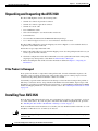
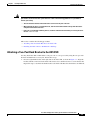
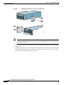
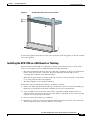
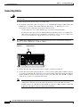
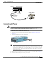
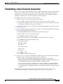
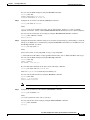
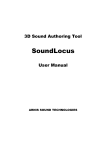
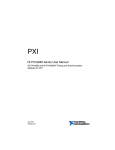
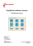
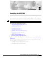
C H A P T E R
3
Installing the AVS 3120
This chapter explains how to install the AVS 3120 in an equipment rack, or on a table or workbench.
This chapter also provides instructions for connecting cables, AC power, and for booting the AVS 3120.
Warning
Read the installation instructions before connecting the system to the power source. Statement 1004
This chapter contains the following major sections:
•
Unpacking and Inspecting the AVS 3120, page 3-2
•
Installing Your AVS 3120, page 3-2
•
Connecting Cables, page 3-6
•
Connecting AC Power, page 3-7
•
Booting the AVS 3120, page 3-8
•
Establishing a Serial Console Connection, page 3-9
•
Configuring Network Settings, page 3-10
•
Setting the Time, page 3-12
•
Checking the Front Panel LEDs, page 3-13
•
Removing or Replacing an AVS 3120, page 3-14
Before you begin the installation, be sure you have read the Regulatory Compliance and Safety
Information for the Cisco AVS 3120 Application Velocity System document and Chapter 2, “Preparing
for Installation.”
Also, you may want to familiarize yourself with the AVS software by reading the following related
documents, which you can obtain from Cisco.com:
•
Release Note for the Cisco Application Velocity System
•
Cisco Application Velocity System User Guide
Cisco AVS 3120 Application Velocity System Hardware Installation Guide
OL-11805-01
3-1
Chapter 3
Installing the AVS 3120
Unpacking and Inspecting the AVS 3120
Unpacking and Inspecting the AVS 3120
The AVS 3120 shipment contains the following items:
•
One RJ-45 to female 25-pin sub-d connector
•
One RJ-45 to female 9-pin sub-d connector
•
One RJ-45 console cable
•
Two 6-ft Ethernet cables
•
One rack mounting kit—two metal brackets and screws
•
Four rubber feet
•
Cisco Product Documentation CD-ROM and Warranty Package
•
Cisco AVS 3120 Application Velocity System Hardware Installation Guide
The AVS 3120 is shipped in a protective shipping carton. It is shipped as a self-contained chassis; no
components can be added or removed.
Follow these steps to unpack the AVS 3120:
1.
Remove the AVS 3120 accessories from the shipping carton. Save the packing materials in case you
need to repack the AVS 3120 later.
2.
Check the configuration of the AVS 3120 and the accessories against the items listed on the packing
slip. Report any discrepancies as described in “If the Product is Damaged”.
3.
Before installing the AVS 3120, review the information outlined in Chapter 2, “Preparing for
Installation.”
If the Product is Damaged
If any portion of the unit or component is damaged in transit, forward an immediate request to the
delivering carrier to perform an inspection of the product and to prepare a damage report. Save the
container and all packing materials until the contents are verified.
Concurrently, report the nature and extent of the damage to Customer Service. Report the problem or
deficiency to Customer Service along with the model number and serial number. Upon receipt of this
information, you will be provided with service instructions, or a Return Material Authorization (RMA)
number and shipping information. To obtain assistance, refer to the “Obtaining Documentation” section
on page xiv.
Installing Your AVS 3120
Place the AVS 3120 in the desired location. You can mount it in a rack for your convenience, or place it
on a solid, stable surface. If you do not plan to install the AVS 3120 in an equipment rack, proceed to
the “Installing the AVS 3120 on a Workbench or Tabletop” section on page 3-5.
Racks are marked in vertical increments of 1.75 inches (4.45 cm). Each increment is referred to as a rack
unit (RU). A 1-RU device is 1.75 inches (4.45 cm) tall.
Warning
Only trained and qualified personnel should be allowed to install, replace, or service this equipment.
Statement 1030
Cisco AVS 3120 Application Velocity System Hardware Installation Guide
3-2
OL-11805-01
Chapter 3
Installing the AVS 3120
Installing Your AVS 3120
Warning
To prevent bodily injury when mounting or servicing this unit in a rack, you must take special
precautions to ensure that the system remains stable. The following guidelines are provided to
ensure your safety:
•
This unit should be mounted at the bottom of the rack if it is the only unit in the rack.
•
When mounting this unit in a partially filled rack, load the rack from the bottom to the top with the heaviest
component at the bottom of the rack.
•
If the rack is provided with stabilizing devices, install the stabilizers before mounting or servicing the unit in
the rack. Statement 1006
This section contains the following procedures:
•
Attaching a Two-Post Rack Bracket to the AVS 3120
•
Installing the AVS 3120 on a Workbench or Tabletop
Attaching a Two-Post Rack Bracket to the AVS 3120
You may install the AVS 3120 in either a four-post rack or a two-post rack by using the two-post rack
brackets included in the accessory kit. Follow these steps:
1.
Place the right-hand bracket on the right side of the AVS 3120, as shown in Figure 3-1. Align the
bracket with the screw holes in the AVS 3120, and use two round head screws to secure the bracket.
Repeat this step to attach the left-hand bracket to the AVS 3120. Note that the brackets are different.
Cisco AVS 3120 Application Velocity System Hardware Installation Guide
OL-11805-01
3-3
Chapter 3
Installing the AVS 3120
Installing Your AVS 3120
Figure 3-1
Cisco
Attaching the Brackets to the Sides of the AVS 3120
AVS 31
20
series
tion Ve
lo
Applica
city Sy
143771
stem
Note
The top hole on the left bracket is a banana jack that you can use for ESD grounding purposes
when you are servicing the system. You can use the two threaded holes to mount a ground lug
to ground the chassis.
2.
Select a location in the rack to mount the AVS 3120, and then position the AVS 3120 and brackets
in the rack.
3.
Align the right side bracket on the AVS 3120 to the front of the rack, and then insert and tighten the
two round head retaining screws to secure the AVS 3120 to the rack, as shown in Figure 3-2. Repeat
this step to secure the left side bracket to the rack.
Cisco AVS 3120 Application Velocity System Hardware Installation Guide
3-4
OL-11805-01
Chapter 3
Installing the AVS 3120
Installing Your AVS 3120
Figure 3-2
Installing the AVS 3120 in a Two-Post Rack
Cisco
POWER
STATUS
AVS 312
Applicati 0 ser
ies
on
Velocity
System
143772
FLASH
To remove the appliance from the rack, remove the screws that attach the appliance to the rack, and then
remove the appliance.
Installing the AVS 3120 on a Workbench or Tabletop
When you install an AVS 3120 on a workbench or tabletop, ensure that the surface is clean and in a
secure location and that you have complied with the following requirements:
•
The chassis should be installed off of the floor. Dust that accumulates on the floor is drawn into the
interior of the chassis by the cooling fans. Excessive dust inside the AVS 3120 can cause
overtemperature conditions and component failures.
•
There must be approximately 19 inches (48.26 cm) of clearance at the front and rear of the chassis
for accessing network cables and equipment.
•
The AVS 3120 must receive adequate ventilation.
Follow these steps to install the AVS 3120 on a workbench or tabletop:
1.
Remove any debris and dust from the tabletop or workbench, as well as from the surrounding area.
Ensure that your path between the AVS 3120 and its new location is unobstructed.
2.
Place one rubber foot in each corner on the bottom of the AVS 3120. The rubber feet have an
adhesive backing. Peel the protective tape off of the adhesive, and adhere the feet to the four round,
recessed areas on the bottom of the chassis.
3.
Place the chassis on the tabletop or workbench.
4.
Ensure that no exhaust air from other equipment will be drawn into the chassis. Also, ensure that
there is adequate clearance at the front and rear of the chassis.
Cisco AVS 3120 Application Velocity System Hardware Installation Guide
OL-11805-01
3-5
Chapter 3
Installing the AVS 3120
Installing Your AVS 3120
Connecting Cables
Warning
Do not work on the system or connect or disconnect cables during periods of lightning activity.
Statement 1001
To connect network and console cables to your AVS 3120:
For network connections, connect a Category 3, 4, or 5 unshielded twisted-pair (UTP) cable to the
Ethernet port 1 connector on the AVS 3120 back panel (Figure 3-3). Ethernet port 1 is for
management console connectivity. Note that in software version:
1.
Note
•
5.0, the other ports are not active. Ethernet port 1 is used for all network traffic.
•
6.0 and greater, the other ports have different functions depending on how you configure the
AVS software. For details on port assignments, see the Release Note for the Cisco Application
Velocity System and the Cisco Application Velocity System User Guide.
The 100BASE-TX/1000BASE-T Ethernet standard requires that you use standard four twisted-pair
Category 5e cable at lengths up to 328.08 ft. (100 m).
Figure 3-3
Ethernet Port 1
1
MGMT
USB1
LNK SPD
2
LNK SPD
3
LNK SPD
4
143773
USB2
LNK SPD
1
2.
Connect the other end of the network cables to a hub or switch in your network.
3.
Connect the console cable as shown in Figure 3-4 so that you have either a DB-9 or DB-25 connector
on one end, as required by the serial port for your console, and the other end is the RJ-45 connector.
Connect the RJ-45 connector to the console port, and connect the other end to the DB-9 or DB-25
connector on a console or a communications server.
Note
Use the console port to connect to a computer, console, or communications server to enter
configuration commands. Locate the serial cable from the accessory kit. The serial cable
assembly consists of a 180/rollover cable with RJ-45 connectors, a DB-9 connector adapter PN
74-0495-01, and a DB-25 connector adapter PN 29-0810-01.
Cisco AVS 3120 Application Velocity System Hardware Installation Guide
3-6
OL-11805-01
Chapter 3
Installing the AVS 3120
Connecting AC Power
Figure 3-4
Console Connection
CONSOLE
FLASH
SH
S
FL
A
ST
AT
U
PO
W
ER
AUX
Console
port (RJ-45)
Computer serial port
DB-9 or DB-25
114418
RJ-45 to
DB-9 or DB-25
serial cable
(null-modem)
Connecting AC Power
Warning
This equipment must be grounded. Never defeat the ground conductor or operate the equipment in the
absence of a suitably installed ground conductor. Contact the appropriate electrical inspection authority
or an electrician if you are uncertain that suitable grounding is available. Statement 1024
To connect AC power to your AVS 3120, follow these steps:
1.
Ensure that you have reviewed the safety information outlined in Chapter 2, “Preparing for
Installation.”
2.
Attach the grounding lug to the side of the appliance.
Cisco
AVS 31
20
series
tion Ve
loc
Applica
ity Syste
143780
m
Note
Use 8-32 screws to connect a copper standard barrel grounding lug to the holes. The appliance
requires a lug where the distance between the center of each hole is 0.56 inches (1.42 cm). The
ground lug must be NRTL listed or recognized. In addition, the copper conductor (wires) must
be used and the copper conductor must comply with the NEC code for ampacity. A lug is not
supplied with the appliance.
3.
Plug the AC power cord into the power cord receptacle at the rear of the AVS 3120 (see Figure 1-2).
4.
Connect the other end of the power cord to a power source.
Cisco AVS 3120 Application Velocity System Hardware Installation Guide
OL-11805-01
3-7
Chapter 3
Installing the AVS 3120
Booting the AVS 3120
5.
Power up all externally-connected devices.
6.
Switch on the power switch on the rear of the AVS 3120.
Booting the AVS 3120
When you power up the AVS 3120, the boot process does the following:
Note
•
Performs hardware initialization and power-on self tests
•
Initializes the BIOS
•
Loads the rommon
•
Displays the boot menu (only if a console is connected, see the subsection below)
•
Boots the AVS 3120 image (kernel and software)
During power-up, the green status LED on the front of the AVS 3120 blinks.
At this point, you are ready to configure and use the AVS 3120. Refer to following sections for
information on establishing a console connection and configuring the network settings.
Additionally, refer to the Cisco Application Velocity System User Guide for details about configuring and
administering the AVS 3120 device.
Booting with a Console Connected
If you boot the device while a console is connected to the serial port (see the next section), a boot menu
is displayed on the console, like this:
Launching BootLoader...
Boot configuration file contains 2 entries.
GNU GRUB version 1.0(11)0 (631K lower / 4062208K upper memory)
------------------------------------------------------------------0: Cisco AVS Runtime Image
1: Cisco AVS Maintenance Image
------------------------------------------------------------------Use the ^ and v keys to select which entry is highlighted.
Press enter to boot the selected OS or 'p' to enter a
password to unlock the next set of features.
Highlighted entry is 0:
Normally, you do not need to interact with this menu. After ten seconds, the device will automatically
boot into the standard Cisco AVS Runtime Image (choice 0 on the menu, and the default). You can press
Enter to avoid this delay and choose the default. To select a different boot image, use the up or down
arrow keys to select it, and press Enter to continue with the boot process.
Note
The Cisco AVS Maintenance Image is used only for device maintenance or upgrade purposes and should
not be used for normal operation.
Cisco AVS 3120 Application Velocity System Hardware Installation Guide
3-8
OL-11805-01
Chapter 3
Installing the AVS 3120
Establishing a Serial Console Connection
Establishing a Serial Console Connection
Before you can configure the AVS 3120 by using the command line interface (CLI), you must establish
a serial console connection to it. This requires a PC, a DB-9 to RJ-45 adapter (provided), an RJ-45
180/rollover cable (provided), and terminal emulation communication software (Hyper Terminal or
equivalent). You may also use a serial concentrator connection, if desired.
To establish a serial console connection, follow these steps:
1.
Connect a console to the serial console port on the rear panel:
a. Attach a DB-9 or DB-25 to RJ-45 adapter to the serial port of the console computer.
b. Use the RJ-45 180/rollover cable to connect the console to the console serial port on the AVS
3120. For the location of the serial port, see Figure 3-4.
2.
If you have not already done so, power up the AVS 3120 as described in the “Booting the AVS 3120”
section on page 3-8.
3.
Open your terminal emulation application on your PC to access the AVS 3120 CLI. The following
procedure uses HyperTerminal for Windows:
a. Launch HyperTerminal. The Connection Description window appears.
b. Enter a name for your session in the Name field.
c. Click OK. The Connect To window appears.
d. From the drop-down list, choose the COM port to which the device is connected.
e. Click OK. The Port Properties window appears.
f. Set the port properties:
Baud Rate = 9600
Data Bits = 8
Flow Control = none
Parity = none
Stop Bits = 1
g. Click OK to connect.
h. Press Enter to display the CLI prompt.
4.
After you create a session, choose Save As from the File menu to save the connection description.
Saving the connection description has the following two advantages:
– The next time you launch HyperTerminal, the session is listed as an option under
Start > Programs > Accessories > HyperTerminal > Name_of_session. This option lets you
reach the CLI prompt directly without repeating the configuration steps.
– You can connect your cable to a different device without configuring a new HyperTerminal
session. If you use this option, ensure that you connect to the same port on the new device as
was configured in the saved HyperTerminal session. Otherwise, a blank screen appears without
a prompt.
For information about using the CLI to configure the AVS 3120, refer to the following section,
“Configuring Network Settings” and the Cisco Application Velocity System User Guide.
Cisco AVS 3120 Application Velocity System Hardware Installation Guide
OL-11805-01
3-9
Chapter 3
Installing the AVS 3120
Configuring Network Settings
Configuring Network Settings
After you have installed the AVS 3120, you must configure the basic network settings by using the set
command in the CLI from a console connection. After the basic network settings have been configured,
you can perform additional CLI configuration through the network by using an SSH connection.
Additionally, you can configure application acceleration and other features by using the Management
Console GUI in a Web browser. For details about using the CLI and Management Console, refer to the
Cisco Application Velocity System User Guide.
To configure the basic network settings, follow these steps:
Step 1
Note
Log in to the AVS 3120 from a console connected to the serial port.
The default username is fgn, and the password is fineground.
After you log in, the velocity> prompt appears.
Step 2
Enable writing configuration settings with the enable command:
velocity>enable
Step 3
Configure the network interface with the set interface command:
velocity>set interface ip ip netmask mask default-gateway gw autoneg on
where:
ip
is the device interface IP address, such as 10.210.10.45
mask
gw
is the device interface network mask, such as 255.255.255.0
is the gateway address, such as 10.210.2.1
can be set to on or off, for speed autonegotiation (if off, you must set the speed and duplex
settings manually by using the speed and duplex options)
autoneg
You can view the interface settings by using the show interface command:
velocity>show interface
PHYSICAL INTERFACE eth1
MAC ADDRESS: 00.0f.f7.75.75.73
Auto Negotiation: on
Duplex: full
Speed: 100
RX: PKTS=1206954
BYTES=114173340
TX: PKTS=428072
BYTES=53566339
MTU:
1500
INTERFACE NUMBERS
IP/NETMASK: 10.210.2.45/255.255.255.0
DEFAULT GATEWAY: 10.210.2.1
Step 4
ERRORS=0
ERRORS=0
Configure the DNS server addresses with the set dns command:
velocity>set dns primary ip1 secondary ip2
where:
ip1
is the primary DNS server IP address or name, such as 10.68.226.120
ip2
is the secondary DNS server IP address name, such as 10.68.226.121
Cisco AVS 3120 Application Velocity System Hardware Installation Guide
3-10
OL-11805-01
Chapter 3
Installing the AVS 3120
Configuring Network Settings
You can view the DNS settings by using the show dns command:
velocity>show dns
PRIMARY NAMESERVER 10.68.226.120
SECONDARY NAMESERVER 10.68.226.121
Step 5
Configure the local time zone with the set date tz command:
velocity>set date tz timezone
where:
is the local city/time zone name, such as America/New_York. To see a list of available
city/time zone names, use the command show timezone all. The default time zone is America/Tijuana.
timezone
You can view the current time zone setting by using the show timezone current command:
velocity>show timezone current
America/Tijuana
Step 6
Configure the initial date and time setting. You can do this automatically by synchronizing to a network
time protocol (NTP) server, or manually by using the set date time command. To use an NTP server, use
the set ntp command, as follows:
velocity>set ntp start ip
where:
start
ip
can be start, to start using NTP, or stop, to stop using NTP
is the NTP server IP address or fully qualified domain name, such as 10.68.226.100 or time.nst.gov
You can view the NTP settings by using the show ntp command:
velocity>show ntp
STATUS: RUNNING
NTP SERVER: time.nist.gov
If you would rather manually set the time, use the following command:
velocity>set date time MM:DD:hh:mm:YYYY
where MM:DD:hh:mm:YYYY is month:day:hour:minute:year
You can view the time and date by using the show date command:
velocity>show date
Wed Dec 7 19:10:04 2005
TimeZone=America/Tijuana
You must set the accurate date and time for the appliance to function properly.
Note
Step 7
Configure the system host name with the set hostname command:
velocity>set hostname name
where:
name
is the system host name, such as velocity2
You can view the host name setting by using the show hostname command:
velocity>show hostname
velocity
Cisco AVS 3120 Application Velocity System Hardware Installation Guide
OL-11805-01
3-11
Chapter 3
Installing the AVS 3120
Setting the Time
Step 8
We also recommend that you change the account password from its default. To do this, use the
edit admin command:
velocity>edit admin current-name fgn new-password password
where:
password
is the new password for the fgn account.
For more details about using the CLI and the Management Console, refer to the Cisco Application
Velocity System User Guide.
Setting the Time
Many features of AVS depend on having the clocks synchronized among all of the deployed AVS devices
and the origin servers. It is important to synchronize all clocks whenever a new device is deployed.
Here is a summary of the ways to set the clock on an AVS device:
Note
•
Use the set date command to set the date, time, and local time zone.
•
Use the set ntp command to configure the AVS device to get its time from an NTP time
synchronization source. The NTP source should be the same for all deployed AVS devices and origin
servers.
We recommend that you use an NTP time synchronization source.
For information on using the CLI to configure the AVS 3120, refer to the Cisco Application Velocity
System User Guide. For an example of using the set ntp and set date commands, refer to the previous
section, Configuring Network Settings.
Cisco AVS 3120 Application Velocity System Hardware Installation Guide
3-12
OL-11805-01
Chapter 3
Installing the AVS 3120
Checking the Front Panel LEDs
Checking the Front Panel LEDs
When the AVS 3120 is up and operational, observe the front panel LEDs to monitor the AVS 3120
operating status. Figure 3-5 shows the location of front panel LEDs, and Table 3-1 describes
their function.
Front Panel LEDs
POWER STATUS
1
Table 3-1
1
2
3
FLASH
2
143770
Figure 3-5
3
Front Panel LED Indicators
Indicator
Color
State
Indicates
Power
Green
On
The AVS 3120 is on
Off
The AVS 3120 is off
On
Normal operation, system has passed power-up
diagnostics
Blinking
Power-up diagnostics are running or the system is
booting
Amber
On
Power-up diagnostics have failed
Green
Blinking
The compact flash device is being accessed
Off
The compact flash device is not in use
Status
Compact flash
device
Green
Cisco AVS 3120 Application Velocity System Hardware Installation Guide
OL-11805-01
3-13
Chapter 3
Installing the AVS 3120
Removing or Replacing an AVS 3120
Removing or Replacing an AVS 3120
Warning
Before working on a system that has an on/off switch, turn OFF the power and unplug the power cord.
Statement 1
Warning
Ultimate disposal of this product should be handled according to all national laws and regulations.
Statement 1040
To physically remove an AVS 3120 from your network follow these steps:
1.
Login to the shell as the root user and execute the poweroff command. To do this:
a. Access the CLI and open the shell by using the sysopen command:
velocity>sysopen
b. Change to the root user using the su command with the dash option:
bash-2.05b$ su - root
c. Enter the root password (the default is FineGr0und5!):
password:
d. Execute the poweroff command:
-sh-2.05b# /sbin/poweroff
2.
Power down the AVS 3120 by turning off the power switch on the rear panel of the AVS 3120.
3.
Disconnect the power cords and network cables.
4.
Physically remove the chassis from the rack.
To physically replace an AVS 3120, install the new AVS 3120 and configure it using the same
configuration parameters (such as the IP address) that you used for the removed AVS 3120. Refer to the
Cisco Application Velocity System User Guide for configuration details.
Cisco AVS 3120 Application Velocity System Hardware Installation Guide
3-14
OL-11805-01