1
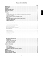
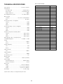
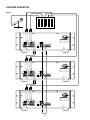
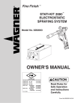
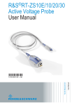
Model PMD520 User Guide
3-Head Double Cassette Deck
R
1
CAUTION
RISK OF ELECTRIC SHOCK
DO NOT OPEN
CAUTION: TO REDUCE THE RISK OF ELECTRIC SHOCK,
DO NOT REMOVE COVER (OR BACK)
NO USER-SERVICEABLE PARTS INSIDE
REFER SERVICING TO QUALIFIED SERVICE PERSONNEL
The lightning flash with arrowhead symbol, within
an equilateral triangle, is intended to alert the user
to the presence of uninsulated “dangerous voltage”
within the product’s enclosure that may be of sufficient magnitude to constitute a risk of electric shock
to persons.
The exclamation point within an equilateral triangle
is intended to alert the user to the presence of
important operating and maintenance (servicing)
instructions in the literature accompanying the
appliance.
WARNING
TO REDUCE THE RISK OF FIRE OR ELECTRIC SHOCK,
DO NOT EXPOSE THIS APPLIANCE TO RAIN OR MOISTURE.
CAUTION: TO PREVENT ELECTRIC SHOCK, MATCH WIDE
BLADE OF PLUG TO WIDE SLOT, FULLY INSERT.
ATTENTION: POUR ÉVITER LES CHOCS ÉLECTRIQUES,
INTRODUIRE LA LAME LA PLUS LARGE DE LA FICHE DANS LA
BORNE CORRESPON-DANTE DE LA PRISE ET POUSSER
JUSQU’AU FOND.
NOTE:
― Reorient or relocate the receiving antenna.
This equipment has been tested and found to comply with the
limits for a Class B digital device, pursuant to part 15 of the
FCC Rules. These limits are designed to provide reasonable
protection against harmful interference in a residential
installation. This equipment generates, uses and can radiate
radio frequency energy and, if not installed and used in
accordance with the instructions, may cause harmful
interference to radio communications. However, there is no
guarantee that interference will not occur in a particular
installation.
If this equipment does cause harmful interference to radio or
television reception, which can be determined by turning the
equipment off and on, the user is encouraged to try to correct
the interference by one or more of the following measures:
― Increase the separation between the equipment and
receiver.
― Connect the equipment into an outlet on a circuit different
from that to which the receiver is connected.
― Consult the dealer or an experienced radio/TV technician
for help.
NOTE:
Changes or modifications may cause this unit to fail to comply
with Part 15 of the FCC Rules and may void the user's
authority to operate the equipment.
2
SAFETY
INSTRUCTIONS
READ BEFORE OPERATING EQUIPMENT
12. Grounding or Polarization — The precautions that should
be taken so that the grounding or polarization means of an
appliance is not defeated.
This product was designed and manufactured to meet strict
quality and safety standards. There are, however, some installation and operation precautions which you should be particularly aware of.
1. Read Instructions — All the safety and operating instructions should be read before the appliance is operated.
2. Retain Instructions — The safety and operating instructions should be retained for future reference.
AC POLARIZED PLUG
3. Heed Warnings — All warnings on the appliance and in
the operating instructions should be adhered to.
13. Power-Cord Protection — Power-supply cords should be
routed so that they are not likely to be walked on or
pinched by items placed upon or against them, paying particular attention to cords at plugs, convenience receptacles, and the point where they exit from the appliance.
4. Follow Instructions — All operating and use instructions
should be followed.
5. Water and Moisture — The appliance should not be used
near water — for example, near a bathtub, wash-bowl,
kitchen sink, laundry tub, in a wet basement, or near a
swimming pool, etc.
14. Cleaning — The appliance should be cleaned only as recommended by the manufacturer.
15. Power Lines— An outdoor antenna should be located
away from power lines.
6. Carts and Stands — The appliance should be used only
with a cart or stand that is recommended by the manufacturer.
16. Outdoor Antenna Grounding — If an outside antenna is
connected to the receiver, be sure the antenna system is
grounded so as to provide some protection against voltage surges and built up static charges. Section 810 of the
National Electrical Code, ANSI/NFPA No. 70-1984, provides information with respect to proper grounding of the
mast and supporting structure, grounding of the lead-in
wire to an antenna discharge unit, size of grounding conductors, location of antenna-discharge unit, connection to
grounding electrodes, and requirements for the grounding
electrode. See Fig. 1.
7. An appliance and cart combination should be moved with
care. Quick stops, excessive force, and uneven surfaces
may cause the appliance and cart combination to overturn.
17. Nonuse Periods — The power cord of the appliance
should be unplugged from the outlet when left unused for
a long period of time.
8. Wall or Ceiling Mounting — The appliance should be
mounted to a wall or ceiling only as recommended by the
manufacturer.
18. Object and Liquid Entry — Care should be taken so that
objects do not fall and liquids are not spilled into the enclosure through openings.
9. Ventilation — The appliance should be situated so that its
location or position does not interfere with its proper ventilation. For example, the appliance should not be situated on a bed, sofa, rug, or similar surface that may block
the ventilation openings; or, placed in a built-in installation, such as a bookcase or cabinet that may impede the
flow of air through the ventilation openings.
19. Damage Requiring Service — The appliance should be
serviced by qualified service personnel when:
A. The power-supply cord or the plug has been damaged;
or
B. Objects have fallen, or liquid has spilled into the appliance; or
C. The appliance has been exposed to rain; or
10. Heat — The appliance should be situated away from heat
sources such as radiators, heat registers, stoves, or
other appliances (including amplifiers) that produce
heat.
D. The appliance does not appear to operate normally or
exhibits a marked change in performance; or
E. The appliance has been dropped, or the enclosure
damaged.
11. Power Sources — The appliance should be connected to
a power supply only of the type described in the operating
instructions or as marked on the appliance.
20. Servicing — The user should not attempt to service the
appliance beyond that described in the operating instructions. All other servicing should be referred to qualified
service personnel.
3
FIG. 1
EXAMPLE OF ANTENNA GROUNDING ACCORDING TO
NATIONAL ELECTRICAL CODE INSTRUCTIONS
CONTAINED IN ARTICLE 810 - “RADIO AND TELEVISION EQUIPMENT”
ANTENNA
LEAD IN
WIRE
GROUND
CLAMP
ANTENNA
DISCHARGE UNIT
(NEC SECTION 810–20)
ELECTRIC
SERVICE
EQUIPMENT
GROUNDING CONDUCTORS
(NEC SECTION 810–21)
GROUND CLAMPS
POWER SERVICE GROUNDING
ELECTRODE SYSTEM
(NEC ART 250, PART H)
NEC – NATIONAL ELECTRICAL CODE
This Class B digital apparatus meets all requirements of the
Canadian Interference - Cansing Equipment Regulations.
Cet appareil numérique de la Classe B respecte toutes les
exigences du Règlement sur le matériel brouilleur du Canada.
NOTE TO CATV SYSTEM INSTALLER:
This reminder is provided to call the CATV system installer’s attention to Article 820–40 of the NEC that
provides guidelines for proper grounding and, in particular, specifies that the cable ground shall be connected
to the grounding system of the building, as close to the point of cable entry as practical.
4
Dolby noise reduction and HX Pro headroom extension are manufactured under license from Dolby Laboratories
Licensing Corporation. HX Pro originated by Bang & Olufsen.
“DOLBY” the double-D symbol and “HX PRO” are trademarks of Dolby Laboratories Licensing Corporation.
is a registered trademark.
Printed in Japan
5
98 / 10 MIT
418S851252
TABLE OF CONTENTS
Page
INTRODUCTION ............................................................................................................................................................. 6
PRECAUTIONS .............................................................................................................................................................. 6
FEATURES ..................................................................................................................................................................... 6
REAR PANEL CONNECTIONS ...................................................................................................................................... 7
English
DISPLAYS ....................................................................................................................................................................... 9
OPERATION ................................................................................................................................................................. 10
PLAYBACK ............................................................................................................................................................... 10
PLAYBACK ON ONE WELL (Same procedure for Well A or Well B) OR BOTH WELLS .................................... 10
CONTINUOUS PLAYBACK ................................................................................................................................. 10
TIMER PLAYBACK (Same procedure for Wells A and B) .................................................................................... 10
RECORDING ............................................................................................................................................................ 10
SINGLE WELL RECORDING (Same procedure for Well A or Well B) ................................................................ 10
CONTINUOUS RECORDING ............................................................................................................................... 11
PARALLEL RECORDING ..................................................................................................................................... 11
TIMER RECORDING (Same procedure for Wells A and B) ................................................................................. 11
OVERLAP SERIES RECORDING ........................................................................................................................ 11
CASCADE OPERATION .......................................................................................................................................... 12
CASCADE CONTINUOUS PLAYBACK ............................................................................................................... 12
CASCADE CONTINUOUS RECORDING ........................................................................................................... 12
SYNCHRONOUS RECORDING .............................................................................................................................. 12
CASCADE OVERLAP SERIES RECORDING ......................................................................................................... 12
OTHER OPERATIONS ............................................................................................................................................. 13
ERASURE OF TAPE ............................................................................................................................................ 13
AUTO TAPE SELECTOR ..................................................................................................................................... 13
AUTOMATIC BIAS ADJUST ................................................................................................................................ 13
TAPE STOP ALARM ............................................................................................................................................ 13
AUTO COUNTER RESET ................................................................................................................................... 13
TO PROTECT VALUABLE RECORDINGS ......................................................................................................... 13
ENHANCED REMOTE CONTROL OPERATIONS .................................................................................................. 13
SIMULTANEOUS (PARALLEL) RECORDING ..................................................................................................... 13
DUPLICATION SYNCHRONIZATION ...................................................................................................................... 14
CONNECTION ..................................................................................................................................................... 14
NORMAL SPEED DUPLICATION ........................................................................................................................ 14
HIGH SPEED DUPLICATION .............................................................................................................................. 14
QMS (QUICK MUSIC SEARCH) .............................................................................................................................. 14
AUTO BIAS & EQ SYSTEM .......................................................................................................................................... 15
CARE AND MAINTENANCE ......................................................................................................................................... 16
MAINTENANCE ....................................................................................................................................................... 16
HEAD CLEANING ................................................................................................................................................ 16
HEAD DEMAGNETIZATION ................................................................................................................................ 16
CLEANING OF EQUIPMENT EXTERNAL SURFACES ...................................................................................... 16
REPAIRS ....................................................................................................................................................................... 16
TROUBLESHOOTING .................................................................................................................................................. 16
TECHNICAL SPECIFICATIONS ................................................................................................................................... 53
FRONT AND REAR PANEL DRAWINGS ..................................................................................................................... 54
5
English
FRONT PANEL FEATURES ........................................................................................................................................... 7
English
Thank you for selecting the Marantz Model PMD520 3-head Independent Dual Well Cassette Deck.
Please read these operating instructions carefully. We recommend that you read the entire user guide before you connect or
operate the unit.
After you have reviewed the contents this manual, we suggest
that you make all system connections before you attempt to
operate the unit.
Refer to the Figures on Pages 54 – 57 of this user guide.
The callout numbers on the Figures correspond to those found
in the text. All references to connections and controls are printed
in BOLD type, as they appear on the unit.
¡ OVERLAP SERIES RECORDING
This feature records long events such as a conference, without interruption. The recording of the next tape starts when
the remaining time on the previous tape is approximately 3
minutes.
¡ PARALLEL RECORDING (DUPLICATION)
When multiple copies of the same source are required, it is
possible to record both Well A and Well B simultaneously, in
parallel, from a single source.
PRECAUTIONS
¡ TIMER REC/PLAY
Time-activated playback and recording are available using
a commercially available timer.
The following precautions should be considered when operating the equipment.
When setting the equipment ensure that :
¡ FINE SPEED CONTROL
Each Well features ± 3% speed control.
– air is allowed to circulate freely around the equipment
– the equipment is on a vibration free surface
¡ METERS AND LINEAR TIME TAPE COUNTERS
Each Well features independent FL bargraph meters, and a
linear time (minutes and seconds) counter. The display on
these counters is only an approximate indication of minutes
and seconds and its accuracy depends on the match between the Tape and the correct TAPE TIME setting.
– the equipment will not be exposed to interference from an
external source
– the equipment will not be exposed to excessive heat, cold,
moisture or dust
– the equipment will not be exposed to direct sunlight
– the equipment will not be exposed to electrostatic discharges
¡ TAPE STOP ALARM
A buzzer sound is generated to indicate the end of tape after playback or recording.
¡ In addition, never place heavy objects on the equipment.
¡ If a foreign body or water does enter the equipment, contact
your nearest dealer or service center.
¡ DOLBY B/C NR SYSTEMS
The Dolby NR (Noise Reduction) systems compress and amplify signals during recording in order to raise the signal-tonoise ratio on the tape. During playback, these signals are
expanded and attenuated by the same amount in order to
regain the original dynamic range of the music. An additional
result of this expansion and attenuation is that the noise floor
of the recording is reduced significantly. Dolby B typically
reduces noise by 10 dB, while Dolby C typically reduces
noise by 20 dB.
¡ Do not pull out the plug by pulling on the mains lead. Hold
the plug.
FEATURES
¡ COMPLETELY INDIVIDUAL DUAL SYSTEM
Well A and Well B can be controlled independently for both
recording and playback. There are two sets of inputs and
outputs which allow for many modes of recording and playback. Two separate input sources can be recorded simultaneously and independently on the two decks; two different
tapes can be played back simultaneously on the two decks;
and lastly, it is possible to play a cassette on one well, and
record a different source (such as a mixer) on the other well
simultaneously.
There are also several modes in which the two decks work
together.
¡ DOLBY HX PRO HEADROOM EXTENSION
The Dolby HX PRO system monitors the total amount of effective bias during recording and instantaneously compensates for any excess bias by reducing the deck’s bias signal
level accordingly.
The system operates independently on each channel. HX
PRO is unlike a noise reduction system because it functions
only during recording and no decoding is required. Therefore, a tape recorded with the HX PRO system can be played
back on any other cassette deck while retaining the benefits
of HX PRO.
Dolby noise reduction and HX Pro headroom extension are
manufactured under license from Dolby Laboratories Licensing Corporation. HX Pro originated by Bang & Olufsen.
“DOLBY” the double-D symbol and “HX PRO” are trademarks
of Dolby Laboratories Licensing Corporation.
¡ CONTINUOUS RECORDING AND PLAYBACK
In the continuous mode, Well A will play (or record) side one,
and then automatically switch to Well B, which will play (or
record) side one. In this way 1-1/2 hours of uninterrupted
playback or recording is possible using C-90 cassettes.
6
English
¡ CASCADE CONNECTION FOR SERIAL CONNECTION OF
MULTIPLE UNITS
By connecting several PMD520s in series by way of the cascade connection, multiple units can play or record continuously for logging and other long-time recording applications.
In this case, Wells A and B of unit #1 will play (or record) as
in the example above, then they will trigger the start of continuous playback (or record) of unit #2, and so on.
INTRODUCTION
Pin No.
1
2
3
4
5
6
7
8
9
10
11
12
13
A DECK A/B LINE INPUT
These jacks should be connected to LINE OUTPUT of your
source.
English
Note:
Short pins are installed from the factory in the Deck B INPUT.
The short pins should be removed only if an input source is
connected directly to Deck B. They have been installed to
avoid crosstalk from one deck to the other, in case one deck
is recording and the other deck is playing back.
B DECK A/B LINE OUTPUT
These jacks should be connected to the LINE INPUT of your
PA or monitoring system.
Function
REW A IN
REW B IN
FF A IN
FF B IN
PLAY A IN
PLAY B IN
STOP A IN
STOP B IN
REC A IN
REC B IN
REC MUTE A IN
REC MUTE B IN
A+B REC IN
Pin No.
14
15
16
17
18
19
20
21
22
23
24
25
Function
NORM IN
HIGH IN
AUTO REW IN
TAPE TIME A IN
TAPE TIME B IN
COUNTER RESET A IN
COUNTER RESET B IN
AUTO BIAS A IN
AUTO BIAS B IN
HIGH OUTPUT
GND
A+B OUTPUT
¡ All input is active low.
¡ All output is open collector.
C LOOP THROUGH A OUTPUT
These jacks output the same signal input to the LINE INPUT
jacks of Well A as they are input.
I AC POWER INPUT
Connect one end of the power cord to this receptacle.
D INPUT SELECT SWITCH
This switch selects the input mode for the LINE INPUT jacks.
¡ Position A, B
: Deck A receives its input from LINE A.
Deck B receives its input from LINE B.
¡ Position A
: Both decks receive the same input from
LINE INPUT A.
FRONT PANEL FEATURES
q POWER SWITCH
E RC-5 REMOTE CONTROL JACKS
For switching the unit on and off.
These jacks are for use with the remote control accessories.
Connect the output of an RC-5 based remote control to the
RC-5 input of the PMD520. The RC-5 output of the PMD520
may be connected to the RC-5 input of other machines for
multiple-machine control from the same remote control accessory.
Refer to the specifications for the complete RC-5 command
set.
w CASSETTE HOLDER A/B
Insert cassettes into these holders with the exposed tape
facing downward.
e CONTROL BUTTONS
F EXT (EXTENSION) REMOTE CONTROL JACKS
This jack is used to cascade several PMD520s for continuous serial recording and playback.
Connect the EXT OUT jack to the EXT IN jack of the next unit
in the chain.
STOP
Press this button to cancel any operation modes and to stop
tape travel.
PLAY
Press this button to start playback.
G MPX FILTER SWICH
FAST WIND
Press these buttons to fast wind in the direction of the arrows. If the Well is in play mode, these buttons will place the
well in CUE/REVIEW Mode. In CUE/REVIEW mode, if these
buttons are pressed the Well will enter the fast wind mode.
When recording FM broadcasts, set this switch to ON.
H PARALLEL CONTROL I/O
These terminals contain a control signal input for almost all
of the operations of the unit and output the A+B and HIGH
signals.
The application range of this unit can be expanded greatly
by using these terminals properly.
13 12 11 10 9
8
7
6
5
4
3
2
REC
Press this button to enter the REC-PAUSE mode. Press PLAY
to initiate recording. Press this button again to re-enter the
REC-PAUSE mode.
1
REC MUTE
When in REC-PAUSE mode, press this button to record 3
seconds of no sound.
25 24 23 22 21 20 19 18 17 16 15 14
7
English
CONTROL I/O Pin assign
REAR PANEL CONNECTIONS
r COUNTER BUTTONS
i TAPE SPEED BUTTONS
These switches determine the playback/recording speed of
tapes in both Wells A and B.
¡ TAPE TIME
This button changes the reference time of tape (tape type)
so that the time counter can show accurate time information. The initial setting when the unit is turned on is "60".
The first press of this button displays the current setting.
Every time this button is pressed while the time setting is
displayed, it is changed in a cyclic order of 60 → 90 → 120
→ 10 → 20 → 30 → 46 → 60...
English
¡ NORM
Press this button to set the tape speed for duplication to
1-7/8 ips (4.75 cm/sec).
The NORM indicator lights up when NORM is selected.
¡ RESET
Pressing this button will reset the counter time to 00.00 (0
minutes, 0 seconds).
t AUTO REW (AUTO REWIND) BUTTON
o OVERLAP REC (OVERLAP RECORD) BUTTON
Used to switch the auto rewind mode ON or OFF.
The indicator lights up when the auto rewind mode is on.
When the auto rewind mode is on, each well enters rewind
mode upon detection of the end of tape.
The auto rewind mode is switched on or off simultaneously
for both Wells A and B.
The initial setting is off.
Pressing the OVERLAP REC button when the continuous
mode is "
" or "
" switches the overlap series recording
mode alternately to Off → On → Off. The OVERLAP REC
indicator lights up when the overlap series recording mode
is on.
The operation in the overlap series recording mode is variable depending on the current continuous mode.
y CONT (CONTINUOUS) BUTTON
!0 MONITOR BUTTONS
Used to switch the continuous mode ON or OFF.
Every time this button is pressed, the CONT indicator status
changes in cycle of On → Blinking → Off → On...
The lighting of the indicator indicates that the continuous
mode of PMD520 is "
". (A → B → C → D → E →...)
The blinking of the indicator indicates that its continuous
mode is "
". (A → B → A → B → A →...)
The initial setting when the unit is turned on is off.
Pressing the PLAY
or REC
button while the continuous mode is on starts continuous playback or continuous
recording.
Pressing this button switches the monitoring mode between
Tape and Source.
The MONITOR indicator lights up when monitoring from the
tape, and is off when monitoring from the input source.
The initial setting when the unit is turned on is tape monitor.
!1 BIAS RESET BUTTONS
Used to reset the bias setting to the factory setting.
The indicator is off when the factory-set bias setting is used.
The indicator will light up after the Auto Bias program is run.
u A+B REC BUTTON
!2 DOLBY NR B/C SELECTORS
Check to insure that both wells are in STOP mode prior to
pressing the A+B REC button.
Pressing the A+B REC button once will cause both wells to
enter a REC-PAUSE mode to adjust recording levels. Pressing the A+B REC button a second time, will cause both wells
to enter a REC mode simultaneously. Pressing the A+B REC
button a third time, will cause both wells to enter a RECPAUSE mode again and pressing the A+B REC button a
fourth time , will resume the REC mode.
This switch is used to select Dolby B or C noise reduction
for recording or playback.
Most commercially available cassettes which display the
double-D symbol are encoded with Dolby B noise reduction.
Note:
When the TAPE SPEED is set to HIGH, the Dolby NR is
switched off regardless of the position of the selectors.
8
English
¡ HIGH
Press this button to set the tape speed for duplication to
3-6/8 ips (9.5 cm/sec).
The HIGH indicator lights when HIGH is selected.
When HIGH is selected, Dolby NR is disabled.
!3 TIMER
DISPLAYS
This switch is used to set the timer operation mode.
a TAPE TIME COUNTERS
¡ OFF
No timer operation is used when the switch is set to this
position.
These counters display the tape position for each Well in
Minutes and Seconds.
b BARGRAPH LEVEL METERS
These meters display the signal levels for each Well in stereo.
¡ PLAY
Timer playback operation is activated when the switch is
set to this position. The tape will automatically start playing
when the power is switched on.
c AUTO REW INDICATOR
These indicators will light up when the AUTO REW mode
button t is pressed.
!4 REC LEVEL CONTROL
For adjusting the record input level.
d CONT (CONTINUOUS) INDICATORS
These indicators will light up when the CONT mode button
y is pressed.
!5 REC BALANCE CONTROL
Used to adjust the left-right balance of channels while recording.
e A+B INDICATOR
These indicators will light up when the A+B mode button u
is pressed.
!6 FINE SPEED
Each well features ± 3% speed control.
f TAPE SPEED INDICATORS
!7 PHONES SELECTOR SWITCH
¡ HIGH SPEED INDICATOR
This indicator will light up when the HIGH SPEED mode
button i is pressed.
This switch allows you to select Well A, Well B, or a mix of
both Wells (A+B) in the phones.
¡ NORMAL SPEED INDICATOR
This indicator will light up when the NORMAL SPEED mode
button i is pressed.
!8 PHONES LEVEL CONTROL
This control adjusts the volume of the headphone output.
g OVERLAP RECORDING INDICATOR
!9 PHONES JACK
This indicator will light up when the OVERLAP REC mode
button o is pressed.
Use this jack to connect a pair of headphones with a stereo
1/4" connector.
h MONITOR INDICATORS
These indicators will light up when in the TAPE MONITOR
mode.
i BIAS RESET INDICATORS
These indicators will light up after the BIAS RESET program
is run.
9
English
English
¡ REC
Timer recording operation is activated when the switch is
set to this position. The tape will automatically start recording when the power is switched on.
RECORDING
PLAYBACK
SINGLE WELL RECORDING
(Same procedure for Well A or Well B)
PLAYBACK ON ONE WELL (Same procedure for Well
A or Well B) OR BOTH WELLS
1. Insert a blank cassette into the cassette holder(s).
1. Set the POWER button to ON.
2. Reset the tape counter by pressing the RESET button.
2. Insert a prerecorded cassette in the cassette holder(s).
3. If you wish to use Dolby NR, set the DOLBY NR switches
accordingly.
3. Reset the tape counter by pressing the RESET button.
English
4. Press the REC
4. If the tape has been encoded with Dolby NR, set the DOLBY
NR switches accordingly.
5. Press the PLAY
button to play the cassette.
6. Press the STOP
button to stop playback.
button to enter REC-PAUSE mode.
5. Adjust the record level using the REC LEVEL control, so that
the red LEDs light only at peaks in the music.
6. Press the PLAY
button to initiate RECORD.
7. Press the STOP
button to end recording, or press REC
again to re-enter REC-PAUSE mode.
Note:
Be aware of the setting of the input select switch on the rear
panel.
CONTINUOUS PLAYBACK
1. Set the POWER button to ON.
2. Insert recorded cassettes into both Wells.
¡ A, B Position
3. If the tape has been encoded with Dolby NR, set the DOLBY
NR switches accordingly.
: Well A receives input from input A, Well B
receives input from input B.
¡ A Position
: Both wells receive input from input A.
4. Press the CONT button to select the continuous mode. The
lighting of the CONT indicator indicates the "
" mode and
the blinking indicates the "
" mode.
Tape Types and Length
5. Press one of PLAY
buttons. Playback will start. When that
Well finishes playing , the second well will begin playing.
Any type of tape (Normal, High, or Metal) can be used with the
PMD520. High or Metal tapes have superior performance compared to Normal Tapes. The PMD520 can sense which kind of
tape is being used, and will automatically adjust bias, EQ, etc.
C-60 or C-90 length tapes are recommended, as C-120 tapes
are often too thin, and can become entangled in the transport
mechanism.
6. When the continuous mode is "
", the tape stops after the
second well is finished or triggers another deck via the EXT
output.
7. When the continuous mode is "
" and the AUTO REW mode
is on, the tape in the first well that has been rewound is played
after the second well is finished.
8. Press the STOP
Remote Operation
to stop playback.
The period ( 0 0 . 0 0 ) of the time display will flash depending
on which Well is being addressed by a conected remote control.
9. Press CONT to cancel CONT mode.
Note:
During continuous playback, the signal from both wells goes
to line output A.
TIMER PLAYBACK (Same procedure for Wells A and B)
1. Connect the power cord of this unit to a timer.
2. Insert a prerecorded cassette in the cassette holder(s).
3. If you wish to use Dolby NR, set the DOLBY NR switches to
select B- or C-type noise reduction.
4. Set the POWER switch of this unit to ON.
5. Set the TIMER switch to the PLAY position.
6. Set the timer to the desired time.
7. When the set time comes and the timer turns on, power is
supplied to the unit and playback starts automatically.
Note:
Use a timer which can turn on at the desired time of the day.
10
English
OPERATION
CONTINUOUS RECORDING
TIMER RECORDING
(Same procedure for Wells A and B)
1. Insert blank cassettes into both Wells. Be sure that both decks
are rewound.
1. Connect the power cord of this unit to a timer.
2. Insert a blank cassette in the cassette holder(s).
3. Reset the tape counters to "00.00" by pressing the RESET
buttons.
4. If you wish to use Dolby NR in your recording, set the DOLBY
NR switches to select B- or C-type noise reduction.
4. Press the CONT button. Pressing it once sets the "
" mode,
in which the indicator lights up. Pressing it twice sets the
"
" mode, in which the indicator blinks.
5. Press the REC
5. Press the REC
mode.
7. Set the TIMER switch to the REC position.
3. Set the POWER button to on.
6. While observing the level meter, adjust the REC LEVEL Control.
buttons of both wells to enter REC-PAUSE
8. Set the timer to the desired time.
6. Adjust the record level using the REC LEVEL control.
7. Press the PLAY
9. When the set time comes and the timer turns on, power is
supplied to the unit and recording starts automatically.
button on Well A to initiate RECORD.
8. When the tape in Well A is finished, recording starts automatically in Well B. If the continuous mode is "
", recording
ends when tape in Well B is finished and another deck is
triggered with the EXT output. If the continuous mode is "
",
recording in Well A restarts at the moment recording in Well
B is finished. At this time, the tape in Well A should be reversed manually or replaced with a new tape.
9. Press STOP
button to enter record-pause mode.
Note:
Use a timer which can turn on at the desired time of the day.
OVERLAP SERIES RECORDING
1. Insert blank cassettes in the cassette holders of both wells.
button to end the Recording.
2. Press the CONT button. Pressing it once sets the "
" mode,
in which the indicator lights up. Pressing it twice sets the
"
" mode, in which the indicator blinks.
10. Press the CONT button to cancel continuous mode.
Note:
All input for continuous recording will come from Line Input A.
3. Press the OVERLAP REC button. The OVERLAP REC indicator lights up to indicate the overlap series recording mode.
4. Press the REC
pause mode.
PARALLEL RECORDING
buttons of Wells A and B to enter record-
5. In record-pause mode, adjust the REC LEVEL controls of
both wells.
1. Insert blank cassettes into both Wells. Be sure that both decks
are rewound.
6. Press the PLAY
button of Well A or B to start recording.
7. When the remaining time on the tape in the first Well is approximately 3 minutes, the other well starts recording automatically.
2. If you wish to use noise reduction, set the DOLBY NR switches
accordingly.
3. Reset the tape counters to “00.00” by pressing the RESET
buttons.
8. If the auto rewind mode is switched on, the finished tape is
rewound automatically to the beginning. If the auto rewind
mode is off, reverse the finished tape manually to prepare
for the next recording.
4. Press the A+B REC button. This will set both Wells for record,
and the REC lights will blink.
5. Adjust the record level using the REC LEVEL control.
9. To terminate the overlap series recording mode, press the
OVERLAP REC button again.
6. Press the A+B button again to start the recording.
7. Press both STOP
buttons to stop recording, or press the
A+B button to re-enter record-pause mode.
Note:
If AUTO REW is activated during the "
" mode or the continuous loop is fed back to the first deck, the information recorded will be erased and recorded over.
Note:
All input for parallel recording will come from Line Input A.
11
English
English
2. If you wish to use noise reduction, set the DOLBY NR switches
accordingly.
SYNCHRONOUS RECORDING
Refer to Fig. 5
CASCADE CONTINUOUS PLAYBACK
Synchronous Recording is possible only when this unit is connected with a Marantz Professional product equipped with the
Sync Recording function.
The Synchronous Recording connection consists of a single RCA
cable which runs to the RC-5 REMOTE input jack on the rear
panel of the PMD520, from the REMOTE output jack on the rear
panel of the Marantz source.
1. Set the POWER button to ON.
English
2. Connect the EXT output of the first unit into the EXT input of
the second unit.
Then connect the EXT output of the second deck into the
next unit in the chain or back into the first unit.
1. Set the POWER button to ON.
3. Insert recorded cassettes into all wells.
2. Insert blank cassettes into the appropriate Wells.
4. If the tape has been encoded with Dolby NR, set the DOLBY
NR switches accordingly.
3. If the tape has been encoded with Dolby NR, set the DOLBY
NR switches accordingly.
5. Press the CONT buttons on all units. The CONT Indicator will
light.
4. press the REC
button on the appropriate Wells of the unit.
Check to see that REC-PAUSE mode is indicated.
When recording two tapes in parallel, press the A+B button
instead the REC
button.
6. Press the PLAY
button of Well A, of Unit #1.
7. When Well A of Unit #1 finishes, Well B of Unit #1 will start
automatically.
5. Adjust the recording level with source playing.
6. Press the PLAY
8. When Well B of Unit #1 finishes, Well A of Unit #2 will start
automatically.
9. To stop playback, press the CONT button, and STOP
buttons on all units.
button of the source player.
CASCADE OVERLAP SERIES RECORDING
Note:
Output from both Wells of each unit will be sent to LINE Output A on each unit. Line output B is not used on any unit.
1. Connect the units as shown in Figure 6.
2. Insert blank cassettes in both Wells A and B of all the connected units.
3. Press the CONT button of all the units so that their CONT
indicator light up (the continuous mode is "
").
CASCADE CONTINUOUS RECORDING
4. Press the OVERLAP REC buttons of the all the units.
The OVERLAP REC indicators light up to indicate the overlap series recording mode.
1. Set the POWER button to ON.
2. Connect the EXT output of the first unit into the EXT input of
the second unit.
Then connect the EXT output of the second deck into the
next unit in the chain or back into the first unit.
5. Press the REC
buttons of both Wells A and B of all the
units to put all the wells in record-pause mode.
6. Adjust the REC LEVEL controls of Wells A and B in recordpause mode.
3. Insert recorded cassettes into all wells.
7. Press the PLAY
recording.
4. If the tape has been encoded with Dolby NR, set the DOLBY
NR switches accordingly.
8. When the remaining time on the tape in the first well becomes
about 3 minutes, the other well starts recording automatically.
5. Press the CONT buttons on all units. The CONT Indicator will
light.
6. Press the REC
buttons on both Wells of each unit. Check
to see that every Well indicates REC-PAUSE mode.
9. Similarly, when the remaining time on the tape in the second
well of unit #1 is approximately 3 minutes, Well A of unit #2
starts recording automatically.
7. Adjust the recording level of each Well.
8. Press the PLAY
button of Well A or B of unit #1 to start
button on Well A of Unit #1.
10. If the auto rewind mode is switched on, the finished tape is
rewound automatically to the beginning. If the auto rewind
mode is off, reverse the finished tape manually to prepare for
the next recording.
9. When Well A of Unit #1 finishes, Well B of Unit #1 will start
automatically.
10. When Well B of Unit #1 finishes, Well A of Unit #2 will start
automatically.
11. To terminate the overlap series recording mode, press the
OVERLAP REC button again.
11. To stop Recording , press the CONT button, and STOP
buttons on all units.
12. To terminate the continuous mode, press the CONT button
twice.
Note:
Input to both Wells of each unit will be received from Line
Input A on each unit. Line Input B is not used on any unit.
Note:
If AUTO REW is activated during the "
" mode or the continuous loop is fed back to the first deck, the information recorded will be erased and recorded over.
12
English
CASCADE OPERATION
Error Message
OTHER OPERATIONS
If a problem occurs during the AUTOMATIC BIAS routine,
an Error message will appear on the display. Please refer
to the following table.
¡ If you must stop playback or recording in the middle of a tape,
be sure to press the STOP
button first, then turn the power
off. If the power is turned off in the middle of an operation, the
cassette tape remains loaded, and it may be impossible to
eject. In such a case, turn the power on, enter PLAY mode,
then press STOP
button, and then eject the tape.
Err No.
English
¡ The same caution as above applies in cases of power failure.
To prevent damage, never attempt to force the removal of a
cassette while the power is off.
Meaning
Err 1
Tape End Error
Err 2
Internal Oscillator Error
Err 3
Bias setting Error
Err 4
REC EQ Adjust Error
Err 5
Total Adjust Error
Errors 2-5 are probably the result of a bad tape. Please rerun
the AUTO BIAS program with a different tape.
ERASURE OF TAPE
When a program source is recorded onto a tape, the previously
recorded sound is erased automatically, and replaced with the
new recording. If you wish to erase a tape without recording,
set the REC LEVEL control to the minimum (0) position or remove the input source, and let the tape travel in the REC mode.
TAPE STOP ALARM
When either Well A or B reaches the end of a tape, the PMD520
generates a buzzer sound to indicate it.
AUTO TAPE SELECTOR
AUTO COUNTER RESET
This unit is equipped with auto tape selector which automatically sets the bias and equalizer level using the detection holes
provided in the cassette shell. The bias and equalizer level is
automatically set according to the type of cassette as follows.
(See Figure 7)
¡ Normal tapes
¡ High tapes
¡ Metal tapes
When a cassette is removed from a cassette holder and another tape is inserted, the tape counter is reset automatically to
"00:00".
EQ ; 120 µS , Bias ; Low
EQ ; 70 µS , Bias ; High
EQ ; 70 µS , Bias ; Metal
TO PROTECT VALUABLE RECORDINGS
In the record mode, information previously recorded on the tape
will automatically be erased. To prevent this from happening,
use a small screwdriver to break out one or both safety tabs
(See Figure 8). It is possible to restore the recording capability
of either side of the cassette by covering the opening with clear
adhesive tape (See Figure 9).
AUTOMATIC BIAS ADJUST
With this feature, the microcomputer built into the PMD520 adjusts the bias and record gain automatically so that the characteristics of the tape in use can be exhibited fully. (Refer to page
15 for more information)
1. Insert the cassette in the cassette holder of the well to be
subjected to bias setting.
ENHANCED REMOTE CONTROL OPERATIONS
2. While holding down the REC
button.
SIMULTANEOUS (PARALLEL) RECORDING
button Press the REC MUTE
Check to insure that both wells are in REC PAUSE mode after
pressing the A+B REC button on the front of the unit. The unit
will start recording when either a PLAY or A+B command from
the remote controller has been received. During the REC mode,
the unit can be placed into a REC PAUSE mode by sending a
PAUSE, A+B, or REC command from the remote controller and
started again by a PLAY or A+B command from the remote
controller. Pressing the STOP
button on the front of the unit
or sending a STOP command from the remote controller will
cancel this operation.
3. Ab will appear on the display followed by a number that will
count down until the adjustment is complete.
4. If an Error occurs during this process, please refer to the
next section.
5. When the bias has been set, the BIAS RESET indicator lights
up.
6. To reset the bias to the factory setting, press the BIAS RESET button. The indicator is extinguished and the factoryset bias is recalled.
7. To return to the set bias, press the BIAS RESET button so the
indicator lights up.
8. To change the bias setting, start the adjustment from the beginning.
13
English
Caution:
DUPLICATION SYNCHRONIZATION
HIGH SPEED DUPLICATION
Refer to Fig. 6
CONNECTION
1. Insert the master tape in Well A of unit #1.
2. Insert the blank cassettes in both Wells A and B of units #2
and after.
1. Connect the WRC220 * to the RC-5 IN jack of unit #1.
3. Press the TAPE SPEED HIGH buttons of all the units so that
the HIGH indicators of all the units light up.
2. Connect the RC-5 OUT jack of unit #1 with the RC-5 IN jack
of unit #2.
English
5. Press the A+B button of the WRC220. All the slave units enter record-pause mode.
4. Up to 100 units can be connected in the same way as described above.
6. Set the REC LEVEL controls of the slave units to the center
click positions. See Note 2 below.
5. Connect the DECK A OUTPUT jacks of unit #1 with the DECK
A INPUT jacks of unit #2.
7. Press the TAPE A button of the WRC220. This button should
be pressed only once and need not be pressed even when
duplication is performed later.
button of the WRC220. The master tape
Press the PLAY
in Well A of unit #1 starts to be played and both Wells A and
B of the units #2 and after start recording.
6. Connect the LOOP THROUGH A OUT jacks of unit #2 with
the DECK A INPUT jacks of unit #3.
7. Similarly, connect the LOOP THROUGH OUT and DECK A
INPUT jacks of other units up to unit #100.
8. Set the INPUT SELECT switches of units #2 and after to A.
8. To stop duplication, press the STOP button of the WRC220.
* WRC220 is sold separately.
Notes
Observe the following notes when dubbing a Dolby NR encoded
master tape at high speed.
NORMAL SPEED DUPLICATION
1) Dolby NR has a special dynamic characteristic (with respect
to the time axis) by responding to the frequency and level
and can process signals correctly only in real time. However,
as the high speed duplication alters the relationship between
the audio signals and time considerably, the Dolby NR is
switched automatically off in the high speed duplication mode.
If the source was recorded with Dolby NR, the copies will be
recorded with the same Dolby NR.
1. Insert the blank cassettes in both Wells A and B of all units.
2. Press the TAPE SPEED NORM buttons of all the units so
that the NORMAL indicators of all the units light up.
3. Set the DOLBY NR switches to the desired setting on all the
units to record the tapes with noise reduction.
4. Press the A+B button on the WRC220. All the slave units enter record-pause mode.
2) The difference in signal levels between the duplicated tape
and source master tape should be no more than 1 dB ; if the
PMD520 is used as the source. The PMD520 has been designed so that the difference in level between these tapes is
within the standard when the REC LEVEL control is set to
the center click position.
5. Play the source adjust the REC LEVEL controls of the slave
units so that the red segments of their level meters light only
at peaks in the music.
6. Press the A+B button on the WRC220. All units will start recording.
7. To stop duplication, press the A+B button on the WRC220.
3) Do not connect a tone control or equalizer components for
these components may affect the duplication characteristics.
Note:
4) During High Speed Operation the factory bias setting is used.
Observe the following notes when dubbing a Dolby NR encoded
master tape at normal speed.
QMS (QUICK MUSIC SEARCH)
1) The difference in signal levels between the duplicated tape
and source master tape should be no more than 1 dB ; if the
PMD520 is used as the source. The PMD520 has been designed so that the difference in level between these tapes is
within the standard when the REC LEVEL control is set to
the center click position.
The QMS is available only via a remote control when the well is
in stop or play mode.
1. From the remote control unit, select the well (Well A or B).
2. Using the numeric keys of the remote control unit, input the
number of music programs to be skipped (up to 15).
2) If the master tape was recorded with Dolby NR and the slaves
are to have the same Dolby NR, set Dolby NR off for both the
master and the slave.
3. The input number is shown as "P-
" on the display.
or REW
button of the remote control
4. Press the FF
unit to start the QMS operation.
5. The unit winds tape at a high speed while detecting blanks
between music programs, and enters pause mode when the
set number of blank space have been detected.
6. Press the PLAY
14
button to start playback.
English
4. DOLBY NR is automatically switched off for high speed duplication. See Note 1 below.
3. Connect the RC-5 OUT jack of unit #2 with the RC-5 IN jack
of unit #3.
Medium-frequency gain
The internal oscillator outputs a 3 kHz signal in the range of ± 4
dB. This signal is recorded and played to adjust the recording
gain at around 3 kHz so that the playback output becomes the
standard level as shown by B in Figure 3.
AUTO BIAS & EQ SYSTEM
System Operation Description
This system sets the recording bias, recording gain, mediumfrequency gain, high-frequency gain and high-frequency peak
automatically so that the characteristics of the tape in use can
be exhibited fully.
Figure 3
Gain (dB)
C
30
A
B
English
20
10
0
-10
400Hz
20 30
50
100
200 300
500
3kHz
1k
2k 3k
12.5kHz
5k
10k
20k
Frequency (Hz)
Level
Figure 1
High-frequency gain
The internal oscillator outputs a 12.5 kHz signal in the range of
± 3 dB. This signal is recorded and played to adjust the recording gain at around 12.5 kHz so that the playback output becomes the standard level as shown by C in Figure 3.
The following conditions should be met so that the adjustment
can be started.
64 Step
¡ A cassette tape with unbroken erasure protect tabs should
be loaded.
100msec
¡ The mechanism should be in stop mode.
¡ The tape speed should be set to normal. (The adjustment is
not available with the high speed.)
Time
Bias setting
The recording bias is set as shown below according to the characteristics of the record head.
Set frequency: 6.3 kHz
Set bias point: As shown in Figure 2, the bias point is set so that
the output level is lower by -5 dB (Normal or High tape) or -2.5
dB (Metal tape) than the peak point. This setting is the optimum
point for utilizing the tape performance (MOL, third-order distortion) available from the record head in use.
To start the adjustment, press the REC MUTE while pressing
button.
the REC
Ab will appear on the display followed by a number that will
count down until the adjustment is complete.
Pressing the STOP
button during adjustment cancels it.
If an Error occurs please refer to page 13.
After the adjustment, the tape is rewind automatically to the point
where the adjustment was started.
The AUTO BIAS indicator lights up after the adjustment.
– The AUTO BIAS and EQ system uses 3 memory areas for
the normal, High and Metal tapes.
– The BIAS RESET buttons will return to the standard characteristics for the normal, High and Metal tapes.
Figure 2
Peak point
Output level
English
D/A output from the microcomputer
As shown in Figure 1, the microcomputer adjusts each of the
bias, gain, medium-frequency gain, high-frequency gain and
high-frequency peak levels to one of 64 steps every 100 msec.
by using a 6-bit digital-to-analog converter.
– The data obtained by the adjustment is held in the EEPROM
even after the unit is turned off.
-5dB (NORMAL)
– In case the adjustment fails, "Err" (error) is displayed on the
counter for 15 seconds, then the factory-set data is recalled.
– In case the adjustment is canceled in the middle or the unit
is turned off during the adjustment, all data adjusted until
then are invalidated.
BIAS point
– The tape is not rewound in case an adjustment error occurs
or the adjustment is canceled in the middle.
BIAS level
– When the data obtained by the adjustment is held in memory
and the BIAS RESET indicator is lit, the adjusted setting is
recalled at the moment a tape is loaded.
Recording gain setting
An internal oscillator outputs a 400 Hz signal in the range of ± 5
dB. This signal is recorded and played to adjust the recording
gain so that the output level becomes the standard level. This
adjustment is not performed at a specific frequency but varies
only the gain, regardless of the frequency, as shown by A in
Figure 3.
– To use the factory-set data, press the BIAS RESET button
so that the indicator is off.
– Performing this adjustment overwrites the previously stored
adjustment data.
15
REPAIRS
This section describes the care and maintenance tasks that
must be performed to optimize the operation of your Marantz
equipment.
Only the most competent and qualified technicians should be
allowed to service your unit. Marantz and its factory trained
warranty station personnel have the knowledge and special
equipment needed for repair and calibration of this precision
instrument.
In the event of difficulty, call the toll-free telephone number listed
on the face of the warranty to obtain the name address of the
Marantz Authorized Service Center nearest you. In many cases,
the dealer where you purchased your Marantz unit may be
equipped to provide service. Please include the model, serial
number of your unit together with a copy of your purchase receipt and a full description of what you feel is abnormal in its
behavior.
MAINTENANCE
English
HEAD CLEANING
If the heads are not cleaned for a long period, dirt or dust may
be deposited on the heads and capstans, causing degraded
high-frequency characteristics, volume drop, or degraded recording and erasure performances.
To prevent this, clean the heads, etc., periodically as follows.
TROUBLESHOOTING
1. Turn the power off.
2. As shown in Figure 10, clean the parts which come in contact with tape, including the heads, capstans, tape guides,
pinch wheels, etc., with a cotton swab soaked in head cleaning solution or denatured alchohol.
Should faults occur, it is in many cases not necessary to consult
your dealer or technical service department. On the basis of
the following checks you will be able to rectify a number of faults
yourself without difficulty.
If the fault cannot be remedied after the following check, please
consult your dealer or nearest Marantz service agent.
HEAD DEMAGNETIZATION
The tape does not travel.
1. Check that the power cord is plugged properly.
2. Check that the POWER switch is set to ON.
3. Check that the tape is rewound.
When a magnetized metallic objects (such as a screwdriver tip,
etc.) comes in contact with a head or capstan, or when the deck
has been used for a long period of time, the head may be
magnetized and noise may be generated. If the head is extremely
magnetized, the high frequencies in recorded tapes could even
be erased due to it. To prevent this, demagnetize the heads and
capstans periodically (every 20 hours of use) using a
commercially-available head demagnetizer. (For the operation,
please refer to the instruction manual supplied with your head
demagnetizer.)
The tape travels, but no sound is output.
1. Check that the cassette tape is recorded.
2. Check that the mixer, amplifiers and speakers are connected
and functioning properly.
Tape will not record.
1. Check that the protection tabs of cassette tape are not broken.
2. Check that the recording level is set properly.
Caution:
Be sure to turn the power of the cassette deck off before
using a head demagnetizer.
Sound is distorted.
1. Check that the recording level is not too high.
2. Check that the head is not dirty.
CLEANING OF EQUIPMENT EXTERNAL SURFACES
Sound is unstable.
1. Check that the head is not dirty.
2. Check that the pinch wheels (capstans) are not dirty.
3. Check that the tape is wound regularly.
The exterior finish of your unit will last indefinitely with proper
care and cleaning. Never use scouring pads, steel wool, scouring powders or harsh chemical agents (e.g., lye solution), alcohol, thinners, benzine, insecticide or other volatile substances
as these will mar the finish of the equipment. Likewise, never
use cloths containing chemical substances. If the equipment
gets dirty, wipe the external surfaces with a soft, lint -free cloth.
If the equipment becomes heavily soiled:
Noise is noticeable.
1. Check that the head is not dirty.
2. Check that the head is not magnetized.
3. Check that the DOLBY NR switch is set properly according
to the tape.
– dilute some washing up liquid in water, in a ratio of one part
detergent to six parts water
Hum interferes with the sound.
1. Check that cords are connected properly.
2. Check that there is not any source of magnetism (TV, motor,
transformer, etc.) placed near the unit ?
3. When this unit and amplifier are stacked, hum noise is sometimes generated depending on the amplifier model. In such
a case, place the components in positions where interference does not occur.
– dip a soft, lint free cloth in the solution and wring the cloth
out until it is damp
– wipe the equipment with the damp cloth
– dry the equipment by wiping it with a dry cloth
NOTICE
The tape counters are only approximate measurements of
minutes and seconds and are not intended for timing-critical
applications.
16
English
CARE AND MAINTENANCE
RC-5 Command Table
TECHNICAL SPECIFICATIONS
Command
RC-5 Code
Track System ........................................... 4 Track, 2 Channel
Head System
0
1
1800
1801
Rec Play Head ........................................ Hard Permalloy
Erase Head ........................................... Dual Gap Ferrite
2
3
1802
1803
Approx Head Life .................................................. 1000H
Recording/Erasure System ........................ AC 105 kHz Bias
4
5
1804
1805
Motor System
Capstan ................................ DC Servo Controlled Motor
6
7
1806
1807
Reel .................................................................. DC Motor
Overall S/N, NR off, ”A” weighted
8
9
1808
1809
Next
Previous
1832
1833
Monitor Select
Recording Pause
1838
1840
Normal ..................................................................... 74dB
High ......................................................................... 75dB
Record Blank
Mechanism A
1842
1844
Metal ........................................................................ 75dB
Frequency Response, Rec/Play, NR off
Mechanism B
Pause
1846
1848
Auto Rewind
Play
185000
1853
Metal ............................................................ 40Hz–18kHz
Dolby NR effect, B/C , S/N improvement,
Normal Speed
High Speed
185311
185312
CCIR/ARM weighted .................................. B 8dB, C 17dB
Output
Stop
Wind
1854
1852
Rewind
Record
1850
1855
Output Impedance
Line ............................................................................ 47Ω
Auto Bias
A+B Synchronous Recording
185509
185510
Phone ...................................................................... 120Ω
Input Sensitivity
Connect
Disconnect
1856
1857
Normal ..................................................................... 57dB
High ......................................................................... 58dB
Metal ........................................................................ 58dB
Overall S/N, Dolby C NR, ”A” weighted
Normal ......................................................... 40Hz–16kHz
High ............................................................. 40Hz–17kHz
Line ....................................................................... 540mV
Phone ..................................................................... 50mV
Line ....................................................................... 100mV
Input Impedance
Line ........................................................................ 100kΩ
Fine Speed Control ........................................................ ± 3%
Wow & Flutter
W RMS ................................................... 0.07% (Jis WTD)
Power Supply
Power Requirement .................................. 120V AC 60Hz
Power Consumption ............................................... 0.25A
Dimensions
Width ................................................ 19 inches (483mm)
Height .......................................... 5 3/16 inches (132mm)
Depth ........................................... 13 3/8 inches (340mm)
Net Weight ..................................................... 15.4 lbs. (7kg)
Specifications subject to change without prior notice.
53
Figure 4
∼
R
MODEL NO. PMD520
AC120V 60Hz 0.25A
DECK B
LINE
OUT
DECK A
LINE
OUT
IN
MADE IN JAPAN
LOOP
THROUGH
A OUT
REMOTE
IN
L
RC-5
L
L
R
R
IN
INPUT
SELECT
A. B A
R
A
EXT
CONTROL I / O
MPX
FILTER
ON OFF
D B
OUT
C
G EF
H
q
I
w
FULLY INDEPENDENT DOUBLE CASETTE DECK PMD520
DOLBY B–C NR HX PRO
L
-∞ 20 15 10 6 3
0
3 +6dB
R
L
-∞ 20 15 10 6 3
0
3 +6dB
R
POWER
DOLBY NR
OFF・B・C
A+B
A
TAPE TIME
AUTO
REW
RESET
DOLBY NR
TAPE TIME OFF・B・C
RESET
CONT
A+B
TAPE SPEED
HIGH
NORM
MONITOR
BIAS
RESET
BIAS
RESET
OVERLAP
REC
B
OFF
REC・PLAY
HP SELECT
MONITOR
OFF
REC・PLAY
3HEAD
3HEAD
DC SERVO CONTROLLED MOTOR / AUTO TAPE SELECTOR
STOP
PLAY
REC MUTE
4
REC
5
6
3
4
7
2
1
9
0
AUTO BIAS
1
AUTO BIAS
!5
!6
y
t
u
AUTO
REW
OFF
REC・PLAY
RESET
DOLBY NR
TAPE TIME OFF・B・C
CONT
A+B
TAPE SPEED
HIGH
NORM
MONITOR
BIAS
RESET
BIAS
RESET
MONITOR
OVERLAP
REC
e
c
d
i
o
OFF
REC・PLAY
TIMER
TIMER
e
-∞ 20 15 10 6 3
0
3 +6dB
R
RESET
DOLBY NR
OFF・B・C
AUTO
REW
OFF
REC・PLAY
-∞ 20 15 10 6 3
0
a
b
3 +6dB
RESET
DOLBY NR
TAPE TIME OFF・B・C
TAPE TIME
RESET
CONT
A+B
TAPE SPEED
HIGH
NORM
MONITOR
BIAS
RESET
BIAS
RESET
MONITOR
OVERLAP
REC
OFF
REC・PLAY
TIMER
h i
54
L
R
TIMER
!3 !0 !1
REC
REC/PLAY
L
TAPE TIME
REC MUTE
10
r !2
DOLBY NR
OFF・B・C
PLAY
9
0
!4
STOP
7
8
REC LEVEL
e
6
2
10
REC/PLAY
!7 !8 !9
BALANCE
8
5
3
FINE SPEED
HP LEVEL
PHONES
DC SERVO CONTROLLED MOTOR / AUTO TAPE SELECTOR
TIMER
TIMER
g
f
CASCADE OPERATION
Figure 5
IN 1
MIC
IN 2
IN 3
OUT
MIXER
∼
R
MODEL NO. PMD520
AC120V 60Hz 0.25A
DECK B
LINE
OUT
DECK A
LINE
OUT
IN
MADE IN JAPAN
LOOP
THROUGH
A OUT
REMOTE
IN
L
RC-5
L
L
R
R
INPUT
SELECT
A. B A
R
EXT
IN
CONTROL I / O
MPX
FILTER
ON OFF
OUT
∼
R
MODEL NO. PMD520
AC120V 60Hz 0.25A
DECK B
LINE
OUT
DECK A
LINE
OUT
IN
MADE IN JAPAN
LOOP
THROUGH
A OUT
REMOTE
RC-5
IN
L
L
L
R
R
INPUT
SELECT
A. B A
R
EXT
IN
CONTROL I / O
MPX
FILTER
ON OFF
OUT
∼
R
MODEL NO. PMD520
AC120V 60Hz 0.25A
DECK B
LINE
OUT
DECK A
LINE
OUT
L
REMOTE
RC-5
L
L
R
R
INPUT
SELECT
A. B A
R
MADE IN JAPAN
LOOP
THROUGH
A OUT
IN
IN
IN
MPX
FILTER
ON OFF
EXT
CONTROL I / O
OUT
55
DUPLICATION SYNCHRONIZATION
WRC220
Figure 6
TAPE A
TAPE B
CD
A
B
CD
AUTO
TAPE A
TAPE B
CD
AUTO
REW
1×
2×
PLAY
STOP
NORMAL
SPEED
HIGH
SPEED
PREV
REW
FF
NEXT
BIAS
RECORD
A+B
RECORD
RECORD
MUTE
AUTO
BIAS
UNIT #1
∼
R
M O DEL NO . PM D5 2 0
AC1 2 0 V 6 0 Hz 0 .2 5 A
DECK B
LINE
OUT
DECK A
LINE
OUT
IN
MADE IN JAPAN
LOOP
THROUGH
A OUT
REMOTE
IN
L
RC-5
L
L
R
R
INPUT
SELECT
A. B A
R
EXT
IN
CONTROL I / O
MPX
FILTER
ON OFF
OUT
UNIT #2
∼
R
M O DEL NO . PM D5 2 0
AC1 2 0 V 6 0 Hz 0 .2 5 A
DECK B
LINE
OUT
DECK A
LINE
OUT
IN
MADE IN JAPAN
LOOP
THROUGH
A OUT
REMOTE
RC-5
IN
L
L
L
R
R
INPUT
SELECT
A. B A
R
EXT
IN
CONTROL I / O
MPX
FILTER
ON OFF
OUT
UNIT #3
∼
R
M O DEL NO . PM D5 2 0
AC1 2 0 V 6 0 Hz 0 .2 5 A
MADE IN JAPAN
DECK B
LINE
OUT
DECK A
LINE
OUT
IN
REMOTE
IN
L
RC-5
L
L
R
R
INPUT
SELECT
A. B A
R
EXT
IN
CONTROL I / O
MPX
FILTER
ON OFF
OUT
56
Metal tape
detection hole
High tape
detection hole
Figure 7
Figure 8
Figure 9
Be sure to close the casette holder cover when the
unit is not to be used for a long period of time.
Figure 10
57