1
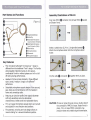
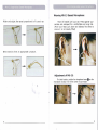
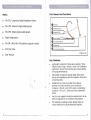
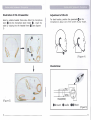
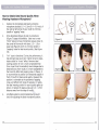
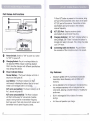
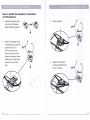
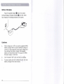
Parts:
•
MU-1FL:Targe sińqle-slded earset.
•
MU-1FM: Medium single-sided earset.
•
MU-1FS: Smali single-sided earset.
•
Foam Windscreen.
•
MU-3M: Ultra-mini rnicrophone capsule module.
•
Carrying Case.
•
User Manual.
______________________________________
1
Part Names And Functions
Assembly IlIustrations of MU-13:
0----------.
G------,
Plug male MMCi
and fasten firmlv.
(FigUre 1)
O eonnector
into female MMCX
e
socket
e
e
o
e
o
o Single-sided
o Cable Clip.
O
Earset.
o Detachable
Microphone
Input Connector (Female).
Microphone
Input Connector (Male).
. 4) Boom Holder.
O Microphone Boom.
O Gooseneck.
O Microphone Capsule.
o Detachable
8------"0..
O----~
O.
Select a suitable size (S, M or L) single-sided earset
Attach the microphone boom into the microphone boom
holder.
Key Features:
This innovative lightweight "enclosed ear " design is
different from the traditional "hook" design. The flexible
and pressable material ensures an ultra secure,
comfortable fit with or without glasses and will not fali
off during during performances.
Clip the cable
O and earset
e together
firmly in place.
Headworn frames comes standard. in three different
sizes ( smal(.J medium / large) to fit different
performers.
Detachable microphone capsule design allows secured,
easy hock-up and maintenance with the headworn
frame and connecting cable.
Featurlnq an ultra low-profile 3mm capsule diameter
wlth high sensitivity and omni-directional
characteristics. Sweat-proof and replaceable foarns.
CAUTION: ]f noise or signal drop-out occurs, double check if
the connection of MMCX is loose. Fasten firmly in
place, if it is. A loose MMCX connection may
produce noises and unstable signal transmission.
Thin vet rugged microphone capsule boom can be bent
and adjusted in any directions and positions.
The patented, swiveling ear hook design allows an
inward rotating for a secured directional position.
2
_
______________________________________
3
-
Wearing MU-l3 Earset Microphone:
Widen and adjust the earset proportional to fit user's ear.
Placethe earset over your ear. Press against your
earlobe and reshaped for a comfortable and snug feel.
(Move your head up & down and sideway few times to
ensure it is not loosely fitted)
Bent inward to form an appropriate curvature.
Adjustment of MU-l3:
G 50 the
For ideal location, positian the microphoneboom
microphoneis abaut 1cm ot the carner ot your mauth.
-4
_
______________________________________
5
Part Names And Functions
Parts:
•
MU-2FL: Large dual-sided headworn frame.
•
MU-1FM: Medium single-sided earset.
•
MU-1FS: Smali single-sided earset.
•
Foam Windscreen.
•
MU-3M: Ultra-mini microphone capsule module.
•
Carrying Case.
•
User Manual.
o
Earhook
~
Headset
Frame
~
Headset
Clip
e
e
Microphone
Boom Holder
Boom
fl) Gooseneck
$ Micro
hone Ca
sule
(Figure 2)
Key Features:
Lightweight, ergonomie frames are available in three
different sizes ( large / midium / smali) to fit different
performers. Secure fit around the ears prevent falling
off during performanees.
Detachable mierophone eapsule design allows easy
set-up and maintenance with the headworn frame and
eonneeting eable.
Available for an ultra law-profile 3mm eapsule
diameter with high sensitivity omni-direetional
eondenser ( MU-23 ) and lOmm sized uni-direetional
eondenser ( MU-210 ). Sweat-proof and replaeeable
foams.
'.
Very thin vet rugged mierophone eapsule boom ean be
bent and adjusted in any direetions and positians.
The patented, swiveling earhook design allows an
inward rotating for a seeure direetional position.
6
_
__
7
.. .... ....
....•
.
IIIustration of MU-23 Assemble:
Adjustment of MU-23:
Select a suitable headset frame size. Attach the microphone
boom ~ into the microphone boom holder
Insert the
cable by clipping into the headset frame ~ (see diagram
3)
ED .
1
For ideal locatio,n, 'position the gooseneck ~ 50 the
microphone is about lem of the corner of your mouth.
l
(Figure 4)
IIIustrations:
l
.I
(Figure 3)
OGround
8
_
__
GAudio
GO Short
(Figure 5)
9
(
How to Obtain Ideal Sound Quality When
Wearing Headworn Microphone?
1.
Position the microphone and boom so that the
microphone is about 1.0 ~ 1.5cm (004 ~ 0.6-inch) of
the right or left corner of your mouth to minimize
breath or "popping" noise.
2.
Omni-directional (Figure 6) and Uni-directianal
(Figure 7) types are available. Ideal way to wear
"Ornnl" type is to have microphone capsule closer to
the corner of the mouth with about 1.0 ~ 1.5cm
away (see Figure 8 and 9) to minimize breath or
"popping" noise for ideal sound quality. (See Figure
10).
3.
type is directional. During live performance, it
has stronger bass sound and higher dynamie range,
better suited for "musie" effect. However ideal
wearing position for Uni is more complicated than
Omni. Apart from the sensitivity level changes due to
distances away fram mouth, it is more susceptible to
the Proximity effect and popping noise. In theory, it
is recommended to position uni-directional capsule in
front of mouth for ideaI sound quality. However this
position is vulnerable to the problems of popping
noise, and affects both types af capsiJles. In reality,
the ideal wearing position for sound quality refers to
picture 11'(about 45 degree angle al'j.d 1.0 ~ 1.5cm
distance away from the edge of rnouth) ..
4.
Amplified system is recommended during sound
check for adjusting the ideal micraphane position.
10
"Uni"
11
..
..
•...
.
AGf-20T: Portable Mmiature Transmitter
Part Names And Functions
* When ACT button is pressed on the receiver, bring
ACT port of the transmitterwithin
30cm of the same
ACT (IR) port of the receiver. Transmitter will lock
automatically and synchronizes to the selected
receiver frequency.
ACT (IR) Port: Receives receiver signals
automatically to synchronize frequency.
Charging Indicator: Still "Red" indicates battery is
being charged; Still "Green" indicates the battery 15
charged and ready to be used. Fully charge may take
up to 3-4 hours.
•
MiPRO
Connecting Cable and Socket: Plug and fasten
the connector of the microphone boom into socket.
ACT·20T Transmit!er
Power Switch: Switch to "ON" to power on; switch
to "OFF" to power off.
Charging Socket: Plug in to recharge battery by
the attached MIPRO charger (switching adapter)
ONLY.Use other chargers with different specifications
may damage this device.
Power Indicator Status:
Key Features:
Normai Battery - The Power Indicator will lit for 1
second and then goes off.
Industry's lightest UHF PLL-synthesized switchable
transmitter. Works flawlessly with all MIPROACT
receivers.
.Low Batt~ry - The Power Indicator ;fili flash
continuously indicating the battery lęvel is low and
needs to be recharged within 10 minutes.
Can be attached to MU-23 headworn microphone for a
true wireless experience with no bodypack and no
wired cable, allowing complete freedom of mobility for
performers.
ACT syncs successfully: The Power Indicator will lit
for 1 second and goes off.
ACT syncs unsuccessfully: The Power Indicator
will flash continuously for 5-6 seconds. Possible
cause is wrong receiver or transmitter frequency
band was used. Check and ensure both receiver and
transmitter have te same frequency bands.
12
Built-in rechargeable lithium battery for money
savings.
6~8 Hours of operation per charge.
_
___________________________________
13
..
..
•...
ACT-20T: Portable Miniature Transmitter
How to Install the Headworn Transmitter
and Microphone:
1.
Unfasten the latch lock
by turning it sideway.
Open the latch upward.
2.
Place the headset frame
(middle section) into the
groove of ACT-20T
firmly (see picture).
Ensure the two roundshape microphone boom
holders are in the same
direction as the latch
lock.
14
_
3.
Close the latch.
4.
Fasten the hatch by
turning the hatch lock
firmly in place.
________________________________________
15
Battery Charging:
Plug the supplied charger ~ into an AC socket.
During charging, Charging indicator
turns red. When
fully charged, the Charging indicator turns green.
e
Cautions:
1.
When charging it is VITAL to use the supplied MIPRO
battery charger ONLYto avoid insufficient voltage or
current. Do not exceed the input supply voltage as it
may damage the battery charger, rechargeable
battery and transmitter itself. The output of MIPRO
DC power supply is 12V/O.2A.
2.
Turn the power "OFF" when ACT-20T is charging.
3.
To ensure safety DO NOT CHARGEthe ACT-20T with
battery chargers from other brands.
16
_