Download ANALOX 8000 – Helium Analyser User Manual


Transcript
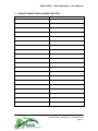
ANALOX 8000 – Helium Analyser
User Manual
Analox Sensor Technology Ltd
15 Ellerbeck Court, Stokesley Business Park
North Yorkshire, TS9 5PT
T: +44 (0)1642 711400 F: +44 (0)1642 713900
W: www.analox.net
E: info@analox.net
Analox 8000 – Helium Analyser – User Manual
LIST OF CONTENTS
1 Important Safety Warnings .......................................................................2
1.1
Electrical Shock Hazard Warning ......................................................2
2 Operating Instructions...............................................................................3
2.1
Introduction........................................................................................3
2.2
Operating Conditions.........................................................................4
2.3
Calibration .........................................................................................4
2.4
Alarm Operation ................................................................................5
2.5
Alarm Setting .....................................................................................5
2.6
Battery Backup (Option) ....................................................................6
2.7
Sensor Replacement .........................................................................6
2.8
Interference .......................................................................................7
2.9
Sensor Fault Indication ......................................................................7
2.10
Repair And Service............................................................................7
3 Installation.................................................................................................8
3.1
Rear Panel Connections....................................................................8
4 Specification ...........................................................................................10
4.1
Electrical ..........................................................................................10
4.2
Environmental..................................................................................11
4.3
Mechanical ......................................................................................11
5 Oxygen Sensor Replacement Record ....................................................12
6
Disposal .................................................................................................13
Document Ref: 8K0-810-07 – November 2010
Page 1
Analox 8000 – Helium Analyser – User Manual
1
IMPORTANT SAFETY WARNINGS
THIS PAGE SHOULD BE READ AND UNDERSTOOD BY ALL
PERSONNEL CONCERNED WITH THE INSTALLATION, OPERATION AND
MAINTENANCE OF THIS INSTRUMENT.
The 8000 Instrument is NOT suitable for operation in a Hazardous Area, as
defined by the British Standard BS 5345 Part 4.
1.1
Electrical Shock Hazard Warning
The electrical power used in the 8000 System may be at a voltage
sufficient to endanger life. Before carrying out any maintenance or
repair, ensure that the equipment is disconnected from any Mains
supply and tests made to ensure that isolation is complete.
Document Ref: 8K0-810-07 – November 2010
Page 2
Analox 8000 – Helium Analyser – User Manual
2
OPERATING INSTRUCTIONS
WARNING these instructions should be read and understood by all individuals
who will be responsible for operation of this Analyser. The actions taken as a
result of the measured levels must be in strict accordance with the Company
and Government Regulations.
2.1
Introduction
The Analox 8000 Helium Monitor provides a continuous digital display
of Helium concentration, in the gas flowing through the sensor unit.
The instrument displays the measured value on a 4 Digit red LED
display over the range 0.1 to 100%.
This is a dual resolution instrument, the resolution of the display may
be selected at any time, with a front panel switch, which effectively
suppresses the least significant digit without affecting the scaling of the
instrument.
The main sensor used in the monitor is a Helium thermal conductivity
sensor with microprocessor controlled linearization and temperature
compensation.
Further compensation is provided by an
electrochemical Oxygen sensor. This is to compensate for the helium
sensors small cross sensitivity to oxygen.
The instrument is easy to calibrate, using the ‘ZERO’, ‘CAL’ and ‘O2
CAL’ adjustments on the front panel. User adjustable high and low
audio/visual alarms, are fitted as standard and these may be adjusted
over the full range of the instrument. The optional relay outputs are
available on the instrument rear panel. A flowmeter and controlling
needle valve is mounted on the front panel of the monitor to control the
flow rate across the sensor unit.
Two power supply options are fitted on all instruments. Input 1 is a
standard IEC 3 pin connector for AC power in the range 85 to 264VAC,
47 to 63 Hz WITHOUT switching or selecting.
Input 2 is a standard co-axial battery charger type connector or a 2 way
screw terminal type connector for low voltage power input in the
following range:
12 to 32VDC.
Note the polarity of connection of DC is important.
If fitted, the monitor also incorporates a re-chargeable nickel cadmium
battery, which provides up to 1 hour of normal operation in the event of
Document Ref: 8K0-810-07 – November 2010
Page 3
Analox 8000 – Helium Analyser – User Manual
external power failure. External power status and internal battery
condition are indicated by an LED on the front panel.
2.2
Operating Conditions
The sample gas to be measured must meet the following conditions:
Flowrate:
Pressure:
NOTE:
20ltr/hour
+ 5psi Gauge (+ 350mbar Gauge)
IT IS IMPORTANT THAT THE SENSOR EXHAUSTS TO
ATMOSPHERIC PRESSURE. IF AN EXHAUST PIPE IS USED
FROM THE GAS OUT PORT ENSURE THAT IT IS NO
GREATER THAN 20 METRES IN LENGTH AND IS A
MIMIMUM OF 6mm IN DIAMETER. ALSO ENSURE THAT
THE PIPE HAS NO KINKS IN IT OR IS RESTRICTED IN ANY
WAY.
Under no circumstances should any other equipment or restriction be
connected to the exhaust port since any resultant back pressure will affect the
accuracy of the readings obtained.
2.3
Calibration
To ensure optimum performance, the instrument should have been
switched on for at least 2 Hours, before any calibration adjustments are
made. The following gases are required to calibrate the monitor:
•
•
•
100% Nitrogen
100% Helium
5 to 100% Oxygen with a helium balance (the higher the O2 content the
better)
To correctly calibrate the instrument the following steps must be carried
out in the order shown.
1) Zero Adjustment
Connect the 100% Nitrogen zero gas and adjust the flow rate to
approximately 20ltr/hr. Allow a few minutes for the reading to stabilise.
When steady, adjust the front panel ‘ZERO’ trimmer until the display reads
‘000.0’.
2) Span Adjustment
Connect the 100% Helium span gas and adjust the flow rate to
approximately 20ltr/hr. Allow a few minutes for the reading to stabilise.
When steady, adjust the ‘CAL’ trimmer until the display reads ‘100.0’.
Document Ref: 8K0-810-07 – November 2010
Page 4
Analox 8000 – Helium Analyser – User Manual
3) Oxygen Sensor Adjustment
Connect the Oxygen gas and adjust the flow rate to approximately 20ltr/hr.
Allow a few minutes for the reading to stabilise. When steady, adjust the
‘O2 CAL’ trimmer until the display reading matches the helium content of
the gas or where 100% O2 is used, the display reads ‘000.0’.
Note: when adjusting the ‘O2 CAL’ trimmer it is possible to put the
instrument in its error state, which is signified by the reading jumping rapidly
to an over range value. If no adjustment of the ‘O2 CAL’ trimmer will bring
the reading to the desired point repeat the first two steps of the calibration
procedure. If this doesn’t resolve the problem it is probable that the Oxygen
sensor needs replacing, contact your local distributor or Analox Sensor
Technology Ltd, for a replacement or further technical assistance.
2.4
Alarm Operation
If an alarm condition occurs, the internal audible buzzer will sound
intermittently and the yellow ‘HORN’ LED will flash, thereby identifying
which instrument is causing the alarm. The appropriate red ‘HI’ or ‘LO’
LED will indicate the alarm level. The audible alarm can then be
silenced by pressing the ‘MUTE’ button; this action will also turn off the
yellow ‘HORN’ LED. If the reading is still in an alarm condition, the red
‘HI’ or ‘LO’ LED will continue to flash until the helium concentration
returns within the normal band. The red LED will then turn off. If an
alarm condition occurs and the helium concentration then returns to
normal before the ‘MUTE’ button is pressed, then the audible and
visual alarms will continue to be active until the ‘MUTE’ button is
pressed. This facility allows the operator to be aware of any alarm
occurrence whilst the instrument was unattended.
The alarms have a built-in hysteresis of approximately 0.3% He to
overcome ‘nuisance’ triggering when measuring near the set points.
This means that if a high alarm occurs with a set point of 85.0%, then
having been acknowledged by pressing the MUTE button, the alarm
will not clear until the helium level drops below 84.7%.
2.5
Alarm Setting
Before any Adjustments are made to the ‘SET ALARM’ controls, the
operator should release the locks on the knobs. This is done by
moving the small lever located at the edge of the control until the knob
turns freely. After adjustment, the locks should be reset in order to
prevent accidental movement. The ‘SET HI’/‘SET LO’ toggle switch is
normally biased to its central position to read the measured He level.
The High alarm point is set by moving this switch upward and adjusting
the ‘SET HI ALARM’ control knob until the desired High alarm trip level
is displayed. The Low alarm trip point is set by moving the switch
downward and adjusting the ‘SET LO ALARM’ control knob until the
desired level is displayed. If the operator only wishes to check the
currently set alarm points this may be done by just pressing the ‘SET
Document Ref: 8K0-810-07 – November 2010
Page 5
Analox 8000 – Helium Analyser – User Manual
HI’/‘SET LO’ switch to the appropriate position, and reading the levels
on the LED Display.
2.6
Battery Backup (Option)
If the external power supply to the instrument fails, the power supply
circuitry in the instrument will automatically change over to the internal
battery. When the instrument is being driven by its internal battery, the
green ‘STANDBY’ LED on the front panel, will be lit and will remain on
until external power is restored. The internal battery will provide normal
operation for approximately 1 hour. When the battery has been
discharged to such a level that instrument operation below this level
would not be reliable, then a trip circuit will turn off the complete
instrument and indicate this state by flashing the green ‘STANDBY’
LED at approximately 1 second intervals.
2.7
Sensor Replacement
2.7.1 Oxygen Cell
When the instrument can no longer be calibrated by adjustment of the
‘O2 CAL’ control it is probable that the oxygen sensor capsule is
exhausted and should be replaced.
The sensors are push fit into a manifold on the rear panel of the
monitor. To replace the oxygen sensor, switch off the instrument and
remove the Oxygen sensor by pulling it out of the sensor manifold. Fit
the new sensor and then switch the monitor on. The new sensor will
require a period of approximately 1 hour to settle, after which the
instrument should then be calibrated.
The Oxygen Sensor Assembly has a life of approximately 2 years in
normal air but this will be reduced if it is constantly exposed to higher
concentrations of Oxygen. Conversely, if the sensor is normally
exposed to lower concentrations of Oxygen, its life may be extended.
The sensor must be replaced with an Analox Oxygen sensor type
9100-9212-94P, as this sensor is especially manufactured for this
instrument.
There are no serviceable parts in the sensor and cable assembly - the
entire unit must be replaced.
Warning
The sensor in the Analox 8000 is an electrochemical device and
contains a caustic electrolyte. Always check to make sure that it is not
leaking and do not allow it onto any part of your body or clothing. In the
event that you do come into contact with the electrolyte wash the
contaminated part with copious amounts of water.
Document Ref: 8K0-810-07 – November 2010
Page 6
Analox 8000 – Helium Analyser – User Manual
WARNING
If after handling the sensor your fingers or other parts of your
body feel slippery or stings wash with a lot of water.
If stinging persists get medical attention!
2.7.2 Helium Sensor
The Helium sensor is not a consumable part and, if maintained, stored
and used correctly, should last the life of the instrument. If the sensor
does need replacing, maybe due to water damage, this can only be
carried out by Analox and the Analox 8000 needs to be returned.
2.8 Interference
Whilst all reasonable precautions have been taken within the
Instrument circuitry and the case is RF screened, it is still possible, in
common with other instruments, that very strong, local Radio
Frequency fields could cause interference. This will show up as erratic
readings on the LED Display. Where possible, RF sources such as
Portable Radio Transmitters or Telephones should not be operated
very close to the instrument.
2.9 Sensor Fault Indication
Sensor faults and extreme over range states are indicated by the
display reading a greatly over range value (>110%). If the monitor is in
this fault state, try and perform the calibration procedure. If the first two
calibration gases create no change in the display reading, try adjusting
the ‘O2 CAL’ trimmer until the reading returns to between 0.1 and
100%. If this is successful try to perform the full calibration procedure
again. If the fault state persists contact your local distributor or Analox
Sensor Technology Ltd for further assistance.
2.10 Repair and Service
Apart from periodic recalibration, the Instrument has been designed to
provide long, trouble-free service. However, in the event of a fault
condition arising, contact your local distributor or Analox Sensor
Technology Ltd. The Instrument contains complex, precision circuitry
which requires special test equipment to ensure correct internal set-up
and calibration. Internal repairs or adjustments by the user are
therefore NOT recommended.
A separate technical manual is
available for approved service centres, from Analox Sensor Technology
Ltd.
Document Ref: 8K0-810-07 – November 2010
Page 7
Analox 8000 – Helium Analyser – User Manual
3
INSTALLATION
The Analox 8000 Monitors are available in two forms:
1) Suitable for insertion in a 19 inch rack frame
2) Suitable for direct mounting in an existing instrument panel
For details of dimensions, cut outs and mounting centres, refer to the
mechanical specifications at the end of this handbook. The frame mounting
version should be inserted in a suitable rack and secured by the 4 corner
screws and bushes, supplied with the instrument. Refer to the connection
details below. When fitting the panel mounting instrument, the screws and
bushes should be left attached to the instrument, as supplied and the whole
assembly inserted into the panel, easing the bushes into the 10mm holes.
Tightening the 4 screws will expand the bushes, locking them into the panel.
If the instrument is subsequently removed from the panel, it is only
necessary to remove the screws – the bushes should remain captive in the
panel.
3.1
Rear Panel Connections
All Electrical inputs to and outputs from the Instrument are connected
via various sockets and terminals on the rear panel of the Instrument.
All connections are identified by labels on the rear panel but are
repeated here for convenience.
Power Supply
Power for the instrument may be derived from 1 of 2 options:
1) AC power in the range 85 to 264VAC, 47 to 63 Hz and connected via a
standard IEC 3 pin plug/socket. A suitable lead is supplied with the
instrument. Note that NO voltage selection is required when using this
input – the instrument will operate from any voltage within the stated
range. The fuse for this power input is mounted in the rear panel and is
rated at 1 Amp ‘T’ type.
2) Low voltage DC in the range 12 to 32V with a ripple not exceeding 1
volt and connected via the battery charger type connector or the 2 way
screw terminal type connector. THE LOW VOLTAGE DC SUPPLY
SHOULD BE EXTERNALLY FUSED at a rating of 1 Amp using a ‘T’
type delay fuse. Note that connection polarity is important when using
the DC input.
Signal Outputs (Option)
All signal outputs are made to removable, screw terminal plugs. The main
connector is located down the right side of the rear panel, when viewed from
the rear.
Document Ref: 8K0-810-07 – November 2010
Page 8
Analox 8000 – Helium Analyser – User Manual
IMPORTANT: PINS 15 AND 16 SHOULD BE LINKED TOGETHER.
Two Analogue outputs, proportional to the measured input signal are available
from the Instrument. Pin 8 provides 0-1 Volt representing 0 to Full scale and
Pin 9 provides a 4-20mA current output representing 0 to full scale. Pin 7 is
the Common connection for both outputs. The Voltage output must NOT be
connected to a load less than 10,000 Ohms. The Current output is powered
from an internal nominal 24 Volt supply and can operate into a load from 50
Ohms to 500 Ohms.
Alarm Relays (Option)
The Analox 8000 can be fitted with two relays which operate in conjunction
with the HI and LO alarms. The relays have a single pole changeover contact
arrangement, rated to switch up to 7 Amps @ 240VAC or 30VDC. The relays
may be configured to be energised or de-energised, when the Instrument is in
a non-alarm state. If the relays are configured to be in a normally energised
state, this will provide a ‘Fail-Safe’ facility in that a total power failure will
cause the relays to release and signal an alarm condition. Contact
arrangement is shown on the rear panel. Instruments normally leave the
factory with the relays configured to ENERGISE IN ALARM conditions. The
‘COM’ and ‘NO’ contacts will close, in an alarm condition.
Document Ref: 8K0-810-07 – November 2010
Page 9
Analox 8000 – Helium Analyser – User Manual
4
SPECIFICATION
4.1 ELECTRICAL
Range
Sensor Type
Sensor Life
Accuracy
Response Time
Warm up Time
Gas Flow Rate
Display
Power Supply
Outputs
Alarm Relays
(Optional)
Optional Extras
0.1-100% He
Helium
Thermal
Conductivity
sensor
with
microprocessor linearization, temp and O2 cross
sensitivity compensation.
Oxygen sensor - Electrochemical Cell.
Helium - up to 10 years (12 month warranty)
Oxygen - up to 2 years in air (24 month graded warranty)
±0.5% of Full Scale at Standard Temperature and
Pressure
15 Seconds to T90
<15 Seconds
20ltr/hr
4 Digit High-Brightness Red LED
85 to 264VAC, 47 to 63 Hz
12 to 32VDC
0 – 1Volt (minimum load 10K ohms)
4 – 20mA Internally powered (optional)
2 x Single Pole changeover, configurable to be
energised or de-energised when not in alarm state
Rated at 7A 240Vac or 30Vdc
1 Hour Battery Backup
Document Ref: 8K0-810-07 – November 2010
Page 10
Analox 8000 – Helium Analyser – User Manual
4.2 ENVIRONMENTAL
Operating
0 to +50oC
Temperature
Storage Temperature -5 to +50oC
Relative Humidity
95% at 40oC Non Condensing
Operating Pressure
Atmospheric pressure ±350mbar (±5psi)
4.3 MECHANICAL
Dimensions
Depth Overall 235mm
Rack Mount Version Depth behind Panel 300mm (min)
Height Overall 129mm (3U)
Width Overall 212mm (1/2 Rack)
Dimensions
Depth Overall 235mm
Panel Mount Version Depth behind panel 300mm (min)
Height Overall 133mm
Width Overall 240mm
Weight
Weight 2.5 Kg
Panel Cut-out
Height 112.5mm
Width 221mm
Mounting Centres
4 x 10mm Holes
Height 122.5mm
Width 211.4mm
Centred on Cut-out
Document Ref: 8K0-810-07 – November 2010
Page 11
Analox 8000 – Helium Analyser – User Manual
5
OXYGEN SENSOR REPLACEMENT RECORD
Serial Number
In Service Date
Document Ref: 8K0-810-07 – November 2010
Page 12
Analox 8000 – Helium Analyser – User Manual
6
DISPOSAL
According to WEEE regulation this electronic product can not be placed in
household waste bins. Please check local regulations for information on the
disposal of electronic products in your area.
Document Ref: 8K0-810-07 – November 2010
Page 13