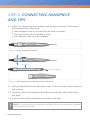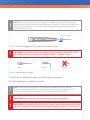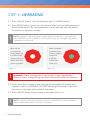
1
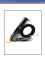
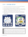
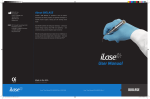
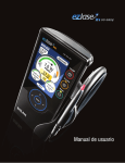
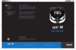
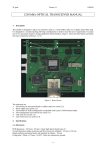
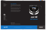
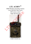
© 2009 Biolase Technology, Incorporated. All Rights Reserved.
BIOLASE ezlase™ Quick Reference Guide.
BIOLASE, the BIOLASE logo, ezlase™, the ezlase™ logo are either registered trademarks
or trademarks of BIOLASE Incorporated in the United States and/or other countries.
From
An Exclusive
Partner of
waterlasedentistry.com Toll-free 888-424-6527
biolase.com
NASDAQ: BLTI
USA
Germany
Australia
New Zealand
Biolase Headquarters
4 Cromwell
Irvine, CA 92618
T 949 361 1200
F 949 273 6687
Biolase Europe GmbH
Paintweg 10
92685 Floss, Germany
T 49 9603 8080
F 49 9603 2360
Biolase Australia Pty. Ltd.
26 Wakeham Street
Adelaide, South Australia 5000
T +61 8 8227 1780
F +61 8 8232 9241
ABN 116 912 353
Biolase NZ Ltd.
P.O. Box 302628,North-Harbour
Auckland 1330, New Zealand
T +64 9 479 6215
F +64 9 479 6216
ABN 1737441
P/N 5400046 Rev. E (2/2009)
Quick Reference Guide
Soft Tissue Diode
INDEX
Warnings. . . . . . . . . . . . . . . . . . . . . . . . . . . . . . . . . . . . . . . . 2
Equipment Description. . . . . . . . . . . . . . . . . . . . . . . . . . . . 3
Step 1: System Setup . . . . . . . . . . . . . . . . . . . . . . . . . . . . . 5
Step 2: Connecting Handpiece and Tips. . . . . . . . . . . . . . 7
Step 3: Operating. . . . . . . . . . . . . . . . . . . . . . . . . . . . . . . . . 9
Step 4: ezlase™ Specifications . . . . . . . . . . . . . . . . . . . . . 10
1
5400046 REV. E (02/11/09)
WARNINGS
s
Make sure distal end of the handpiece is protected from contamination with
tip plug when laser is not in use. If window at the fiber shaft is dirty, disconnect
handpiece and clean window with cotton swab moistened with alcohol.
s
DO NOT touch the input end of the tip.
s
STOP immediately if handpiece or tip canula is hot. Replace tip.
s
STOP immediately if you see tip ferrule glowing yellow, not red.
Replace the window.
s
DO NOT operate if aiming beam is not present at distal end of the tip.
s
DO NOT use 200 μm tip with power set above 3.0 Watts.
s
To ensure proper wireless communication, always power up unit
with the footswitch cable connected (See Step 1).
!
caution: Federal law restricts this device to sale by or under the order of
a dentist or physician or other licensed practitioner.
2
Equipment Descriptions
Emergency Stop
Power Switch
Power Connector
Stand
3
5400046 REV. E (02/11/09)
Service Connector
Remote
Interlock
Connector
Footswitch
Connector
Fiber Spool
Fiber
4
STEP 1: SYSTEM SETUP
1.1 Connect power cord to power connector on the unit and plug into wall outlet;
1.2 Connect footswitch cable to the unit and to the footswitch;
1.3 Turn power switch to ON position. Welcome to ezlase™ screen will be displayed.
1.4 Enter the three digit key access code using the touch screen or Navigation wheel
(right arrow “>” and Enter buttons). Access Key Code is 123;
1.5 System will go to the Main Menu. If code is entered wrong, reenter the code;
1.6 Disconnect and press the footswitch, it is now programmed to communicate
with the system.
BIOLASE
Welcome to
1
2
3
4
5
6
7
8
[ Figure 1 ] Welcome Screen.
!
5
[ Figure 2 ] Main Menu.
Note: Charge footswitch battery for 4 hours when first connected. Power
switch should be ON. Before disconnecting the footswitch cord after each
charging, re-cycle power by turning power switch OFF and ON to re-set
wireless communication. Then unplug footswitch cord from the unit and from
the footswitch. Press the footswitch – blinking blue LEDs confirm presence of
wireless communication. Footswitch will operate for about 1 week without
re-charge, so long as power switch is maintained in the “ON” position.
5400046 REV. E (02/11/09)
FRONT PANEL [ Figure A ]
# Item
Item Description
1
Turns the controls and display on and off.
ON/OFF 2 READY Allows energy delivery when footswitch is pressed.
3 READY LED Indicates unit is in READY mode.
4 STANDBY Does not allow energy delivery.
5 STANDBY LED Indicates unit is in STANDBY mode.
6
EMISSION LED
Indicates emitting of the laser power.
7
WIRELESS ON
Indicates communication with footswitch.
8
NAVIGATION WHEEL
Allows to select functions and adjust parameters.
6
5
1
7
1
5
4
3
2
3
2
9
6
8
7
8
4
[ Figure A ]
[ Figure B ]
MAIN MENU [ Figure B ]
# Item
Item Description
1
Indicates average power delivered.
AVERAGE POWER DISPLAY
2 MAXIMUM POWER DISPLAY Indicates maximum allowable delivered power.
3 POWER (up/down) 4
MENU
Allows adjustment of delivered optical power.
Selects user function.
5 PROCEDURES Selects pre-set procedure parameters.
6 PULSE LENGTH (up/down) Allows adjustment of laser ON time.
7 PULSE INTERVAL (up/down) Allows adjustment of laser OFF time.
8 LASER MODE Allows switching and indicates laser operation
mode (continuous or pulsed).
9 ENERGY DISPLAY Allows setting and displays amount of laser
energy that has been delivered or to be delivered.
6
STEP 2: CONNECTING HANDPIECE
AND TIPS
2.1 e
zlase™ is shipped with the handpiece and tip plug connected. To disconnect
the handpiece from Fiber Shaft:
s
Take handpiece body in one hand and the shaft in another;
s
Push two buttons on the handpiece shaft;
s
Pull handpiece with the ring to separate.
[ Figure 3 ] ezlase™ Handpiece Assembly
Fiber Shaft
Protective Window
Handpiece
[ Figure 4 ] Disconnecting the Handpiece (push both buttons)
2.2 Verify visually that Protective Window is clean. If not, use cotton swab moistened
with alcohol;
2.3 Carefully connect the Handpiece by sliding it over the fiber shaft until it clicks
into place;
2.4 Insert the selected tip and tighten it clockwise until snug.
!
7
Note: To ensure proper operation, regularly check the protective window
and clean it if necessary.
5400046 REV. E (02/11/09)
!
Note: The tips for ezlase™ are fingers-bendable single-use accessories,
which are provided in three core diameters: 200 μm, 300 μm and 400 μm
and different lengths. Tips are intended for single-use only and must be
sterilized prior to use.
Tip Assembly
[ Figure 5 ] Disconnecting the fiber Tip (twist first counter clockwise)
!
Caution: Do not bend tips with sharp angle – it will break the tip. If the
red aiming beam is not present in READY mode – replace the tip.
Bend
Right
Wrong
[ Figure 6 ] Bending the tip canula.
2.5 Wind excess fiber optic cable on to fiber spool (clockwise).
2.6 Place handpiece in handpiece holder.
!
note: The fiber optic cable is permanently attached to the ezlase™
Console. The Handpiece is a reusable accessory. The Handpiece will
require cleaning and sterilization after each patient treatment.
!
Caution: Never operate the laser without a fiber tip attached.
!
Caution: All persons present in the operatory must wear appropriate laser
eyewear protection for the diode laser wavelength of 940±nm, 810±15nm.
8
STEP 3: OPERATING
3.1 Press ON/OFF button. The unit will power up in a STANDBY mode.
3.2 Press READY button. System fan will start and after 2 second delay aiming red
beam will be turned ON. Laser parameters can be selected from the pre-set
Procedures or adjusted manually.
!
note: Unit will only emit laser energy when footswitch is pressed and
set to READY mode. In READY mode, values may be changed only when
footswitch is released.
When the tip
is straight, the
aiming beam will
look like a circle,
outlining the area
where main laser
power is applied.
[ Figure 7 ]
!
When footswitch
is pressed, laser
power is applied
and beam
will fill the
middle area
of the spot.
[ Figure 8 ]
Warning: When aiming beam is not present or has a significantly
different shape, change the tip and inspect/clean the protective window.
3.3 At this point laser is ready to use, pressing the footswitch will activate laser
radiation. Refer to EQUIPMENT DESCRIPTION for guide through main menu
functions or User Manual for detailed explanation.
3.4 Press ON/OFF button to go to sleep mode when not in use.
!
9
note: System will automatically go first to STANDBY mode and then to
sleep mode when not in use for 15 minutes.
5400046 REV. E (02/11/09)
STEP 4: ezlase™ SPECIFICATIONS
General
W x H x D (3.5” x 7.0” x 2.5”) (8.5 x 18 x 6cm)
Weight
2 lbs. (1.0 kg)
s
Dimensions
s
Electrical
100 to 240 ~ at 2A
Frequency
50 / 60 Hz
External Fuses
None
Main Control
Power Switch
On / Off Controls
Keypad Button, Emergency Stop
Remote Interruption
Remote Interlock Connector
s
Operating Voltage
s
s
s
s
s
Laser
IV (4)
Medium
GaAlAs, InGaAsP
Wavelength
810 ± 15 nm or 940 ± 15 nm
Max Output Power
7 Watts @ 940nm, 4.5 Watts @ 810nm
Power Accuracy
± 20%
Power Modes
Continuous, Pulse Modulation
Pulse Length*
0.06 ms - 10 sec
Pulse Interval*
0.06 ms - 10 sec
s
Laser Classification
s
s
s
s
s
s
s
s
Pulse Repetition Rate up to 10 KHz (for reference)
200, 300, 400 µm
NOHD
11.8 meters
Beam Divergence
8-22 degrees per side angle
Fiber Cable Length
5 feet (1.524 meters)
s
Fiber Tips Diameter
s
s
s
Other Light sources
s
Aiming Beam
* The following ComfortPulse® length
and interval settings will result in the
ranges specified:
Laser Diode, max 3 mW, 630-670nm, class 3B
Display
Range
0.05 ms
0.10 ms
0.20 ms
0.05 ms – 0.07 ms
0.10 ms – 0.14 ms
0.20 ms – 0.28 ms
10