Download Packet Telecommand Decoder with AMBA AHB Interface


Transcript
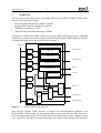
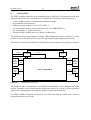
Packet Telecommand Decoder with AMBA AHB Interface
(PDEC3AMBA)
Data Sheet
SCTMTC-002-01
Version 0
October 2003
Prepared by Sandi Habinc
Stora Nygatan 13
411 08 Göteborg
Sweden
tel +46 31 802405
fax +46 31 802407
www.gaisler.com
SCTMTC-002-01
1
INTRODUCTION
1.1
Scope
2
This document describes the Packet Telecommand Decoder with AMBA AHB Interface
(PDEC3AMBA) synthesizable VHDL model. The objective is to describe the model at a level
of detail allowing its integration into an overall system. It is not the objective to describe the
model to a level of detail allowing modifications or usage of individual modules in the model
hierarchy.
The PDEC3AMBA model has been developed within the Highly Integrated Control and Data
System (HICDS) activity. It is based on the Packet Telecommand Decoder (PDEC3) module,
the External CPDU Interface Module (ExtCpduIf), the CPDM Selector Module (CSEL) and the
Command Pulse Distribution Module (CPDM), all developed by Saab Ericsson Space and used
in the Single Chip Telemetry and Telecommand (SCTMTC) ASIC developed in the HICDS
activity.
1.2
Introduction
The purpose of the Packet Telecommand Decoder with AMBA AHB Interface (PDEC3AMBA)
synthesizable VHDL model is to provide the user with a single module implementing CCSDS/
ESA compatible telecommand decoder and command pulse distribution unit with an AMBA
Advanced High-performance Bus (AHB) interface.
1.3
How to read this document
Not to duplicate information already available elsewhere, this document makes use of extensive
references to the SCTMTC ASIC User’s Manual (AD2) in which the various module functions
are described in detail. Only newly introduced information or deviations are reported in this
document.
1.4
Disclaimer
The responsibility of Gaisler Research for the Packet Telecommand Decoder with AMBA AHB
Interface (PDEC3AMBA) synthesizable VHDL model is limited to the AMBA AHB
adaptation. The responsibility for the embedded modules remains with Saab Ericsson Space.
1.5
Constraints
Although the embedded modules can be configured according to user needs, the configuration
of the PDEC3AMBA model has been constrained to the module configurations used in the
SCTMTC ASIC. In this way the basic telecommand decoder functionality of the module VHDL
models as used in PDEC3AMBA has already been validated in the HICDS activity, not
requiring any further validation.
SCTMTC-002-01
3
1.6
Applicable documents
AD1
AMBATM Specification, Rev 2.0, ARM IHI 0011A, 13 May 1999, Issue A, first
release, ARM Limited
SCTMTC ASIC User's Manual, P-ASIC-NOT-00122-SE, Issue 6, September 2003,
Saab Ericsson Space, Sweden
AD2
1.7
Applicable VHDL source code
AD3
AD5
SCTMTC ASIC synthesizable VHDL Model, delivered on 9 September 2003, Saab
Ericsson Space, sctmtc.tar.gz
Packet Telecommand Decoder with AMBA AHB Interface (PDEC3AMBA)
synthesizable VHDL model, version 0.1, Nov. 2003, pdec3amba.vhd
AMBA synthesizable VHDL package, version 0.5, February 2002, amba.vhd
1.8
Reference documents
RD1
RD2
RD3
ESA VHDL Modelling Guidelines, ASIC/001, Issue 1, September 1994
IEEE Standard VHDL Language Reference Manual, IEEE Std 1076-1993
IEEE Standard Multivalue Logic System for VHDL Model Interoperability
(Std_Logic_1164), IEEE Std 1164-1993
IEEE Standards Interpretations: IEEE Standard VHDL Language Reference Manual,
IEEE Std 1076/INT-1991
AD4
RD4
1.9
Related documents
The applicable and reference documents related to the embedded modules are described in
sections 3.1 and 3.2 in AD2, respectively.
1.10
AHB
AMBA
ESA
HICDS
PW
VHDL
VHSIC
Acronyms and abbreviations
Advanced High-performance Bus (AMBA interface)
Advanced Microcontroller Bus Architecture TM
European Space Agency
Highly Integrated Control and Data System
PacketWire
VHSIC Hardware Description Language
Very High Speed Integrated Circuits
SCTMTC-002-01
4
2
CONVENTIONS
2.1
Advanced Microcontroller Bus Architecture
Convention according to the Advanced Microcontroller Bus Architecture (AMBA)
Specification, AD1, applying to the AHB and APB interfaces:
• Signal and port names are in upper case, except for the following:
• A lower case 'n' in the name indicates that the signal or port is active low.
• Constant names are in upper case.
• The least significant bit of an array is located to the right, carrying index number zero.
AMBA n-bit field
most significant
n-1
Table 1:
2.2
least significant
n-2 down to 1
0
AMBA n-bit field definition
Consultative Committee for Space Data Systems
Convention according to the Consultative Committee for Space Data Systems (CCSDS)
recommendations, applying to all relevant structures:
• The most significant bit of an array is located to the left, carrying index number zero, and is
transmitted first.
• An octet comprises eight bits.
General convention, applying to signals, ports and interfaces:
• Signal or port names are in mixed case.
• An upper case '_N' suffix in the name indicates that the signal or port is active low.
CCSDS n-bit field
most significant
0
Table 2:
2.3
least significant
1 to n-2
n-1
CCSDS n-bit field definition
Data structures
Data structures specific to the embedded modules are described in sections 4.9.3 and 4.9.6 in
AD2.
2.4
Waveform formats
Waveform formats specific to the embedded modules are described in sections 7.3.1.2, 7.3.2,
7.4.1 and 7.6.2 in AD2.
SCTMTC-002-01
3
5
OVERVIEW
The Packet Telecommand Decoder with AMBA AHB Interface (PDEC3AMBA) VHDL model
comprises the following modules:
• Packet Telecommand Decoder (PDEC3) Module
• External CPDU Interface Module (ExtCpduIf)
• CPDM Selector Module (CSEL)
• Command Pulse Distribution Module (CPDM)
The purpose of the PDEC3AMBA model is to provide AMBA AHB interface to the embedded
modules, converting between the proprietary internal PI-bus and the AMBA AHB specification.
A simple block diagram of the model is shown in figure 1.
AMBA AHB
PDEC3AMBA
PDEC3
Transponder I/F
PI2AHB
Coding Layer
PI2AHB
Transfer Layer
Configuration I/F
PI2AHB
Authentication Layer
PI2AHB
Segmentation Layer
MAP I/F
CLCW I/F
Telemetry Reporting
AHB2PI
MAP 0
TC request
MAP 6
TcOnly
PI2AHB
CPDU I/F
CPDM
PM request
RM
request
External
CPDU
I/F
PI2AHB
Figure 1:
CSEL
CPDM
request
CSEL Status I/F
External CPDU I/F
PDEC3AMBA block diagram
Note that the External CPDU Interface is acting as the Reconfiguration Module in the
PDEC3AMBA VHDL model. It is thus not possible to connect the External CPDU Interface to
the Telecommand input of the CSEL module. More detailed information can be found in section
5.4.1.5.4 in AD2. All CSEL external ports are thus only related to the External CPDU Interface.
SCTMTC-002-01
4
6
DESCRIPTION
Not to duplicate information already available, this document makes use of extensive references
to the SCTMTC ASIC User’s Manual (AD2) in which various module functions are described
in detail. Only newly introduced information or deviations are reported herein.
4.1
Functionality
The functionality of the embedded modules is described in sections 5.4.3, 5.4.4, 5.4.5, and 5.4.6
in AD2.
4.2
Software interface
The software interface of the embedded modules is described in sections 6.3, 6.4, 6.5, and 6.6
in AD2. The register definition summary related to the embedded modules is described in
sections 6.10, 6.10.3, 6.10.4, 6.10.5, and 6.10.6 in AD2.
The memory usage and mapping of the embedded modules is described in section 6.11.3 in
AD2. The overall memory map for the embedded modules is described in section 5.4.2.2 in
AD2.
4.3
Hardware interface (external)
The hardware interface of the embedded modules is described in sections 7.3, 7.4, 7.5, and 7.6
in AD2.
4.4
AMBA AHB slave interface (internal)
All registers of the embedded modules are accesses via a single AMBA AHB slave interface of
the PDEC3AMBA VHDL model.
The AMBA AHB slave interface has been reduced in functionality to support only what is
required. The following features are constrained:
• only supports HSIZE = HSIZE_WORD, HRESP_ERROR generated otherwise
• only supports HMASTLOCK = 0b, HRESP_ERROR generated otherwise
• no HBURST decoding, bursts are thus supported
• no HPROT decoding
• neither HRESP_HSPLIT nor No HRESP_HRETRY generated
• only big-endianness is supported
• HRESP_ERROR is generated on:
•
address outside decoded register areas
•
error response from module
•
ready response not generated from module within 16 HCLK cycles.
• HADDR(1 downto 0) not checked
• specific address decoding for four register modules:
•
HADDR(15 downto 10) = module select
•
HADDR(9 downto 2) = module register address
• complete address decoding is not performed, for compatibility with AD2 the register space
should be decoded accordingly by an external AMBA AHB arbiter / decoder
• access to protected registers can only be done when the HSUPERUSER port is asserted
SCTMTC-002-01
4.5
7
AMBA AHB master interface (internal)
Each AMBA AHB master interface has been reduced in functionality to support only what is
required for the PDEC3AMBA model. One AMBA AHB master interface is provided for each
PI-bus DMA channel. The following AMBA AHB master interface features are constrained:
• only generates HSIZE = HSIZE_BYTE, HSIZE_HALFWORD and HSIZE_WORD
• only generates HLOCK = 0b
• only generates HPROT = 0000b
• only generates HBURST = HBURST_SINGLE
• never generates HTRANS = HTRANS_BUSY
• generates the following responses to the embedded modules:
•
HRESP = HRESP_OKAY, ends access with ready
•
HRESP = HRESP_ERROR, ends access with error
•
HRESP = HRESP_RETRY, access is rescheduled till ready or error
•
HRESP = HRESP_SPLIT, access is rescheduled till ready or error
• only big-endianness is supported, but:
•
a byte is always mapped on data bits (7 downto 0) on PI-bus side, and
•
a halfword is always mapped on data bits (15 downto 0) on PI-bus side
• only two outstanding acknowledgments allowed on PI-bus side
•
•
•
•
PI-bus lock is not supported
PI-bus bursts are not supported
PI-bus flush is unused
PI-bus page is not supported.
Note that the performance of the interface is limited due to the fact that the PI-bus interface
requires that input signals are driven directly from a flip-flop at the source.
Throughput:
Latency:
Pipeline:
Sustained transfer rate is one access in 2 HCLK periods at zero AMB AHB
waitstates.
From PI-bus DmaReq asserted to PI-bus DmaRdy sampled: 4 to 5 HCLK
periods at zero AMB AHB waitstates.
Only one PI-bus access is handled at a time, to provide for automatic error
handling and retry.
The PDEC3AMBA module can act as a default AHB master generating idle accesses when
required. It only implements a single word access at a time, without bursts, to reduce complexity
for retry and split handling, and not requiring the 1024 byte boundary imposed by the AMBA
specification on burst transfers to be taken into account.
SCTMTC-002-01
4.6
8
Design aspects
The PDEC3AMBA model is a fully synchronous design based on a single system clock strategy.
Registers in the model are reset asynchronously or synchronously. The reset input can be
asserted asynchronously, but requires synchronous de-assertion to avoid any recovery time
violations. The width of the asserted pulse of the HRESETn input signal should be at least one
HCLK clock period.
The priority, latency and throughput requirements of the six AMBA AHB master interfaces of
the PDEC3AMBA model are listed in table 3.
Priority
Interface name
Latency and Throughput
1 = highest
2
AHBMSibWr
AHBMSlrb
one access for every 16 telecommand input bits
one access for every 16 MAP interface output bits
3
4
5
6 = lowest
AHBMAub
AHBMCpdu
AHBMExtCpdu
AHBMSibRd
368+1024 accesses for every 192 telecommand input bits
two accesses for each pulse command duration
one access for every 16 input bits
eight accesses for every 192 telecommand input bits
Table 3:
Priority and latency requirements
The interrupt signals AHBSIrq_PDEC3, AHBSIrq_CSEL and AHBSIrq_CPDM are asserted
for one HCLK clock period when an interrupt occurs.
SCTMTC-002-01
5
9
INTERFACES
The Packet Telecommand Decoder with AMBA AHB Interface (PDEC3AMBA) VHDL model
interfaces are listed in table 4 and described in the subsequent sections.
Name
Type
Mode
Description
Remark
System interface
HRESETn
Std_ULogic
in
Asynchronous reset
HCLK
Std_ULogic
in
System clock
HSUPERUSER
Std_ULogic
in
Super-user enable
AMBA AHB Slave interface
AHBSIn
AHB_Slv_In_Type
in
AMBA AHB slave input
AHBSOut
AHB_Slv_Out_Type
out
AMBA AHB slave output
AHBSIrq_PDEC3
Std_ULogic
out
Pending interrupt
PDEC3
AHBSIrq_CSEL
Std_ULogic
out
Pending interrupt
CSEL
AHBSIrq_CPDM
Std_ULogic
out
Pending interrupt
CPDM
AMBA AHB Master interface - Serial Input block
AHBMSibWrIn
AHB_Mst_In_Type
in
AMBA AHB master input PDEC3
AHBSMibWrOut
AHB_Mst_Out_Type
out
AMBA AHB master output
AMBA AHB Master interface - Segmentation Layer and Router block
AHBMSlrbIn
AHB_Mst_In_Type
in
AMBA AHB master input PDEC3
AHBMSlrbOut
AHB_Mst_Out_Type
out
AMBA AHB master output
AMBA AHB Master interface- Authentication block
AHBMAubIn
AHB_Mst_In_Type
in
AMBA AHB master input PDEC3
AHBMAubOut
AHB_Mst_Out_Type
out
AMBA AHB master output
in
AMBA AHB master input ExtCpduIf
out
AMBA AHB master output
AMBA AHB Master interface - External CPDU Interface
AHBMExtCpduIn
AHB_Mst_In_Type
AHBMExtCpduOut AHB_Mst_Out_Type
AMBA AHB Master interface - Command Pulse Distribution Unit
AHBMCpduIn
AHB_Mst_In_Type
in
AMBA AHB master input CPDM
AHBMCpduOut
AHB_Mst_Out_Type
out
AMBA AHB master output
AMBA AHB Master interface - Serial Input block
AHBMSibRdIn
AHB_Mst_In_Type
in
AMBA AHB master input PDEC3
AHBMSibRdOut
AHB_Mst_Out_Type
out
AMBA AHB master output
Table 4:
PDEC3AMBA interfaces
SCTMTC-002-01
10
Name
Type
Mode
Description
Packet Telecommand Decoder (PDEC3)
PdecTcAct
Std_ULogic_Vector(5 downto 0)
in
Channel Active
PdecTcClk
Std_ULogic_Vector(5 downto 0)
in
Channel clock
PdecTcIn
Std_ULogic_Vector(5 downto 0)
in
Channel data
PdecRfAv_N
Std_ULogic_Vector(3 downto 0)
in
RF Available
PdecTcPrior
Std_ULogic
in
Priority mode
PdecTcDyn
Std_ULogic
in
Dynamic mode
PdecAuEnable
Std_ULogic
in
AU enabled
PdecMapAdt
Std_ULogic
out
MAP aborted
PdecMapClk
Std_ULogic
out
MAP clock
PdecMapData
Std_ULogic
out
MAP data
PdecMapDsrG
Std_ULogic
out
Sender ready
PdecMapDtrG
Std_ULogic
in
Receiver ready
PdecMapDsr
Std_ULogic_Vector(5 downto 1)
out
Sender ready
PdecMapDtr
Std_ULogic_Vector(5 downto 1)
in
Receiver ready
PdecMapGenA
Std_ULogic_Vector(5 downto 0)
out
Address
PdecClcwClk
Std_ULogic_Vector(1 downto 0)
in
CLCW clock
PdecClcwSamp
Std_ULogic_Vector(1 downto 0)
in
CLCW control
PdecClcwD
Std_ULogic_Vector(1 downto 0)
out
CLCW data
PdecMapSwitch
Std_ULogic
in
MAP switch
External Command Pulse Distribution Unit Interface (ExtCPDUIF)
ExtCpduIfClk
Std_ULogic
in
Clock
ExtCpduIfValid
Std_ULogic
in
Delimiter
ExtCpduIfRdy
Std_ULogic
out
Ready for octet
ExtCpduIfData
Std_ULogic
in
Data
ExtCpduIfAbort
Std_ULogic
in
Abort
ExtCpduIfEn
Std_ULogic
in
Enable interface
Command Pulse Distribution Selection (CSEL)
CselRmOn
Std_ULogic
in
Toggle mode
CselStatusIn
Std_ULogic_Vector(2 downto 0)
in
Status in
CselStatusOut
Std_ULogic_Vector(2 downto 0)
out
Status out
Command Pulse Distribution Manager (CPDM)
CpdmStrb
Std_ULogic
out
Strobe
CpdmArm_N
Std_ULogic
out
Arm
CpdmSer
Std_ULogic
out
Data
CpdmClk
Std_ULogic
out
Clock
CpdmClkAlive
Std_ULogic
in
Clock alive
CpdmClkToggle
Std_ULogic
out
Clock toggle
Table 4:
PDEC3AMBA interfaces
Remark
SCTMTC-002-01
11
5.1
System interface
5.1.1
HRESETn: Synchronised reset: Std_ULogic (I)
This active low input port asynchronously resets the model. The port is assumed to be deasserted synchronously with the HCLK system clock.
5.1.2
HCLK: System clock: Std_ULogic (I)
This input is the system clock of the model. Most registers are clocked on the rising HCLK edge.
5.1.3
HSUPERUSER: Super User Enable: Std_ULogic (I)
This input port enables super user access to protected registers when enable. These registers are
listed as accessible only during configuration in AD2.
5.2
Packet Telecommand Decoder (PDEC3)
Refer to sections 7.3 and 7.10.3 in AD2 for details regarding the external ports. All outputs are
clocked out on the rising HCLK edge. All inputs are sampled on the rising HCLK edge.
5.3
External Command Pulse Distribution Unit Interface (ExtCPDUIF)
Refer to sections 7.4 and 7.10.4 in AD2 for details regarding the external ports. All outputs are
clocked out on the rising HCLK edge. All inputs are sampled on the rising HCLK edge.
5.4
Command Pulse Distribution Selection (CSEL)
Refer to sections 7.5 and 7.10.5 in AD2 for details regarding the external ports. All outputs are
clocked out on the rising HCLK edge. All inputs are sampled on the rising HCLK edge.
5.5
Command Pulse Distribution Manager (CPDM)
Refer to sections 7.6 and 7.10.6 in AD2 for details regarding the external ports. All outputs are
clocked out on the rising HCLK edge. All inputs are sampled on the rising HCLK edge.
SCTMTC-002-01
5.6
12
AMBA AHB slave interface
For detailed information on the records used for the AMBA AHB interface see AD1 and AD5.
5.6.1
AHBSIn: Interface input: AHB_Slv_In_Type (I)
This port record is the general AHB slave interface input.
5.6.1.1 HSEL: Slave select: Std_ULogic (I)
This port indicates that the AHB slave interface is selected. The input is sampled on the rising
HCLK edge.
5.6.1.2 HADDR: Address bus: Std_Logic_Vector(HAMAX-1 downto 0) (I)
This port carries the address of the access to the AHB slave interface. The input is sampled on
the rising HCLK edge. HAMAX is defined in the AMBA VHDL package, AD5. HAMAX is
assumed to be the default 32.
5.6.1.3 HWRITE: Read / Write: Std_ULogic (I)
This port indicates whether it is a read or a write access to the AHB slave interface. The input
is sampled on the rising HCLK edge.
5.6.1.4 HTRANS: Transfer type: Std_Logic_Vector(1 downto 0) (I)
This port indicates the access type to the AHB slave interface. Sampled on rising HCLK edge.
5.6.1.5 HSIZE: Transfer size: Std_Logic_Vector(2 downto 0) (I)
This port indicates the size of the access to the AHB slave interface. The input is sampled on
the rising HCLK edge.
5.6.1.6 HBURST: Burst type: Std_Logic_Vector(2 downto 0) (I)
This port indicates the type of burst of the access to the AHB slave interface. The input is
sampled on the rising HCLK edge.
5.6.1.7 HWDATA: Write data bus: Std_Logic_Vector(HDMAX-1 downto 0) (I)
This port carries the data of the write transfer to the AHB slave interface. The input is sampled
on the rising HCLK edge. HDMAX is defined in the AMBA VHDL package, AD5. HDMAX is
assumed to be the default 32.
5.6.1.8 HPROT: Protection control: Std_Logic_Vector(3 downto 0) (I)
This port indicates the protection type of the access to the AHB slave interface. The input is
sampled on the rising HCLK edge.
5.6.1.9 HREADY: Transfer Done: Std_ULogic (I)
This port indicates that the transfer is completed to the AHB slave interface. The input is
sampled on the rising HCLK edge.
SCTMTC-002-01
13
5.6.1.10 HMASTER: Current master: Std_ULogic (I)
This port indicates which master is performing the current transfer to the AHB slave interface.
The input is sampled on the rising HCLK edge.
5.6.1.11 HMASTLOCK: Lock request: Std_ULogic (I)
This port indicates whether the transfer to the AHB slave interface is a locked access. The input
is sampled on the rising HCLK edge.
5.6.2
AHBSOut Interface output: AHB_Slv_Out_Type (O)
This port record is the general AHB slave interface output.
5.6.2.1 HREADY: Transfer done: Std_ULogic (O)
This port indicates that an access is completed by the AHB slave. The output is clocked out on
the rising HCLK edge.
5.6.2.2 HRESP: Response type: Std_Logic_Vector(1 downto 0) (O)
This port indicates with what a result an access has been completed by the AHB slave. The
output is clocked out on the rising HCLK edge.
5.6.2.3 HRDATA: Read data bus: Std_Logic_Vector(HDMAX-1 downto 0) (O)
This port provides the read data at the end of the access from the AHB slave. The output is
clocked out on the rising HCLK edge. HDMAX is defined in the AMBA VHDL package, AD5.
HDMAX is assumed to be the default 32.
5.6.2.4 HSPLIT: Split completion request: Std_Logic_Vector(15 downto 0) (O)
This port is used by the AHB slave to indicate which bus master is allowed to re-attempt a split
transaction. The output is clocked out on the rising HCLK edge.
5.6.3
AHBSIrq_PDEC3: Pending interrupt: Std_ULogic (O)
This port record indicates an interrupt from the PDEC3 module. The output is clocked out on
the rising HCLK edge.
5.6.4
AHBSIrq_CSEL: Pending interrupt: Std_ULogic (O)
This port record indicates an interrupt from the CSEL module. The output is clocked out on the
rising HCLK edge.
5.6.5
AHBSIrq_CPDM: Pending interrupt: Std_ULogic (O)
This port record indicates an interrupt from the CPDM module. The output is clocked out on the
rising HCLK edge.
SCTMTC-002-01
5.7
14
AMBA AHB master interface
For detailed information on the records used for the AMBA AHB interface see AD1 and AD5.
The following sections only provide a generic description of the interface, which is applicable
to all AMBA AHB master interface in this VHDL model.
5.7.1
AHBMIn: Interface input: AHB_Mst_In_Type (I)
This port record is the general AHB master interface input.
5.7.1.1 HGRANT: Bus grant: Std_ULogic (I)
This port indicates that the AHB master device is selected and a data transfer is required. The
input is sampled on the rising HCLK edge.
5.7.1.2 HREADY: Transfer done: Std_ULogic (I)
This port indicates to the AHB master device that an access is completed. The input is sampled
on the rising HCLK edge.
5.7.1.3 HRESP: Response type: Std_Logic_Vector(1 downto 0) (I)
This port indicates to the AHB master device with what a result an access has been completed.
The input is sampled on the rising HCLK edge.
5.7.1.4 HRDATA: Read data bus: Std_Logic_Vector(HDMAX-1 downto 0) (I)
This port provides the AHB master device read data at the end of the access. The input is
sampled on the rising HCLK edge. HDMAX is defined in the AMBA VHDL package, AD5.
HDMAX is assumed to be the default 32.
SCTMTC-002-01
5.7.2
15
AHBMOut: Interface output: AHB_Mst_Out_Type (O)
This port record is the general AHB master interface output.
5.7.2.1 HBUSREQ: Bus request: Std_ULogic (O)
This port indicates that the AHB master device is requesting the bus. The output is clocked out
on the rising HCLK edge.
5.7.2.2 HLOCK: Lock request: Std_ULogic (O)
This port indicates whether the AHB master device is requesting a locked access. The output is
permanently driven to logical zero.
5.7.2.3 HTRANS: Transfer type: Std_Logic_Vector(1 downto 0) (O)
This port indicates the type of the transfer that the AHB master device is issuing. The output is
clocked out on the rising HCLK edge.
5.7.2.4 HADDR: Transfer type: Std_Logic_Vector(HAMAX-1 downto 0) (O)
This port carries the address of the transfer that the AHB master device is issuing. The output is
clocked out on the rising HCLK edge. HAMAX is defined in the AMBA VHDL package, AD5.
HAMAX is assumed to be the default 32.
5.7.2.5 HWRITE: Read / Write: Std_ULogic (O)
This port indicates whether it is a read or a write access that the AHB master device is issuing.
The output is clocked out on the rising HCLK edge.
5.7.2.6 HSIZE: Transfer size: Std_Logic_Vector(2 downto 0) (O)
This port indicates the size of the access that the AHB master device is issuing. The output is
permanently driven to “10”, indicating a word access.
5.7.2.7 HBURST: Burst type: Std_Logic_Vector(2 downto 0) (O)
This port indicates the burst type of access that the AHB master device is issuing. The output is
permanently driven to logical zeros, indicating a single access.
5.7.2.8 HPROT: Protection control: Std_Logic_Vector(3 downto 0) (O)
This port indicates the protection type of access that the AHB master device is issuing. The
output is permanently driven to logical zeros.
5.7.2.9 HWDATA: Write data bus: Std_Logic_Vector(HDMAX-1 downto 0) (O)
This port carries the data of the write transfer that the AHB master device is issuing. The output
is clocked out on the rising HCLK edge. HDMAX is defined in the AMBA VHDL package,
AD5. HDMAX is assumed to be the default 32.
SCTMTC-002-01
6
16
VHDL SOURCE CODE DESCRIPTION
The Packet Telecommand Decoder with AMBA AHB Interface (PDEC3AMBA) is written in
synthesizable VHDL, targeted towards the Synplify synthesis tool from Synplicity, but is also
compatible with the Synopsys Design Compiler. The model and test benches are written
according to RD1 as far as applicable. The VHDL code complies to VHDL’93, RD2.
6.1
Packages and libraries, interface port and generic types
The following VHDL packages are used in the PDEC3AMBA VHDL model:
• Std.Standard,
• IEEE.Std_Logic_1164, IEEE.Std_Logic_UnSigned
• AMBA_Lib.AMBA
There are no generics used for the top entity in the PDEC3AMBA VHDL model.
The only files modified from the SCTMTC ASIC VHDL code delivery are asic.vhd and
pibuscommon.vhd which have been simplified.
The PDEC3AMBA VHDL model can be modified w.r.t. the SCTMTC ASIC design by means
of constants defining the address mapping of the memory areas used by the embedded modules.
The constants are located in the asic.vhd file and are described in table 5. Note that changing
any of the listed constants will make the design incompatible with the SCTMTC ASIC
description in AD2 and should be done on the user’s own risk. Details about the address
mapping can be found in sections 5.4.2.2 and 6.11.3. Care should be given to the memory area
sizes required for the different functions of the design.
Constant
Function
Default
TcRamBaseAddr_C
Base address for RAM (buffers)
16#03000000#
TcKeyRamBaseAddr_C
Base address for AU RAM Key
16#03003E90#
XciDmaBaseAddr_C
Base address of ExtCpduIf in RAM (buffers)
16#03001000#
TcPromBaseAddr_C
Base address for TC Mission PROM
16#00000200#
TcKeyPromBaseAddr_C
Base address for AU PROM Key
16#00000000#
TcRecLacPointer_C
Base address for external Recovery LAC in EEPROM
16#02000000#
Table 5:
PDEC3AMBA configuration constants
Since complete address decoding is not performed in the AMBA AHB slave interface, the
external AMBA AHB arbiter / decoder should map the PDEC3AMBA registers to base address
16#0700000# if compatibility with AD2 is required. Other base address can also be used on the
user’s own risk. The address decoding for the register banks and individual registers of each
embedded module is however fixed in the PDEC3AMBA design.
SCTMTC-002-01
6.2
17
Model hierarchy
The PDEC3AMBA VHDL model hierarchy is listed in table 6.
Unit
Type
AMBA
(package)
SpacePkg
(package)
ULogicPkg
(package)
ParityPkg
(package)
CrcPkg
(package)
PiRegDefPkg
AsicPkg
Description
AMBA AHB and APB declarations
AMBA_Lib
SpaceLib
(package)
*
(package)
PiBusCommonPkg *
PDEC3AMBA
*
(package)
(entity and architecture)
PDEC3AMBA VHDL Model
PI2AHB
*
(entity and architecture)
PI-Bus to AHB interface
AHB2PI
*
(entity and architecture)
AHB to PI-Bus interface
Pdec3Pkg
(package)
Pdec3
(entity and architecture)
PDEC3 Module
Bus Gate
Sib
(entity and architecture)
Serial Input Block
Aub
(entity and architecture)
Authentication Block
Slrb
(entity and architecture)
Segmentation Layer and Router Block
Tmb
(entity and architecture)
Telemetry Block
(package)
ExtCpduIf
(entity and architecture)
CselPkg
(package)
Csel
(entity and architecture)
CpdmPkg
(package)
Cpdm
(entity and architecture)
PDEC3AMBA_Lib
Pdec3Lib
BusGate (entity and architecture)
ExtCpduIfPkg
Table 6:
Library
ExtCpduIfLib
External CPDU Interface Module
CselLib
CPDM Selector Module
CpdmLib
Command Pulse Distribution Module
PDEC3AMBA VHDL model hierarchy, units marked with * are newly
developed or modified
SCTMTC-002-01
6.3
18
Compilation order
The compilation or synthesis order for the PDEC3AMBA model is defined in table 7.
Library
spacelib
File
sctmtc/vhdl/vhdlpkg/space.pkg
sctmtc/vhdl/vhdlpkg/ulogic.pkg
sctmtc/vhdl/vhdlpkg/ulogic.bdy
sctmtc/vhdl/vhdlpkg/parity.pkg
sctmtc/vhdl/vhdlpkg/parity.bdy
sctmtc/vhdl/vhdlpkg/crc.pkg
sctmtc/vhdl/vhdlpkg/crc.bdy
sctmtc/vhdl/vhdlpkg/piregdef.pkg
spacelib
asic.vhd
pibuscommon.vhd
extcpduiflib
sctmtc/modules/extcpduif/vhdl/rtl/extcpduif.pkg
sctmtc/modules/extcpduif/vhdl/rtl/extcpduif.ent
sctmtc/modules/extcpduif/vhdl/rtl/extcpduif.rtl
pdec3lib
sctmtc/modules/pdec3/vhdl/rtl/pdec3.pkg
sctmtc/modules/pdec3/vhdl/rtl/busgate.ent
sctmtc/modules/pdec3/vhdl/rtl/busgate.rtl
sctmtc/modules/pdec3/vhdl/rtl/sib.ent
sctmtc/modules/pdec3/vhdl/rtl/sib.rtl
sctmtc/modules/pdec3/vhdl/rtl/aub.ent
sctmtc/modules/pdec3/vhdl/rtl/aub.rtl
sctmtc/modules/pdec3/vhdl/rtl/slrb.ent
sctmtc/modules/pdec3/vhdl/rtl/slrb.rtl
sctmtc/modules/pdec3/vhdl/rtl/tmb.ent
sctmtc/modules/pdec3/vhdl/rtl/tmb.rtl
sctmtc/modules/pdec3/vhdl/rtl/pdec3.ent
sctmtc/modules/pdec3/vhdl/rtl/pdec3.rtl
cpdmlib
sctmtc/modules/cpdm/vhdl/rtl/cpdm.pkg
sctmtc/modules/cpdm/vhdl/rtl/cpdm.ent
sctmtc/modules/cpdm/vhdl/rtl/cpdm.rtl
Table 7:
PDEC3AMBA compilation and synthesis order
SCTMTC-002-01
19
Library
csellib
File
sctmtc/modules/csel/vhdl/rtl/csel.pkg
sctmtc/modules/csel/vhdl/rtl/csel.bdy
sctmtc/modules/csel/vhdl/rtl/csel.ent
sctmtc/modules/csel/vhdl/rtl/csel.rtl
amba_lib
amba.vhd
pdec3amba_lib
pi2ahb.vhd
ahb2pi.vhd
pdec3amba.vhd
Table 7:
PDEC3AMBA compilation and synthesis order
The compilation order for the PDEC3AMBA VHDL test bench is defined in table 8.
Library
ccsds_lib
File
ccsdspacket.vhd
ccsdsencoder.vhd
ccsdsdecoder.vhd
packetwire.vhd
ccsdssource.vhd
pdec3amba_tb_lib
common_tp.vhd
amba_tp.vhd
pdec3amba_ahbarbiter.vhd
pdec3amba_registers.vhd
tb_pdec3amba.vhd
Table 8:
PDEC3AMBA VHDL test bench compilation order
SCTMTC-002-01
7
20
VERIFICATION
A test bench is provided with the PDEC3AMBA VHDL model which can be used to set up
verification runs. There is only one test bench, named TB_PDEC3AMBA, that performs all
verification simulations. The test bench does not need any specific simulator commands to be
executed, simply load the design and with the test bench after compilation and execute the
simulation. The test bench is self checking, informing the user whether the test has been
completed successfully or not.
The test bench comprises the following elements:
• System clock generation, programmable
• TestSuite, implementing all test cases and checking,
implementing a PacketWire transmitter for the transponder and external CPDU interfaces
• PDEC3AMBA (unit under test)
• Generic PacketWireReceiver (communicating with the TestSuite) for the general MAP
interface
• Generic PacketWireReceiver and Telecommand Packet checker for the MAP 1 interface
• Generic PacketWireReceiver (communicating with the TestSuite) for the CPDM output
interface
• AHBArbiter (AMBA AHB arbiter and decoder)
• Three AHBMemory32 units, one for PROM, one for SRAM and one for EEPROM
emulation, used as a target for read and write accesses, can generate various responses
The test cases executed are listed in section 7.1. The code coverage is 100% of all reachable
code lines of the newly developed VHDL models.
Additional test benches have been used for the verification of the PI2AHB and AHB2PI
interfaces. Both achieving a code coverage of 100% for all reachable code lines of the newly
developed VHDL models.
SCTMTC-002-01
7.1
21
Verification sequence
• Initialise
•
Memory initialisation
•
Telecommand decoder settings
•
Telecommand decoder settings - MAP Frequency
•
Telecommand decoder settings - MAP Addressing
•
Telecommand decoder settings - AU Key
• Simple test
•
Configuration
•
Telecommand Decoder Configuration
•
CSEL - CPDU Selector Configuration
•
CPDM - Command Pulse Distribution Unit Configuration
•
Default Frame Analysis Report
•
Telecommand Decoder test
•
Telecommand being sent
•
Telecommand has been sent
•
Telecommand Decoder test
•
Telecommand being sent
•
Telecommand has been sent
•
CPDU Interface via MAP[0]
•
Telecommand to CPDU started
•
Telecommand to CPDU has been sent
•
Waiting for Command Instruction
•
Command Instructions to CPDU have been completed
•
External CPDU Interface
•
Telecommand segment to external CPDU interface started
•
Waiting for Command Instruction
•
Telecommand Decoder test with AU
•
Telecommand being sent
•
Telecommand has been sent
•
Telecommand Decoder test with AU
•
Telecommand being sent
•
Telecommand has been sent
•
Telecommand Decoder test with AU
•
Telecommand being sent
•
Telecommand has been sent
•
CPDU Interface via MAP[0] with AU
•
Telecommand to CPDU started
•
Telecommand to CPDU has been sent
•
Waiting for Command Instruction
•
Command Instructions to CPDU have been completed
SCTMTC-002-01
22
•
•
•
•
Software based CPDU Interface
Telecommand segment to external CPDU interface started
Write CPDM command to SRAM memory
Waiting for Command Instruction
•
•
•
•
•
•
•
•
•
•
•
•
Go to RM-OFF MODE
External CPDU Interface - TO BE REJECTED IN RM OFF MODE
Software based CPDU Interface
Telecommand segment to external CPDU interface started
Write CPDM command to SRAM memory
Waiting for Command Instruction
CPDU Interface via MAP[0]
Telecommand to CPDU started
Telecommand to CPDU has been sent
Waiting for Command Instruction
Command Instructions to CPDU have been completed
Go to RM-OFF MODE
•
•
•
•
•
•
•
•
•
•
Telecommand Decoder test with AU - FORCE TC-ONLY SETTING
Telecommand being sent
Telecommand has been sent
CPDU Interface via MAP[0]
Telecommand to CPDU started
Telecommand to CPDU has been sent
Waiting for Command Instruction
Command Instructions to CPDU have been completed
External CPDU Interface - TO BE REJECTED IN TC-ONLY MODE
Software based CPDU Interface - TO BE REJECTED IN TC-ONLY MODE
•
•
•
•
•
•
•
Telecommand Decoder test with AU - General MAP interface
Telecommand being sent
Telecommand has been sent
Waiting for data on General MAP interface
Telecommand Decoder test with AU - Software MAP interface
Telecommand being sent
Telecommand has been sent
SCTMTC-002-01
8
23
VALIDATION
The PDEC3AMBA model has been validated using a WildCard™ development board from
Annapolis Micro Systems. The WildCard is a PCMCIA card with the following features:
• 32-bit CardBus interface with multichannel DMA controller
• programmable clock generator
• single processing element: Virtex™ XCV300E -6
• two independent memory ports connected to two 10 ns SSRAM devices
• two independent 15 pin I/O connectors
• Windows®2000 CardBus driver or Linux® CardBus driver
The WildCard comes with templates, example VHDL designs and software routines. It is only
possible to access the WildCard via a specific Application Programming Interface (API).
All software is based on the WildCard API and has been developed with CygWin gcc compiler.
WildCard™
CardBus
32 bits, 33 MHz
33 MHz
Left
SSRAM
2 Mbit
Left
I/O
Conn
CardBus
Controller
LAD Bus
32 bits, 33 MHz
Configure
Address
Address
19 bits
19 bits
Data
Data
32 bits
32 bits
Data
13 bits
15 bits, 5 V
Figure 2:
Frequency
Synth
Virtex™ XCV300E -6
Data
13 bits
Right
SSRAM
2 Mbit
Right
I/O
Conn
3,3 V, 15 bits
WildCard architecture
The WildCard can be configured to host different environments for the validation of VHDL
designs. Normally it will contain both the design unit under test, as well as all test structures
required for controlling and observing the design unit during the validation.
The PDEC3AMBA validation environment is not delivered with the model, since based on
licensed third party source code.
SCTMTC-002-01
24
The validation environment comprises the elements listed hereafter and shown in the detailed
block diagram in figure 3:
• U_APB2PW_TC: APB2PW (PacketWire transmitter) - TC input interface
• U_PW2APB_MAP1: PW2APB (PacketWire receiver) - MAP 1 interface
• U_APB2PW_Ext: APB2PW (PacketWire transmitter) - Ext CPDU interface
• U_PW2APB_CPDM: PW2APB (PacketWire receiver) - CPDM interface
• U1_APB3AHB: APB3AHB (AMBA AHB noise generator)
• U_Pdec3Amba: Pdec3Amba (unit under test)
• U0_APB3AHB: APB3AHB (AMBA AHB noise generator)
• U_APB_AHB: APB_AHB (AMBA AHB block transfer generator)
• U_LAD_APB: LAD_APB (CardBus to AMBA APB interface)
• U_AHB_SSRAM_Left: AHB_SSRAM (AHB slave interface to SSRAM) - PROM
• U_AHB_SSRAM_Right: AHB_SSRAM (AHB slave interface to SSRAM) - SRAM
• U_AHBArbiter: AHBArbiter (AMBA AHB arbiter and decoder)
• U_APB2IO: APB2IO (General purpose I/0)
Due to the limited size of the FPGA used on the WildCard, the PDEC3AMBA model was split
in two partitions, each validated separately. The first partition only contained the PDEC3
module, and the second partition contained the External CPDU Interface, CSEL and CPDM
modules.
The test cases listed in section 8.1, section 8.2 and section 8.3 were executed during the
validation. During each test the AMBA AHB noise generators were active, generating write and
read accesses into unused memory areas (not to collide with the test cases). Each write access
was automatically verified with a read access, any deviations reported at the end of the test. In
this way the AMBA AHB master interfaces of the PDEC3AMBA model were validated in a
realistic multi-master bus environment.
SCTMTC-002-01
25
WildCard™
CardBus
32 bits, 33 MHz
33 MHz
LAD Bus
CardBus
Controller
Frequency
Synth
32 bits, 33 MHz
Configure
APB clock
Virtex™ XCV300E -6
AHB clock
LAD /
APB
Divider
AMBA APB
AHB
arbiter/
decoder
PDEC3AMBA
PDEC3
APB
to
PW
PI2AHB
Coding Layer
PI2AHB
Transfer Layer
APB
to
I/O
PI2AHB
Authentication Layer
PI2AHB
Segmentation Layer
PW
to
APB
Unused
Telemetry Reporting
AHB2PI
MAP 0
TC request
MAP 6
TcOnly
PI2AHB
CPDM
PW
to
APB
PM request
AMBA AHB
RM
request
CSEL
CPDM
request
External
CPDU
I/F
Fixed / Unused
APB
to
PW
PI2AHB
Right
SSRAM
2 Mbit
Left
SSRAM
2 Mbit
Figure 3:
AHB
SSRAM
Controller
AHB
Noise
Generator
AMBA APB
AHB
Noise
Generator
AHB
SSRAM
Controller
Block Transfer
AHB
master
256 x 32
DPRAM
PDEC3AMBA and its validation environment in WildCard
SCTMTC-002-01
8.1
•
•
•
•
•
•
•
•
•
•
26
Telecommand validation without Authentication
Super user initialisation
Reset initialisation
Memory initialisation
Telecommand decoder settings
Telecommand decoder settings - MAP Frequency
Telecommand decoder settings - MAP Addressing
Telecommand decoder settings - AU Key
No AU initialisation
Reset initialisation
Noise initialisation
• Read default status...
• Read FAR.
• Loop
•
Set telecommand rate...
•
Assert valid, set size...
•
Send telecommand frame... 63 octet long segment
•
De-assert valid, keep size...
•
Response check...
•
Read status...
•
Set telecommand rate...
•
Assert valid, set size...
•
Send telecommand frame... 200 octet long segment
•
De-assert valid, keep size...
•
Check response...
•
Read status...
• end loop
• Noise generator check
SCTMTC-002-01
8.2
•
•
•
•
•
•
•
•
•
•
27
Telecommand validation with Authentication
Super user initialisation
Reset initialisation
Memory initialisation
Telecommand decoder settings
Telecommand decoder settings - MAP Frequency
Telecommand decoder settings - MAP Addressing
Telecommand decoder settings - AU Key
AU initialisation
Reset initialisation
Noise initialisation
• Read default status...
•
•
•
•
•
•
Set telecommand rate...
Assert valid, set size...
Send telecommand frame... 11 octet long segment
De-assert valid, keep size...
Response check...
Read status...
•
•
•
•
•
•
Set telecommand rate...
Assert valid, set size...
Send telecommand frame... 11 octet long segment
De-assert valid, keep size...
Check response...
Read status...
•
•
•
•
•
•
Set telecommand rate...
Assert valid, set size...
Send telecommand frame... 9 octet long segment
De-assert valid, keep size...
Check response...
Read status...
•
•
•
•
•
•
Set telecommand rate...
Assert valid, set size...
Send telecommand frame... 601 octet long segment
De-assert valid, keep size...
Check response...
Read status...
• Noise generator check
SCTMTC-002-01
8.3
•
•
•
•
•
•
•
•
28 of 28
Command Pulse validation
Super user initialisation
Reset initialisation
CPDU initialisation
CPDM - Command Pulse Distribution Unit Configuration
CSEL - CPDU Selector Configuration
Change state to RM-On
Noise initialisation
Read status...
• Loop
•
Set External CPDU Interface rate...
•
Assert valid, set size...
•
Send pulse telecommand segment, 3 commands...
•
De-assert valid, keep size...
•
Check response...
•
Wait till CSEL ready...
•
Read status...
•
Set External CPDU Interface rate...
•
Assert valid, set size...
•
Send pulse telecommand segment, 6 commands...
•
De-assert valid, keep size...
•
Check response...
•
Wait till CSEL ready...
•
Read status...
• end loop
• Noise generator check
9
SYNTHESIS
Synthesis result estimations for the PDEC3AMBA VHDL model are listed in table 9. Target
frequency is 20 MHz, without I/O insertion.
Actel RT54SX72S, -1
Xilinx Virtex-E 200, -6
LUT
FF
MHz
COMB
SEQ
MHz
5877
3241
31
10657
3714
17
Table 9:
PDEC3AMBA synthesis results
Copyright © 2003 Gaisler Research. All rights reserved. No part may be reproduced in any form without
prior written permission of Gaisler Research. All information is provided as is, there is no warranty that the
information is correct or suitable for any purpose, neither implicit nor explicit.