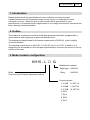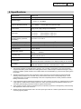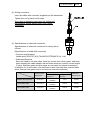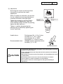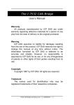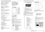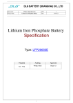
1
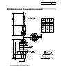
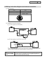
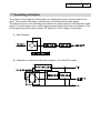
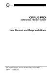
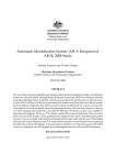
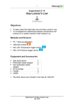
TY-KH15-014A
エ
○
KH15
Waterproof Pressure Transmitter
USER’S MANUAL
(KH15-L□G)
Thank you for choosing to purchase the KH15 pressure
transmitter.
Before using your new transmitter, please read through this
manual to familiarize yourself with its functions.
2014.11
7.1
TY-KH15-014A
Cautions for proper and safe operation
To use this product accurately and safely, carefully read this manual and the operation
manual Incorrect usage may cause malfunction and result in human injury, accidents, etc.
The cautions and warnings in the document are indicated by the following:
WARNING
Indicates that incorrect use may result in service injury or loss of life.
CAUTION
Indicates that incorrect use may result in risk of injury or property damage.
1. Do not apply more than the maximum allowable pressure.
Human injury or damage to surroundings may result due to explosion
or breakdown of the pressure elements.
2. Do not use this product on measured objects which are corrosive to
fluid or gas contacting areas.
Human injury or damage to surroundings may result due to explosion
or breakdown of the pressure elements and exposure of dangerous
measured objects.
3. Do not apply excessive weight, vibration or shock.
Human injury or damage to surroundings may result due to explosion
or breakdown of the pressure elements and exposure of dangerous
measured objects.
4. Use with the unspecified power supply may cause fire hazard or
electric shock.
5. Use with the instrument temperature range.
Use outside the instrument temperature range may cause human
injury or damage to surroundings due to explosion of breakdown of
this product.
WARNING
6. Connect wiring accurately according to the wiring drawings or
instructions in the operation manual.
Incorrect wiring may result in human injury or fire hazard.
7. Use devices with an explosion-proof construction when operating in
place liable to have explosive gas.
Danger of ignition and explosion.
8. Where the measurement object is oxygen, use oil-proof product.
In case of ordinary product, there is a possibility that oil remains inside the
product. It may cause ignition or explosion by reaction with oxygen
9. Perform installation carefully according to the installation instructions of
the instruction manual.
10. Do not alter this product. Also do not remodel this product by adding new
functions. Contact our company for repairs.
11. Since this product is a precision measuring instrument, keep the product
as far away from noise source as possible.
Also, remove noise from the power source by using noise filter, etc.
Note: Inform us in advance when using this product in a way that may result in
fatal or serious injury due to malfunction or incorrect operation.
TY-KH15-014A
1/14
CONTENTS
1. Introduction .....................................................................................................2
2. Outline .............................................................................................................2
3. Model number configuration ............................................................................2
4. Specifications ..................................................................................................3
5. Outline drawings (Representative example) ....................................................4
6. Wiring connection diagram and external connection .......................................5
7. Operating principles ........................................................................................6
8. Precautions for use .........................................................................................7
(1) Installation..................................................................................................7
(2) Wiring connection ......................................................................................8
(3) Specifications of cable with connector .......................................................8
(4) Cautions for transportation and control ......................................................9
(5) Cautions for storage ..................................................................................9
9. Operation ........................................................................................................9
10. Maintenance and adjustment ......................................................................10
(1) Maintenance ............................................................................................10
(2) Adjustment ............................................................................................... 11
(3) Countermeasures against noise ..............................................................13
11. Warranty ......................................................................................................14
12. Others .........................................................................................................14
TY-KH15-014A
2/14
1. Introduction
Please double-check the specifications for the model that you have received.
If specifications such as the pressure range, power source, or output are incorrect,
accidents can occur. Please be sure to use a model that is appropriate for your
specifications, in a location which is appropriate for your usage environment, and which has
been correctly wired and installed.
2. Outline
This product is a waterproof miniature solid-state pressure transmitter equipped with a
semiconductor strain gauge as its pressure detection part.
The diaphragm material used for the sensor components is SUS316L, which is highly
corrosion-resistant.
The standard outputs are 4 to 20mA DC, 0 to 5V DC, and 1 to 5V DC. In addition, it is
designed to be accessible for zero and span adjustments by removing the screw on the top
surface of the case.
3. Model number configuration
KH15 - L
□
G
Wetted parts material
Diaphragm :SUS316L
Model
Fitting
:SUS316L
Connector type External adjustment method
Connecting size:
2: G1/4B
K: NPT1/4
3: G3/8B
L: NPT3/8
4: G1/2B
M: NPT1/2
6: R1/8
7: R1/4
8: R3/8
9: R1/2
TY-KH15-014A
3/14
4. Specifications
Model number
KH15-L□G
Pressure sensor sealing type
Welding type
Pressure range *1
-0.1 to 0.5 ⇒ -0.1 to 2MPa
0 to 0.5 ⇒ 0 to 35MPa
Maximum allowable pressure *2
0.5 to 2MPa : 1.5 times high for the pressure range
3.5 to 35MPa : 1.2 times high for the pressure range
Power source
24V DC ±10% or 12V DC ±10%, 15 V DC ±10%
(Only power-supply voltage can be selected)
Output type
4 to 20mA DC
(Load resistance: 500Ω max.)
1 to 5V DC
(Load resistance: 10kΩ min.)
0 to 5V DC
(Load resistance: 10kΩ min.)
Accuracy
(including linearity, hysteresis,
repeatability)
±0.5%F.S. or ±1.0%F.S.
Operating temperature range
-20 to 70°C (No freezing or condensation) *3
Storage temperature range
-30 to 80°C (No freezing or condensation)
Temperature characteristics
±0.1%F.S./°C (For both zero point and span)
Responsiveness
1 ms or shorter
Wetted parts material
Diaphragm : SUS316L
Fitting
: SUS316L
Connecting size
G1/4B, G3/8B, G1/2B, R1/8, R1/4, R3/8, R1/2,
NPT1/4, NPT3/8, NPT1/2
Weight
Approx. 240g (including 2m cable)
Case structure *4
IP67
(The 0.5H submersion confirmation at 1m depth (according to JIS C 0920))
CE marking *5
Applicable Directive: 2004/108/EC
Applicable Standards: EN61326-1:2006 EN61326-2-3:2006
*1: Atmospheric pressure is transmitted to the gauge by way of a cable; consequently, in the case of pressure
ranges below 1MPa, please refrain from sealing the end of the cable with tape or adhesives during the wiring
process. In addition, please avoid the use of cables which are not breathable (e.g. which lack an opening down
the middle).
*2: Allowable maximum pressure is the upper limit to which pressure may be temporarily increased while still
allowing normal pressure to be resumed, when pressure levels return to the normal (rated) range. It is not
guaranteed to have no impact on functionality in the case of repeated pressure or static pressure increases
lasting 10 minutes or more.
*3: If the wetted part reaches temperatures exceeding 70°C (due to steam, hot water, etc.), please be sure to install
a pipe siphon or similar device to keep it below 70°C. Also, when measuring low-temperature fluids such as
cold water, please employ preventive measures against condensation.
*4: Case and the connector portion is waterproof (IP67), but please pay attention to the tightening of the fastening
and adjustment screws of the connector.
*5: Please connect the product before use to an indoor power grid under 30 m which is protected from overvoltage
caused by lightning strikes.
TY-KH15-014A
5. Outline drawings (Representative example)
* The hexagonal fitting is inscribed with “LC”.
4/14
TY-KH15-014A
5/14
6. Wiring connection diagram and external connection
(1) Wire connection
2-wire
3-wire
A: Red
Power (+)
A: Red
Power (+)
C: White
Power (-)
C: White
COM
–
E: Green Output
(2) Examples of external connection
e.g. 1) 2-wire system (4 to 20mA DC)
e.g. 2) 3-wire system (1 to 5V DC, 0 to 5V DC)
* When connecting a device which may cause power surges from the same power
supply, install a varistor as a countermeasure to protect KH15.
CAUTION
• Before installation, please check the rated value of the specifications for this
product and select an appropriately rated power supply. After double-checking
the load resistance of this product, please use adaptation equipment with
internal resistance within that rated range.
TY-KH15-014A
6/14
7. Operating principles
The pressure receiving part of this product is a diaphragm which converts pressure into
strain. The amount of the strain is detected by the semiconductor strain gauge.
The detection circuit is the full bridge type whose four sides consist of semiconductor strain
gauge. From this bridge circuit, electric signals proportional to the strain are obtained. Then
by the signal conversion shown below, DC electricity or DC voltage is transmitted.
(1) Block diagram
(2) Example of a structure of the above diagram (4 to 20mA DC output)
TY-KH15-014A
7/14
8. Precautions for use
(1) Installation
1) When this product is connected to the pressure line, do NOT tighten the main
body of the case with pipe wrench or similar.
For installation, make sure to use hexagonal part of connection screw.
2) When installing to pressure line, do NOT install the product while the liquid is filled
up in the pipe.
Since liquid is incompressible, tightening a connecting screw may generate high
pressure and instrument failure.
When installing to the existing pressure line or in the case of replacement, drain
the liquid inside the piping connection side and install the product with leaving air
of about 15 to 20mm.
3) Although this product has high vibration resistance, since this product is a
measuring instrument, be careful not to apply severe vibration.
4) Installation position may be vertical, front to back, side to side, or horizontal.
5) This product has protection code IP67 (JIS C 0920). However, for longer use,
select a location that is not affected by direct sunlight, dump, dust, oil or water.
• The transmitter should be used in ambient temperature -20 to 70 °C.
• While installing piping during installation, do not administer any strong shocks
to the product such as thumping or dropping it.
• Please maintain enough space around the product to allow for maintenance and
adjustment.
CAUTION
• If the wetted part reaches temperatures exceeding 70°C (due to steam, hot
water, etc.), please be sure to install a pipe siphon or similar device to keep it
below 70°C. Also, when measuring low-temperature fluids such as cold water,
condensation may form on the detecting sensor, which can cause accidents.
Please employ preventive measures against condensation.
• Please do not insert wires, etc., into the pressure feed port. This may damage
the diaphragm and prevent it from operating normally.
• Please wrap tapered pipe threads in plumber’s tape to prevent leaks.
• If using straight pipe threads, please check for debris, dirt, and damage to the
washer and seal face before installation to prevent leaks.
• If there is a danger of surge pressure, please concurrently use a damper and
joint with throttle.
• Always avoid pulling or severely bending cables. Also, during installation, be
careful not to hang the full weight of any cables from this product.
TY-KH15-014A
8/14
(2) Wiring connection
Insert the cable with connector supplied into this transmitter.
Tighten the nut by hand until it stops.
Since lack of tightening can impair the waterproof
performance, please tighten firmly until it stops
completely.
(3) Specifications of cable with connector
Specifications of cable with connector for wiring are as
follows;
[Specifications of cable with connector]
• Common specifications
Usable plug: R04-P6F (6.8) (TAJIMI ELECTRONICS Co., Ltd.)
• Cable specifications
Since the cable is a 4-wire cable, there are 4 wires (red, white, green, and blue)
when stripping the cable sheath; red and white wires are used for current output
(2-wire); however green and blue wires are not used (no internal connection).
In addition, for 3-wire cable, note that there is blue wire other than red and white
wires, however the green wire is not used (no internal connection).
Environmental
temperature
Conductor
Cross-sectional
area (mm2)
Configuration
(pcs/mm)
Cable outer
diameter (mm)
Shielded cable (standard)
-20 to 60°C
0.2
(AWG25)
7/0.18
6.2 DIA.
Heat-resistant cable
-20 to 105°C
0.3
(AWG23)
12/0.18
6.0 DIA.
Cold-resistant cable
-40 to 80°C
0.3
(AWG23)
12/0.18
6.0 DIA.
TY-KH15-014A
9/14
(4) Cautions for transportation and control
1) Cautions for transportation
Since this product is a precision measuring instrument, pay enough attention
when transporting the product. Drop or shock may cause a fatal damage.
2) Cautions for unpacking
Before unpacking, check the appearance of the package.
When unpacking, handle the package with care.
When bringing out the product from the packaging box, be careful not to drop the
product.
After unpacking, check if there is any damage on the external surface and the
product type is correct as it is ordered.
If any abnormality is found, make contact with the distributor or NKS sales office.
(5) Cautions for storage
To avoid failures or damages, do not store this product in the places where:
• exposed to water.
CAUTION
• susceptible to adverse effects due to air pressure, temperature, humidity,
ventilation, sunlight, particles, salt or sulfur in the air.
• exposed to inclination, vibration or shock. (including during transportation)
• exposed to chemicals (chemicals’ storage area) or gas.
• exposed to direct sunlight or high temperature in a car, etc.
9. Operation
Before powering on, double-check to make sure all wires have been correctly connected.
Also, double-check the voltage rating and amperage rating of the power supply and the
internal resistance of the external adaptation equipment, to be sure they are within the
rated range of this product’s load resistance.
Begin running properly after powering on, a 5-minute warm-up, and zero point adjustment
in stable condition.
Observe the following precautions while operating:
CAUTION
• Avoid the application of pressure ratings above those on this product’s
faceplate.
• Do not adjust the wiring while the device is powered on, as this may damage the
device and/or cause an electric shock. All wiring should be connected
according to the wiring diagrams.
TY-KH15-014A
10/14
10. Maintenance and adjustment
(1) Maintenance
This product will age at a rate proportional to its conditions of use. Please conduct a
routine inspection at least once every 6 months and recalibrate the device as
necessary.
Also, please recalibrate the device using a set method or recalibration mechanism.
The following is a routine inspection checklist for your reference and use.
<Routine Inspection Checklist>
• Appearance. (for scratches, cracks, warping, corrosion, etc.)
• Corrosion status of pressure inlet.
• Insulation resistance between each terminal and the case.
(100MΩ or more at 50V DC)
• Check for leakage and re-tightening of connecting screw.
• Output check by a reference pressure gauge.
• Avoid electrostatic-charge.
CAUTION
• When cleaning this instrument, use a soft damp cloth.
Do NOT use thinner or benzines which cause deterioration and failure.
TY-KH15-014A
11/14
(2) Adjustment
Removing two screws on the top allows
this product to perform the output
adjustment.
When 2 screws are removed, you can find
the zero adjustment and span adjustment
trimmers as shown in the right figure.
Tighten the screws to a torque of about
6cN•m after the adjustment. (After the
screw seating surface touches the packing,
tighten the right half-turn.)
Zero adjustment
trimmer
Span adjustment
trimmer
Tighten it carefully because that the
packing may be twisted by tightening the
screws vigorously.
Usable driver :
Tip thickness (W) = 0.2 to 0.4mm
Tip width (H) = 1.2 to 1.4mm
Axis diameter (D) = 1.8DIA.
Axis length (L) = 15mm or more
Recommended driver :
VESSEL ceramic adjustment driver
No.9000 (㊀1.3 × 30)
Recommended driver
• Do not attempt adjustments while the product is wet. Allowing water to enter the
product can cause accidents.
• Please make adjustments after the product has been powered on and warmed
up for 5 minutes.
CAUTION
• Avoid putting an excessive load on the trimmers. This may damage (the circuits
of) the trimmers.
• Be extremely careful not to cause a short circuit with your screwdriver.
(Use of a plastic or ceramic screwdriver is recommended.)
• Use a pressure reference or measuring device with good traceability for
adjustments.
TY-KH15-014A
12/14
1) Zero point adjustment
Zero point adjustment is performed by rotating zero point adjustment trimmer with
slotted screwdriver. However, the adjustment method differs between positive
pressure range and compound pressure range as follows:
<Positive pressure range>
Adjust the output in air-ventilated (unpressurized) status to 4mA DC for current
output, 1V DC or 0V DC for voltage output.
<Compound pressure range>
Output value in air-ventilated status is calculated according to the following
formula.
• In case of current output (4 to 20mA DC)
[output mA in atmosphere release state]
= ([16mA] / ([Upper limit output in range (MPa)] – [0.1MPa])) x 0.1 + [4mA]
e.g.) 0.5MPa, Compound pressure range: 6.67mA,
1.0MPa, Compound pressure range: 5.45mA
• In case of voltage output (1 to 5 VDC)
[output V in atmosphere release state]
= ([4V] / ([Upper limit output in range (MPa)] - [-0.1MPa])) x 0.1 + [1V]
e.g.) 0.5MPa, Compound pressure range: 1.667V,
1.0MPa, Compound pressure range: 1.364V
• In case of voltage output (0 to 5 VDC)
[output V in atmosphere release state]
= ([5V] / ([Upper limit output in range (MPa)] - [-0.1MPa])) x 0.1 + [0V]
e.g.) 0.5MPa, Compound pressure range: 0.833V,
1.0MPa, Compound pressure range: 0.454V
CAUTION
• Do not rotate span adjustment trimmer (“S”) during zero point adjustment.
TY-KH15-014A
13/14
2) Span adjustment
Except under special circumstances, please refer all span adjustment to our
company.
Do not attempt span adjustment without a pressure reference device.
When attempting span adjustment with a pressure reference device, please follow
the instructions below. Also, be careful of reversed output and alteration to the
output values of compound gauges.
‹1› Adjust zero output, as described in “1) Zero point adjustment”.
‹2› In addition to the upper limit of the pressure range, use the span adjustment
trimmer to adjust the span output with the current output to 20mA DC and the
voltage output to 5V DC (or the span value).
‹3› Continue to repeat and alternate ‹1› and ‹2› to adjust the zero and span.
CAUTION
• Do not change zero point adjustment while rotating span adjustment trimmer
(“S”).
• Avoid the application of pressure ranges above those on the device’s faceplate.
(3) Countermeasures against noise
Noise problems are complicated, and often difficult to solve theoretically.
Countermeasures are mostly incomplete.
If measured values fluctuate from time to time or differ from the actual pressure
value, they may be affected by noise.
If noise is overlapped on the power supply lines, find out where the noise comes
from, and provide appropriate measures at the source of noise.
If the noise is constant, use of a noise filter is effective.
It is also important to use other power lines that are free from noise.
Noise may be introduced to signal lines through external induction. It is necessary
to provide suitable measures, such as moving the noise source to a remote place,
using magnetic or antistatic shield.
These countermeasures also apply to surge.
TY-KH15-014A
14/14
11. Warranty
If the delivered product is determined to be non-compliant due to "defects in manufacture or
design" within the warranty period (1 year from delivery to the customer), Nagano Keiki will
repair the product or exchange it for a compliant product at no cost.
Obvious traces of misuse, including deformation of parts, wear, or burnout, shall exempt the
device from its warranty, regardless of customer’s awareness of improper handling.
(1) If the delivered product is dismantled, modified, has any parts replaced, or features
added by the customer or a third party besides us.
(2) If the instructions detailed in this manual or the catalog are not followed.
(3) Deterioration from use, natural disasters, fire, or other force majeure.
(4) Secondary damage caused by product incompatibility, including those items listed
above.
Obvious traces of misuse, including deformation of parts, wear, or burnout, shall exempt the
device from its warranty, regardless of customer’s awareness of improper handling.
12. Others
This manual is not intended to cover all details of the equipment.
Nor is it intended to cover all details relating to installation and maintenance.
If you require a more detailed explanation, or the device does not adequately serve your
company’s intentions, please inquire with us.
Some of the information in this instruction booklet may change without notice due to revisions, etc.
Website: http://www.naganokeiki.co.jp
Headquarters
30-4, Higashimagome 1-chome, Ota-ku,Tokyo,
Japan 143-8544