1
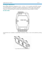
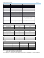
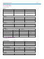
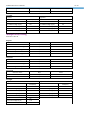
DAM-E3025
User’s Manual
Beijing ART Technology Development Co., Ltd.
DAM-E3025 User’s Manual
V6.10
DAM-E3025 Module
Introduction
Features
6-ch Isolated Digital Input/ 5-ch Power Relay Output
General
¾
Power Consumption: 2.5W@24VDC
¾
Power Supply: unregulated 10~30VDC
¾
Support double watchdogs
¾
Support 10/100Mbps Ethernet
¾
Provide default web page or custom-built web page
Digital Input
¾
Channels: 6
¾
Input
Dry Contact: Grounding or open circuit
Wet Contact: Logic Level 0: +1V max, Logic Level 1: 4V~30V
¾
Isolated Voltage: 3750V
¾
Input channel can be used as a 500Hz counter
Relay Output (A-type)
¾
Channels:5
¾
Output Mod: common anode
¾
Contact Rating: 250VAC@1A
30VDC@2A
¾
Relay on Time: 7ms
¾
Relay off Time: 3ms
¾
Breakdown Voltage : 500VAC
¾
Insulation Resistance: ≧1000MΩ
Easy to operate
DAM-E3025 utility software can help you to select configuration, set the operating parameter for your
process control needed.
Industrial Design
DAM-E3025 was designed to use in industrial environment. It can be installed in standard DIN rail inside
the cabinet. And it can be powered by unregulated 10~30VDC to meet the various power supplied source
in field. It also withstands ambient temperature up to 60℃ and resists the effects of vibration and
mechanical shock.
DAM-E3025 User’s Manual
V6.10
Wiring & Installation
Power supply requirements: unregulated +10 VDC ~ +30 VDC. "+Vs" is a positive, and "GND" is ground.
The Ethernet interface is connected to a computer switch directly via network cable. If the wiring and
power is ok, then the power indicator should be stop flash and keep on. The module initialization is
completed. The indicator flashes according to the transmitted data when the module is working.
DAM-E3025
Fig.1 DAM-E3025 Drawing
DAM-E3024 can be installed in standard DIN rail inside the cabinet; it also can be installed by stacking
mode.
Fig.2 DAM-E3025 standard DIN installation
DAM-E3025 User’s Manual
V6.10
Fig.3 DAM-E3025 stack installation
Application Wiring
Fig.4 Dry contact signal input
Fig.5 Wet contact signal input
Fig.6 TTL/CMOS signal input
DAM-E3025 User’s Manual
V6.10
Fig.7 Open-collector signal input
Default Setting
If the module’s network configuration is wrong, or forget the last modified value, the module can be reverted to default
settings. Steps: short-circuit the “INIT*” and “GND” when there is no power; power-on for 3 seconds, power off,
disconnect “INIT*” and “GND”. The module is reverted to the default settings.
1. IP Address: 192.168.2.80
2. Subnet Mask: 255.255.255.0
3. Default Gateway: 192.168.2.1
4. TCP Port: 502
5. HTTP Port: 80
Communication Protocol
At present, Ethernet Distributed Acquisition Modules of our company use MODBUS TCP mode. Supported function
code includes the following categories:
01 READ COIL STATUS
02 READ INPUT STATUS
03 READ HOLDING REGISTERS
04 READ INPUT REGISTERS
05 FORCE SINGLE COIL
06 PRESET SINGLE REGISTER
15 FORCE MULTIPLE COILS
16 FORCE MULTIPLE REGISTERS
20 READ FILE RECORD
21 WRITE FILE RECORD
Address Mapping Table
Read Relay Status
Function Code: 01
Description: Read the state of the output relay
Data Description:
Address
00001-00005
Description
For Switch Output Current Status
Note
5 Channels, 1 for H Level,0 for L level
DAM-E3025 User’s Manual
Reservation
00033-00037
Reservation
00065-00069
Reservation
V6.10
For Switch Output Power-on Status
5 Channels, 1 for H Level,0 for L level
For Switch Output Safe Status
5 Channels, 1 for H Level,0 for L level
Request
Domain Name
Byte
Value
Function Code
1 byte
0×01
Start Address
2 bytes
0×0000 to 0×FFFF
Read Amount
2 bytes
1 to 2000 (0×7D0)
Domain Name
Byte
Value
Function Code
1 byte
0×01
Byte Count
1byte
n= (Read Amount+7)/8
Coil Status
n bytes
Response
Exception
Domain Name
Byte
Value
Function Code
1 byte
0×02+0×80
Error Code
1 byte
0×1 or 0×2
Example
Request
Response
Domain Name
Domain Name
Data (hex)
01
Function Code
Start Address H(byte)
Function Code
Byte Count
00
Data (hex)
01
03
13
27(h)~20 status
CD
Read Amount H (byte)
00
Read Amount L (byte)
13
35(h)~28 status
38(h)~36 status
6B
05
Start Address L(byte)
Read Switch Input
Function Code: 02
Description:Read input switch status
Data Description
Address
10001-10005
Description
Note
For Switch Input Status
6 Channels, 0 for no power, 1 for power on
For Rising Edge Latched Status
6 Channels, 0 for No Latch, 1 for Latch
For Falling Edge Latched Status
6 Channels, 0 for No Latch, 1 for Latch
Reservation
10033-10038
Reservation
10065-10070
Reservation
Request
Domain Name
Byte
Value
Function Code
1 byte
0×02
Start Address
2 bytes
0×0000 to 0×FFFF
DAM-E3025 User’s Manual
V6.10
Read Amount
2 bytes
1 to 2000 (0×7D0)
Domain Name
Byte
Value
Function Code
1 byte
0×02
Byte Count
1 byte
n= (Read Amount+7)/8
Input Status
n bytes
Response
Exception
Domain Name
Byte
Value
Function Code
1 byte
0×02+0×80
Error Code
1 byte
0×1 or 0×2
Example
Request
Response
Domain Name
Domain Name
Data (hex)
02
Function Code
Data (hex)
02
Function Code
Byte Count
Start Address H(byte)
00
Start Address L(byte)
C4
204(h)~197 status
AC
Read Amount H (byte)
00
Read Amount L (byte)
16
212(h)~205 status
218(h)~213 status
DB
35
03
Read Holding Register
Function Code: 03
Note: Read the holding register value
Data Description:
Address
Description
Note
40001
For Ch01 Pulse Output L Level
16 bits
40002
For Ch01 Pulse Output H level
16 bits
40003
For Ch02 Pulse Output L Level
16 bits
40004
For Ch02 Pulse Output H level
16 bits
40005
For Ch03 Pulse Output L Level
16 bits
40006
For Ch03 Pulse Output H level
16 bits
40007
For Ch04 Pulse Output L Level
16 bits
40008
For Ch04 Pulse Output H level
16 bits
40009
For Ch05 Pulse Output L Level
16 bits
40010
For Ch05 Pulse Output H level
16 bits
40011
For Ch06 Pulse Output L Level
16 bits
40012
For Ch06 Pulse Output H level
16 bits
40065
For Ch01 Switch Pulse Count L
16 bits
40066
For Ch01 Switch Pulse Count H
16 bits
40067
For Ch02 Switch Pulse Count L
16 bits
40068
For Ch02 Switch Pulse Count H
16 bits
40069
For Ch03 Switch Pulse Count L
16 bits
40070
For Ch03 Switch Pulse Count H
16 bits
40071
For Ch04 Switch Pulse Count L
16 bits
Reservation
DAM-E3025 User’s Manual
V6.10
40072
For Ch04 Switch Pulse Count H
16 bits
40073
For Ch05 Switch Pulse Count L
16 bits
40074
For Ch05 Switch Pulse Count H
16 bits
40075
For Ch06 Switch Pulse Count L
16 bits
40076
For Ch06 Switch Pulse Count H
16 bits
40129
For Pulse Output Enable Register
Set bit: Enabled; Space: Disabled
40130
For Input Latch Enable Register
Set bit: Enabled; Space: Disabled
40131
For Input Count Enable Register
Set bit: Enabled; Space: Disabled
40132
For Input Count Mode Register
Set bit: Rise; Space: Fall
40513
For Watchdog Control Register
bit0: 0 disabled, 1 enabled
bit1: 0 normal, 1 overflow
bit2: 0 normal, 1reset
40514
For Watchdog Overflow Register
Watchdog Overtime Constant
40515
For Watchdog Reset Register
0x55AA
Reservation
Reservation
Reservation
Request
Domain Name
Byte
Value
Function Code
1 byte
0×03
Start Address
2 bytes
0×0000 to 0×FFFF
Read Amount
2 bytes
1 to 125 (0×7D)
Domain Name
Byte
Value
Function Code
1 byte
0×03
Byte Count
1 byte
2n
Input State
2n bytes
Response
Exception
Domain Name
Byte
Value
Function Code
1 byte
0×03+0×80
Error Code
1 byte
0×1 or 0×2
Example
Request
Domain Name
Function Code
Response
Data (hex)
03
Domain Name
Function Code
Byte Count
Data (hex)
03
Start Address H(byte)
00
Start Address L(byte)
08
Holding Registers High
00
Read Amount H (byte)
00
Holding Register Low
0A
Read Amount L (byte)
01
02
Note 1: The unit of the pulse output level width: millisecond
The unit of the watchdog timer length: millisecond
Note 2: When power on, the highest bit of the watchdog control register is 1, can be done to do determine whether the
DAM-E3025 User’s Manual
V6.10
module is rested or not.
Write Single Relay
Function Code: 05
Request
Domain Name
Byte
Value
Function Code
1 byte
0×05
Address Setting
2 bytes
0×0000 to 0×FFFF
Content Setting
2 bytes
0x0000 or 0xFF00
0x0000 release relay
0xFF00 engage relay
Domain Name
Byte
Value
Function Code
1 byte
0x05
Address Setting
2 bytes
0x0000 to 0xFFFF
Content Setting
2 bytes
0x0000 or 0xFF00
Exception
Domain Name
Byte
Value
Function Code
1 byte
0x05+0x80
Error Code
1 byte
0x1 or 0x2
Response
Example
Request
Domain Name
Function Code
Response
Domain Name
Data (hex)
05
Data (hex)
05
Function Code
Set Address H(byte)
00
Set Address H(byte)
00
Set Address L(byte)
05
Set Address L(byte)
05
Set Content H (byte)
FF
Set Content L (byte)
00
Set Content H (byte)
Set Content L (byte)
FF
00
Set Single Holding Register
Function Code: 06
MODBUS Request
Domain Name
Byte
Value
Function Code
1 byte
0×06
Address Setting
2 bytes
0×0000 to 0×FFFF
Content Setting
2 bytes
0×0000 to 0×FFFF
MODBUS Response
Domain Name
Byte
Value
Function Code
1 byte
0×06
Address Setting
2 bytes
0×0000 to 0×FFFF
Content Setting
2 bytes
0×0000 to 0×FFFF
Byte
Value
Exception
Domain Name
DAM-E3025 User’s Manual
V6.10
Function Code
1 byte
0×06+0×80
Error Code
1 byte
0×1 or 0×2
Example
Request
Domain Name
Data(hex)
Domain Name
Data(hex)
Function Code
06
Function Code
06
Set Address High (byte)
00
Set Address High (byte)
00
Set Address Low (byte)
08
Set Address Low (byte)
08
Set Content High (byte)
00
Set Content High (byte)
00
Set Content Low (byte)
19
Set Content Low (byte)
19
Response
Multiple Relay Setting
Function Code: 0F
Request
Domain Name
Byte
Value
Function Code
1 byte
0×0F
Start Address Setting
2 bytes
0×0000 to 0×FFFF
Length Setting
2 bytes
0×0000 to 0×07B0
Byte Count
1 byte
n
Content Setting
n bytes
Response
Domain Name
Byte
Value
Function Code
1 byte
0×0F
Start Address Setting
2 bytes
0×0000 to 0×FFFF
Length Setting
2 bytes
0×0000 to 0×07B0
Exception
Domain Name
Byte
Value
Function Code
1 byte
0×0F+0×80
Error Code
1 byte
0×1 or 0×2
Example
Request
Domain Name
Data(hex)
Domain Name
Data(hex)
Function Code
OF
Function Code
OF
Set Address High (byte)
00
Set Address High (byte)
00
Set Address Low (byte)
13
Set Address Low (byte)
13
Set Amount High (byte)
00
Set Amount High (byte)
00
Set Amount Low (byte)
0A
Set Amount Low (byte)
0A
Byte count
Set Content High (byte)
02
CD
Set Content Low (byte)
01
Response
DAM-E3025 User’s Manual
V6.10
Set Multiple Holding Registers
Function Code: 10
Request
Domain Name
Byte
Value
Function Code
1 byte
0×10
Start Address Setting
2 bytes
0×0000 to 0×FFFF
Length Setting
2 bytes
0×0000 to 0×07B0
Byte Count
1 byte
2n
Content Setting
2n bytes
Response
Domain Name
Byte
Value
Function Code
1 byte
0×10
Start Address Setting
2 bytes
0×0000 to 0×FFFF
Length Setting
2 bytes
0×0000 to 0×07B0
Exception
Domain Name
Byte
Value
Function Code
1 byte
0×10+ 0×80
Error Code
1 byte
0×1 or 0×2
Example
Request
Domain Name
Function Code
Data(hex)
Response
Domain Name
Data(hex)
Function Code
Set Address High (byte)
10
00
Set Address High (byte)
10
00
Set Address Low (byte)
01
Set Address Low (byte)
01
Set Amount High(byte)
00
Set Amount High(byte)
00
Set Amount Low (byte)
02
Set Amount Low (byte)
02
Byte Count
Set Content High (byte)
04
00
Set Content Low (byte)
0A
Set Content High (byte)
01
Set Content Low (byte)
02
Read File Record
Function Code: 14/06
Read file record: in MODBUS, file is considered to be 16-bit array, addressing according to address. Read file: set the
start address and read length and change the Start Address and Read Length can traverse the entire file. The file does not
have a name, it has number only. You can only read and write one file at one time.
Request
Domain Name
Byte
Value
Function Code
1 byte
0×14
Byte Count
1 byte
0×07 to 0×F5
DAM-E3025 User’s Manual
V6.10
Sub Function Code
1 byte
0×06
File Number
2 bytes
0x0000 to 0xFFFF
Record Number
2 bytes
0x0000 to 0x270F
Read Length
2 bytes
n
Sub Function Code
1 byte
0x06
……
……
Domain Name
Byte
Value
Function Code
1 byte
0×14
Byte Count
1 byte
0x07 to 0xF5
Sub Function Byte Count
1 byte
0x07 to 0xF5
Sub Function Code
1 byte
0x06
Data
2n bytes
Response
Exception
Domain Name
Byte
Value
Function Code
1 byte
0×14+ 0×80
Error Code
1 byte
0×1 or 0×2
Example
Request
Domain Name
Data(hex)
Function Code
Response
Domain Name
Data(hex)
Function Code
Byte Count
14
07
Byte Count
14
06
Sub Function Code
06
Respond Count
05
File Number High (byte)
00
Sub Function Code
06
File Number Low(byte)
04
Record Data High(byte)
0D
Record Number High(byte)
00
Record Date Low(byte)
FE
Record Number Low(byte)
Record Data High(byte)
Read Length High(byte)
01
00
00
20
Read Length Low(byte)
02
Record Date Low(byte)
Write File Record
Function Code: 15/06
Request
Domain Name
Byte
Value
Function Code
1 byte
0×15
Byte Count
1 byte
0×07 to 0×F5
Sub Function Code
1 byte
0×06
File Number
2 bytes
0x0000 to 0xFFFF
Record Number
2 bytes
0x0000 to 0x270F
Write Length
2 bytes
n
Data
2n bytes
……
……
DAM-E3025 User’s Manual
V6.10
Response
Domain Name
Byte
Value
Function Code
1 byte
0×15
Byte Count
1 byte
0x07 to 0xF5
Sub Function Code
1 byte
0x06
File Number
2 bytes
0x0000 to 0xFFFF
Record Number
2 bytes
0x0000 to 0x270F
Write Length
2 bytes
n
Data
2n bytes
Exception
Domain Name
Byte
Value
Function Code
1 byte
0×15+ 0×80
Error Code
1 byte
0×1 or 0×2
Example
Request
Domain Name
Function Code
Data(hex)
Response
Domain Name
Data(hex)
Function Code
Byte Count
15
0B
Byte Count
15
0B
Sub Function Code
06
Sub Function Code
06
File Number High (byte)
00
File Number High (byte)
00
File Number Low(byte)
04
File Number Low (byte)
04
Record Number High(byte)
00
Record Number High(byte)
00
Record Number Low(byte)
Record Number Low(byte)
Read Length High(byte)
01
00
Read Length Low(byte)
02
Write Length High(byte)
Write Length Low(byte)
01
00
Write Data
4 bytes
Write Data
4 bytes
EEPROM Assignment
//file 0
#define MODULE_NET_ADDR
0x0000
#define MODULE_VER_ADDR
0x0020
//file 1
#define NET_CONFIG_ADDR
0x0000
//file 2
#define DIG_POWER_ADDR
0x0000
#define DIG_SAFE_ADDR
0x0004
#define CNT_CFG_ADDR
0x0080
//file3to file 7
……
Note:
EEPROM is 8kbyte capacity,divide to 8 file blocks, every block 1kbyte。
1. MODULE_NET_ADDR
02
DAM-E3025 User’s Manual
V6.10
Restore to factory defaults network configuration parameter.
Byte
Content
4
IP Address
4
Default Gateway
4
Subnet Mask
6
MAC Address
2. MODULE_VER_ADDR
Module Version Information:
Byte
Content
DAM-E3024
42byte
V6.20 2006.09.01 ID:DAME123456
3. NET_CONFIG_ADDR
Network configuration parameter, call table 1 for structures.
4. DIG_POWER_ADDR
Digital output power-on value, 2 bytes.
5. DIG_SAFE_ADDR
Digital output safe value, 2 bytes.