1
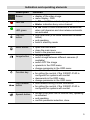
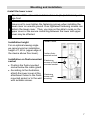
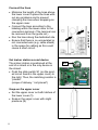
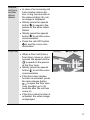
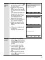
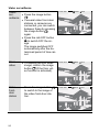
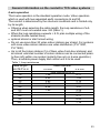
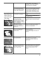
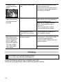
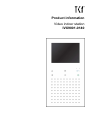
Product information Video indoor station IVX9001-0140 Table of contents Scope of delivery ...................................................................................3 Safety instructions ................................................................................3 Installation – protective measures .........................................................3 Device overview.....................................................................................4 Indication and operating elements .......................................................5 Intended use ..........................................................................................6 Short description ...................................................................................6 Mounting and installation .....................................................................7 Install the lower cover ...........................................................................7 Installation height ...............................................................................7 Installation on flush-mounted socket ..................................................7 Set indoor station as end device ...........................................................8 Snap-on the upper cover ......................................................................8 Open the device....................................................................................9 5-wire special operation ........................................................................9 Commissioning......................................................................................9 Settings ................................................................................................ 10 AS address-dependent image activateion ........................................... 10 Pre-settings ex works.......................................................................... 10 Configuration options .......................................................................... 11 Settings via OSD menus ..................................................................... 12 Operation ............................................................................................. 16 Sending a call ..................................................................................... 18 Switching lights and send control functions ...................................... 21 Automatic function............................................................................ 21 Setup Intercom................................................................................. 22 General information on the conduit in TCS video systems .............. 23 6-wire operation .................................................................................. 23 Max. number of IVX9001-0140 in 6-wire operation ............................. 24 Technical data ..................................................................................... 25 FAQ....................................................................................................... 26 Cleaning ............................................................................................... 28 Information on disposal ...................................................................... 29 Warranty ............................................................................................... 29 Service ................................................................................................. 30 2 Scope of delivery 1 x Video indoor station IVX9001-0140 Product information User manual Safety instructions ! Attention! Mounting, installation, commissioning and repair of electronic devices have to be carried out only by qualified electricians. Thus, the standards and instructions for the installation of systems have to be observed. For working on systems with main connection of 230 V alternating voltage, the safety requirements according to DIN VDE 0100 must be observed. When installing TCS:BUS systems, the general safety regulations for telecommunication systems according to VDE 0800 must be observed. Inter alia: separated conduit of heavy current and low current lines, minimum distance of 10 cm in case of a common conduit, use of separators between heavy and low current lines within shared cable ducts, use of standard communication, e.g. J-Y (St) Y with 0.8 mm diameter, existing lines (modernisation) with deviating cross-sections can be used in compliance with the loop resistance. Installation – protective measures ! With suitable measures to protect against lightning, it has to be ensured that a voltage of each 32 V DC is not to be exceeded at the connections a, b, P, M. 3 Device overview Screen Sensor buttons Image button LED red LED green Door release button Speech button (sensor button) Call OFF button Menu button Function key Loudspeaker Microphone 4 Indication and operating elements Description Function Screen display of the video image menu display, OSD LED red is ON: call OFF is activated (ring tone mute) blinks: indication busy voice channel LED green Call OFF button Menu button Image button Function key Door release button Speech button is ON: when a voice connection is established, when call diversion and door release automatic are activated ring tone mute (if no voice connection is established) end speaking back in stand-by mode open the main menu close the main menu back to the previous menu activate image switch image between different cameras (if available) switch OFF the image upwards in the OSD menu change parameter in the OSD menu send control function 8 for calling the central, if the IVX9001-0140 is configured for systems with central dwonwards in the OSD menu change parameter in the OSD menu door release during a voice connection for calling the central, if the IVX9001-0140 is configured for systems with central accept a call (door call or internal call), speaking is activated end speaking confirm parameter selection, store 5 Intended use The video indoor station IVX9001-0140 is a video indoor station with color display for hands-free talking. The IVX9001-0140 is suitable for the operation in building communication systems with combined audio / video systems. The operation is realised via the sensor buttons and the On-ScreenDisplay (OSD). The video indoor station IVX9001-0140 is suitable for surface-mount. ! The video indoor station is to be installed preferably on a wall outlet one gang box or a flush-mount socket, as the space for cabling is limited within the device. Short description 6 hands-free talking 13 ring tones, can be programmed by a qualified electrician door release button function key ring tone mute with optical indication LED red audio and video privacy function as well as an automatic call cut-off optical signaling of door and internal calls by a green LED optical indication of door stand-by time, on-service call by a green LED optical indication when activating door release automatic or call diversion by a green LED acoustic ring tone distiction in case of two different door calls (door call AS border ≥ 0), floor calls and internal calls adjustable functions in the OSD menu: AS-address, image switch time, length of call, OSD information, language, microphone sensitivity, conversation volume, ring tone volume, color saturation, brightness and contrast of the video image send control functions 8 (function key) button tone can be deactivated floor video image activation can be realised with an additional FBAS video input for another camera on terminal C optional: floor push button can be connected Mounting and installation Install the lower cover ! Attention! The video indoor stations have to (de-)installed only voltage-free! ! Ensure not to over-tighten the fastening screws when installing the lower cover on uneven ground. Over-tightened fastening screws can deform the lower cover. Thus, you may not be able to snap on the upper cover or the secure contacting between the lower and upper cover may be affected. Installation height Lower cover For an optimal viewing angle we recommend an installation height of 1,60 m (upper edge of the device above floor level). Position flushmounted socket Installation on flush-mounted socket 2 fastening screws on flushmounted socket Position the flush-mounted socket below the cable gland. According to the illustration, attach the lower cover at the 4 fastening attachment holes to the flush- screws wall mounted socket or to the wall mounting with suitable screws. 7 Connect the lines Set indoor station as end device The indoor station is positioned at the end of a strand or is the only device in the strand: Push the slide switch S1 (on the printed circuit board in the upper cover) to the right. Thus, the matching resistor is “placed“. (scope of delivery: “not placed“) Snap-on the upper cover Set the upper cover on both latches of the lower cover (1). Snap-in the upper cover with slight pressure (2). 8 a b E P M C V1 V2 Minimise the length of the lines above the lower cover to place the lines without any problems and to prevent clamping the lines when snapping-on the upper cover. Connect the lines according to the labeling within the lower cover to the connection terminal. (The terminal can be removed from the guide rail.) Run the lines along the dedicated site. Ensure that there is no uninsulated or not connected wire (e.g. cable shield) in the space for cabling as this could cause a short-circuit. S1 Open the device There is a release mechanism at the underside of the device. Slightly press into the opening with a screwdriver. Now the upper cover can be removed from the underside and separated from the lower cover. Lift the upper cover from the two upper latches. 5-wire special operation If there are only 5 wires available for the device, it is possible to operate it in 5-wire special operation. Connect the b- and M-wire with one wire bridge. Commissioning ! First install the system completely, then connect it to mains voltage! Install the devices of the system completely. V1 and V2 must not be connected to P-, a- or b-wire. When connecting the video wires V1 (+) and V2 (-) the polarity must be observed. Check the a-, b- and P-wire against each other for short-circuit. Switch ON the mains voltage. Both LEDs are blinking 3 x green. The indoor station is ready for operation. 9 Settings AS address-dependent image activation If there are also front-door stations without camera in combination with video front-door stations within one systems, the image is not activated if a call from such a front-door station comes in. To guarantee this function the possible AS addresses are separated into two areas: AS address 0 – 47* AS address 48 – 63* reserved for video frontdoor stations image is activated in case of a door call (of max.16 video front-door stations) free, for front-door stations image is not activated in without camera case of a door call *) The video AS border can be modified only with the configuration software configoTM. Pre-settings ex works OSD information Language Microphone sensitivity Conversation volume Ring tone volume Brightness Contrast Color intensity Length of call Remaining conversation time activation of the door opener Image switch time Blinking period of the red LED, BUS If ”video/speech channel busy“ when pressing the speech button or the image button if ”video/speech channel busy“ when a door call comes in (for image activation when busy) 10 activated German 5 (of 8) 3 (of 8) 5 (of 8) 4 (of 20) 10 (of 20) 14 (of 20) 10 to 120 s 4s 60 s 6s 3 x blinking 10 s 5 x blinking Internal stand-by time if the indoor station is called if the indoor station is calling and waiting for call acceptance Floor door release time Timeout OSD Timeout video image 2 min 30 s 35 s 10 bis 120 s 10 bis 120 s Configuration options Function Fixed simplex communication Simplex communication to the front-door station Ring tone volume Ring tones for door calls, internal calls and floor calls Call diversion Button tone ON / OFF Door release automatic Internal call (max. 10) Control function 8, 9, 10, light switch f. Determine video AS border and door call AS border Image activation when a floor call comes in (floor video function) Image switch time Length of call Parallel allocation Set / delete floor door release function Automatic hands-free talking after internal call ON/ OFF Image settings Menu – – x x x x x x x x x x x x x – x 11 Settings via OSD menu Setup the installer This level is permitted for authorised persons only. (Operat Press the menu button ing level in stand-by mode to open for the the main menu. qualified electrician ) Press the image button or the function key to select the menu Intercom settings. Press simultaneously the call OFF button and the image button to get to the menu Set up Installer. Main menu 1 2 3 4 Internal call Light and control Automatic function Setup Intercom Off Down OK Setup Intercom 1 Set up User 2 Set up Installer Off Up Down OK Set up Installer 1 2 3 4 5 6 Ring tone AS address Parameter Internal call System Information on device Off 12 up Up Dwown OK Ring tone In the menu ring tone, the ring tones for door calls from the front-door station (max. 8), floor calls and internal calls can be set. Press the image button or the function key to set the ring tones. When selecting the ring tone, the ring tone sounds immediately. Ring tone Door1 Tone: Door2 Tone: Door3 Tone: Door4 Tone: Door5 Tone: Door6 Tone: Door7 Tone: Door8 Tone: Internal call: Floor call: Off Up Alpha1 Alpha2 Alpha2 Alpha2 Alpha1 Alpha2 Alpha2 Alpha2 Gong Alpha3 Down OK Note: After you made the settings please press the speech button to store the settings and to switch to the next menu point. Video AS To one indoor station max. 8 border front-door stations can be allocated: AS address from 0 to 63: 0 - 47 for video front-door station, as of 48 for audio front-door station. Press the image button / function key to change the AS address. Press the image button or the function key to set the video AS border. AS address Door1 Door2 Door3 Door4 Door5 Door6 Door7 Door8 Off AS: AS: AS: AS: AS: AS: AS: AS: 0 empty empty empty empty empty empty empty Up Down OK Note: Store the settings by pressing the speech button . The next line is highlighted. 13 Parameter Image switch time: The screen switches OFF after the determined period of time (flat= 60 s). Length of call: The indoor station switches OFF after the determined period of time. The time can be adjusted from 10 to 120 s. Parallel SN: Enter the serial number of the indoor station which should be displayed when a call comes in. Floor camera: Activate / deactivate if another camera should be connected. Floor door (opener): Activate / deactivate Floor door opener is activated: By pressing the door release button the control function 11 is sent. Can be used to open the floor door. Call diversion: Activate / deactivieren Call diversion SN: Enter the serial number Door release automatic: Activate / deactivate Note: Store the settings by pressing the speech button . The selection symbol switches over to the next position. 14 Parameter Image switch time: 60 Length of call: 45 Parallel call SN: 21 Floor camera: deactivated Floor door: permitted Call diversion: permitted Call diversion SN: 0 Door automatic: deactivated Off Up Down OK Internal Enter the room and serial call (desnumber of the indoor station tinations) for internal calls. Max. 10 internal calls can be configured. Press the image button / function key to change the room and serial number. The numbers must be adjusted individually. Internal call 01: 02: 02: 02: 02: 02: 02: 02: 02: 02: Ro Ro Ro Ro Ro Ro Ro Ro Ro Ro Off 10000 0 0 0 0 0 0 0 0 0 Up SN: SN: SN: SN: SN: SN: SN: SN: SN: SN: 00000 0 0 0 0 0 0 0 0 0 Down OK Note: Store the settings by pressing the speech button . The selection symbol switches over to the next position. System OSD information: displays date, time and status etc., when a voice and video connections is established. Language: language setting OSD (German and others) MIC Vol: microphone sensitivity, 8 steps. SPK Vol: volume of the loudspeaker, 8 steps. Function key: CF 8 or lights. Factory setting Press the image button to reset the systems parameter to the factory settings. Reset User Einrichten OSD Info: Aktiv Sprache: German MIC Vol: Spk Vol: Funktionstaste: Werkseinstellung Reset Aus Auf Ab OK Note: Store the settings by pressing the speech button . The selection symbol switches over to the next position. Device information The information on the device is available under Device information. 15 Operation To accept a call Door call In case of an incoming call from a from a video front-door video station, the screen is aufronttomatically activated and door stathe video image is distion played. Shortly press the speech button to speak to the person who is in front of the door. Speaking End End When a voice connection is established, the LED 2 is ON. Shortly press the speech button to end the voice communication. Shortly press the door release button to open the door. Door call In case of an incoming call from an from an audio front-door audio station, a ring tone sounds frontat the indoor station. No door stavideo image is displayed. tion Shortly press the speech button to speak with the person in front of the door. Shortly press the speech button to end the voice communication. Press the call-OFF button to end the voice communication. 16 Remaining time Internal call from another indoor station In case of an incoming call from another indoor station, a ring tone sounds at the indoor station. No video image is displayed. Shortly press the speech button to speak to the person at the other indoor station. Shortly press the speech button to end the voice communication. Press the call-OFF button to end the voice communication. Floor call Floor door Open End When a floor call (from a floor door) comes in, shortly press the speech button to speak to the person at the floor door. Shortly press the speech button to end the voice communication. If the floor door release function is activated, press the door release button to open the floor door (only possible up to 35 seconds after the call has come in). If the floor video function is activated, the video image is displayed. 17 Call from the cen- In case of an incoming call from the central, shortly tral press the speech button to speak to the person at the central. Shortly press the speech button to end the voice communication. Sending a call Call a In stand-by mode: Press video the speech button to frontestablish a voice commudoor stanication with front-door tion station which was connected last. Shortly press the speech button to end the voice communication. 18 Front door Next End Send an internal call Press the menu button in stand-by mode to open the main menu. Press the image button or the function key to select the menu Internal call. If an internal call was configured, e.g. the room or the serial number of the call destination is displayed on the screen. Select the call destination (e.g. facility manager) Press the speech button to call another indoor station. Main menu If there is no internal call configured: Display: No internal call. Internal call 1 2 3 4 Internal call Light and control Automatic function Setup Intercom Off Up Down OK Internal call 01: Facility M. SN 12808 02: Ro 12 SN 54987 Off Up Down OK Down OK No internal call Off Call the central Up Press the door release button or the function key (depending on your configuration) to call the central. If a call comes in at the indoor station, press the speech button to speak with the person at the central. Shortly press the speech button to end the voice communication. 19 Video surveillance Video Press the image button sur. veillance If several video front-door stations or cameras are connected, you can switch between these by pressing the image button again. Press the call-OFF button to switch OFF the image. The image switches OFF automatically after the determined period of time ran out. Floor video To display the floor video image, confirm the image button (if the floor video function is activated). Video frontdoor station Press the image button to switch to the image of the video front-door station. 20 Front door Next End Floor door Next End Front door Next End Switching lights and send control functions Light and Press the menu button control in stand-by mode to open the main menu. Press the image button or the function key to select the menu Light and control. Press the image button or the function key to select a function (control function 8, 9, or 10 or send light switch function). Press the speech button to trigger the control function or to switch the lights. Main menu 1 2 3 4 Internal call Light and control Automatic function Setup Intercom Off Up Down OK Light and control 1 2 3 4 Control function 8 Control function 9 Control function 10 Light switch function Off Up Down OK Automatic function Automatic function (Etagentüröffner, Rufumleitung) Press the menu button in stand-by mode. Press the image button or the function key to activate / deactivate the function. Press the speech button to trigger the control function or to switch the lights. Automatic function Floor door: deactive Call diversion: deactive Off Up Down OK Note: Store the settings by pressing the speech button . 21 Setup Intercom Setup user (Operation level for the user) Press the menu button in stand-by mode. Press the image button or the function key to select the menu Setup Intercom. Press the speech button to get to the menu Setup user. Press the image button or the function key to change the parameter. Key tone: Activate / deactivate the key tone. Key tone is activated: When pressing the sensor button, a tone sounds. Setup Intercom 1 Setup User 2 Setup Installer Off Up Down OK Setup User Key tone: deactive Ring Vol: Brightness: Contrast: Color: Off Up Down OK Ring tone volume: Ring tone volume, 8 steps. Brightness: Screen brightness, 20 steps. Contrast: Image contrast, 20 steps. Color: Color saturation, 20 steps. Setup Installer 22 Operation level for the qualified electrician. This level is priorised for authorised persons only! For descriptions see Settings via OSD , page 12. General information on the conduit in TCS video systems 6-wire operation The 6-wire operation is the standard operation mode. Video operation which is used with two separated earth connections (b and M). The conduit is determined by the structural conditions and is limited only by its length. Observe when selecting the cable length: the loop resistance of a-b and M-P must not exceed max. 8 Ω (table 1). When the loop resistance exceeds > 8 Ω: plan multiple wiring of the strands (double twisted lines). optional strand or star formed wiring Do not use more than 20 video indoor stations per strand. For systems with more video indoor stations use video distributors (FVY1200, FVY1400). Up to 64 front-door stations (16 of them video front-door stations) and an almost unlimited number of indoor stations can be connected polarity-free (a/b) within one system (polarity-free only in 6-wire operation). Thus, a suitable power supply and control unit is to be used. Table 1: Loop resistances cable length a-b/ M-P in m 10 20 30 40 50 60 70 80 90 100 cable diameter 0.6 mm loop resistance in Ω 1.28 2.55 3.83 5.10 6.38 7.65 0.8 mm 0.71 1.43 2.14 2.86 3.57 4.29 5.00 5.71 6.43 7.14 23 Principle loop resistance Measure loop resistance Switch off the 230 V / 50 Hz of None of the devices (AS, IS or FE) the VS. should be further than 8 Ohm away Install a-b short-circuit at the VS. from the power supply and control unit Other devices are not disturbing (VS). the measurement, they can stay connected. a,b short-circuit here 8 Ohm: around 65 m distance AS-VS by 0.6 mm diameter around 115 m distance AS-VS by 0.8 mm diameter AS VS IS FE front-door station, power supply and control unit, indoor station, extended function Max. number of IVX9001-0140 in 6-wire operation max. numsmall and meber of dium-sized IVX9001systems 0140 VBVS05 12 AS front-door station VS power supply and control unit IS indoor station TÖ door opener Note: The max. number of front-door stations that can be connected is limited. For detailed description see product information! 24 Technical data supply voltage: +24 V ± 8 % (power supply and control unit) housing: plastics, white dimensions (in mm): H 180 mm x W 95 mm x D 19 mm weight: 240 g acceptable ambient temperature: 0 °C to 40 °C input current: I(a) = 0.4 mA, I(P) = 33 mA (stand-by) max. input current: I(Pmax) = 200 mA video module TFT color module screen diagonal: 8.9 cm (3.5 inch) resolution: 320 x 234 Pixel, RGB video signal input: symmetrical 1 Vss FBAS, floor video input: asymmetric 1 Vss FBAS Video 6-wire technique necessary! 25 FAQ Error pattern Possible causes Our suggested solution The video image is black and white. The color saturation control of the indoor station is set to a minimum. The transmission level of the video BUS is too low. Adjust the contrast or color saturation control. The light intensity does not reach the minimum value of 10 lux. Thus, the camera switches over to black and white. The colors of the video image are too bright or the image in general is too bright. Colors of the video image are without contrast. The color saturation control of the video indoor station is too high. The brightness control is turned on too much. The level of the video signal is too high. The matching resistor at the end of the strand is not inserted. The level of the video signal is not high enough. At many components of the video BUS (e.g. FVY) the transmission level can be adjusted. Please see the product information of the active transmission components. The camera module of the frontdoor station is very insensitive to light. Please arrange for a sufficient illumination or use external cameras. Reduce the color saturation. Reduce the brightness. Reduce the level of the video bus (e.g. rotary control on the camera board). This only works, if the bus termination at the video indoor station or at the active extended function is inserted correctly (e.g. FVY). Please place the matching resistor. The connection line of a surfacemounted camera was inadmissibly extended. The cable length between two active video components was inadmissibly exceeded. Video level loss can be regulated via the rotary control in active video components (see product information of the components.) 26 Please check if the number of allowable video indoor stations per line was not exceeded. The matching resistors are not inserted correctly at the video distributors. In one building block with multiple indoor stations, only one indoor station shows black lines on the video image. Image interferences due to transition resistance. Image interferences due to near disturbing sources such as external power supplies or other electric appliances, which are not shielded. Distortion due to compensation currents caused by potential differences. Remove the terminating resistors at the relevant components. Only the last video component in one strand needs a terminating resistor. The P-wire is not connected correctly. The connection contacts are not completely fixed. Relocate the video distributer or any other passive assembly package. Please check the line installation and try to install active components on one potential. Distorted image No accurate video signal due to interchanged video wires. The video BUS is not reverse polarity protected. Please interchange the wires V1 and V2. The image “rolls“. The video signal cannot be synchronized. Please check, if all wires of the video-BUS are connected. If necessary please adjust the video level. Multiple contours occur Image reflections occur so called “ghost images”, due to open lines The video strand is not connected. Please insert the terminating resitor in the last device of the strand. 27 Contours of the second image are visible. Two video sources interfere. Please remove the second video source from the line. Connect the second video source, if necessary, via a video switch to the existing TCS:BUS. No image. Image switch button does not respond when pressing. No signal present. Connect the monitor in front of the video switch and check whether a signal is available here. Measure the voltage between P and b. The voltage usually is about 24 V. If this is not the case, please check the BUS-power supply. Not both wires of the video BUS are connected. Thermal defect of the outdoor camera. Please check the connection of the pluggable terminal. Video image turns white after a while. When switching the supply voltage off and on again, the signal will reappear. The video image turns white again after a while. A wire of the video BUS shortcircuits the P- or the b-wire. This causes an impermissible increased current. Please check the wiring for shorts. The camera is defect. Cleaning ! Avoid water from entering the device! Do not use any abrasive detergents! Clean the device with a dry or slightly wet cloth. Remove stronger stains with a mild household cleaner. 28 Information on disposal The adjoining symbol shows, that the device has to be disposed separately from domestic waste. Thematerials used are recyclable. PLease do help protecting our environment and dispose the device via a collection point for electronic scrap. Dispose the parts of the packaging in collecting tanks for cardboard and paper resp. plastics. Warranty We offer a simplified processing in case of warranty for electricians. Please note our conditions of sale and delivery, for download from www.tcsag.de, Downloads, trade information. Please contact the TCS HOTLINE. 29 Service Please send your questions and inquiries to hotline@tcsag.de Headquarters TCS TürControlSysteme AG, Geschwister-Scholl-Str. 7, 39307 Genthin Phone: +49 (0) 39 33/87 99 10 FAX: +49 (0) 39 33/87 99 11, Mail: info@tcsag.de, www.tcsag.de 30 Subject to technical changes. TCS Hotline Deutschland: Phone: +49 (0) 4194/ 9 88 11 88 FAX: +49 (0) 41 94/ 9 88 129 Mail: hotline@tcsag.de PI_IVX900x 2 A 12/2014