1
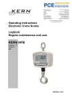
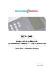
PCE Americas Inc.
711 Commerce Way
Suite 8
Jupiter
FL-33458
USA
From outside US: +1
Tel: (561) 320-9162
Fax: (561) 320-9176
info@pce-americas.com
PCE Instruments UK Ltd.
Units 12/13
Southpoint Business Park
Ensign way
Hampshire / Southampton
United Kingdom, SO31 4RF
From outside UK: +44
Tel: (0) 2380 98703 0
Fax: (0) 2380 98703 9
info@pce-instruments.com
www.pce-instruments.com/english
www.pce-instruments.com
Manual
Hand-held Ultrasonic Flow Meter
PCE-TDS 100H/HS
Manual
Version 1.0
17.07.2015
Table of contents
1
Introduction ............................................................................................................. 4
1.1
General ....................................................................................................................................... 4
1.2
Features...................................................................................................................................... 4
1.3
Typical applications .................................................................................................................... 5
1.4
Data integrity and integrated timekeeper ................................................................................... 5
2
Safety information ................................................................................................... 5
3
Specifications .......................................................................................................... 6
4
Device description .................................................................................................. 7
5
Instructions.............................................................................................................. 8
5.1
5.1.1
5.1.2
5.1.3
5.1.4
5.1.5
5.1.6
5.1.7
5.1.8
5.1.9
Preparation before measurement ............................................................................................... 8
Internal battery ............................................................................................................................... 8
To switch on the device ................................................................................................................. 8
Keypad ........................................................................................................................................... 9
Menu windows ............................................................................................................................... 9
Arrangement of menu windows ................................................................................................... 10
Parameter configuration ............................................................................................................... 10
Installation of the sensor fixings ................................................................................................... 11
Sensor installation ........................................................................................................................ 12
Installation checkup...................................................................................................................... 13
5.2
5.2.1
5.2.2
5.2.3
5.2.4
5.2.5
5.2.6
5.2.7
5.2.8
5.2.9
5.2.10
5.2.11
5.2.12
5.2.13
5.2.14
5.2.15
5.2.16
5.2.17
5.2.18
5.2.19
5.2.20
5.2.21
5.2.22
5.2.23
5.2.24
5.2.25
5.2.26
5.2.27
5.2.28
How to use the device .............................................................................................................. 14
To find out whether the device works properly ............................................................................ 14
To recognise the flow direction .................................................................................................... 15
To switch between unit systems .................................................................................................. 15
To switch flow units ...................................................................................................................... 15
To set the multiplier of the totaliser .............................................................................................. 15
To switch the totaliser on and off ................................................................................................. 15
To reset the totaliser .................................................................................................................... 15
To reset the meter to default settings .......................................................................................... 15
To use the damping function ........................................................................................................ 15
To use the minimum value function ............................................................................................. 15
To set the zero point .................................................................................................................... 15
To determine the calibration factor .............................................................................................. 16
To use the lock function ............................................................................................................... 16
To use the datalogger .................................................................................................................. 16
To use the output signal ............................................................................................................... 16
To use the totaliser pulse output .................................................................................................. 16
To use the alarm function ............................................................................................................ 17
To use the beeper ........................................................................................................................ 17
To use the OCT output ................................................................................................................ 17
To set the date ............................................................................................................................. 17
To adjust the display contrast ...................................................................................................... 17
To set the RS-232 interface ......................................................................................................... 17
To view the date totaliser ............................................................................................................. 17
To use the timer ........................................................................................................................... 17
To use the manual totaliser .......................................................................................................... 18
To check the serial number and other details .............................................................................. 18
To check the battery life ............................................................................................................... 18
To charge the battery ................................................................................................................... 18
2
Manual
5.3
The menus ................................................................................................................................ 18
5.4
5.4.1
5.4.2
5.4.3
Troubleshooting ........................................................................................................................ 21
Error messages when switching on ............................................................................................. 21
Error codes and counter-measures ............................................................................................. 21
Other errors and solutions ........................................................................................................... 22
5.5
5.5.1
5.5.2
Interface protocol ...................................................................................................................... 22
Pin functions ................................................................................................................................. 22
Protocol ........................................................................................................................................ 23
6
Maintenance .......................................................................................................... 24
7
Batteries ................................................................................................................. 24
8
Disposal ................................................................................................................. 24
9
Contact ................................................................................................................... 25
9.1
PCE Instruments UK ................................................................................................................ 25
9.2
PCE Americas .......................................................................................................................... 25
3
Manual
1
Introduction
1.1
General
Thank you for purchasing a PCE-TDS 100H/HS hand-held ultrasonic flow meter from PCE Instruments.
This flow meter can be used for metallic, plastic and rubber tubes. It is very easy to install, use and
ensures high accuracy and outstanding reliability. It has a very user-friendly interface. Due to the patent
technology, interferences (e. g. through power frequency) are nearly eliminated which makes this device
work properly even in demanding industrial environments. Another outstanding feature is that the
transducers / sensors automatically adapt the signal strength so that the user does not have to make any
adjustments. Furthermore, rechargeable Ni-H batteries make sure that the device can be used
continuously for more than 10 hours without recharging.
This meter measures the flow velocity of a liquid within closed pipes. It works on the basis of the transittime difference method. The difference between the flow time in the flow direction and the flow time
against the flow direction directly depends on the flow velocity. In case of a diagonal measurement, the
tube will need less time in the same flow direction than against the flow direction. When the flow
increases, you will need more time for the flow measurement if the measurement is against the flow
direction and less time if the measurement is in the same flow direction. To measure the flow velocity,
electroacoustic transducers receive and send out short ultrasonic pulses through the liquid that flows
through the pipe. The transducers are placed offset alongside both sides of the measuring tube. The nondestructive sensors must be placed on the pipe and fastened e. g. with a cable tie. The display will soon
indicate the flow velocity.
ᶿ
M
D
Tup
Tdown
Delta T
angle to flow direction
time
diameter of the pipe
time for the beam from downstream transducer to upstream transducer
time for the beam from upstream transducer to downstream transducer
Tup - Tdown
1.2
Features
linearity 0.5 %
reproducibility 0.2 %
bilingual interface
several integrated totalisers
patent ultrasonic sensors
interfering frequencies are eliminated
high-precision time measurements
date function
datalogger
adjustable response time
4
Manual
1.3
Typical applications
The PCE-TDS 100H/HS flow meter can be applied to a wide range of measurements. The pipes can
have a diameter of between 50 and 700 mm. There are no special requirements regarding the liquid to be
measured. It can measure ultra-pure water, potable water, chemicals, raw sewage, cooling water, river
water etc. Since the sensors are placed on the pipe from outside and do not have any moving parts, they
are not subject to any wear and tear. Moreover, the pressure of the liquid and the pH value do not affect
the meter. The standard measuring heads can be used for temperatures of up to +70 °C. Sensors for
higher temperatures are available at PCE Instruments.
1.4
Data integrity and integrated timekeeper
All values and configurations entered by the user are saved permanently via the internal non-volatile
memory, even after power has been interrupted. Password protection remains.
The meter is equipped with an internal clock which goes as long as the voltage is more than 1.5 V. In
case voltage is below that value, the internal clock will not go and must be set manually later. Wrong time
information does not affect the function of the meter negatively. However, the total operating hours will be
incorrect.
2
Safety information
Please read this manual carefully and completely before you use the device for the first time. The device
may only be used by qualified personnel and repaired by PCE Instruments personnel. There is no
warranty of damages or injuries caused by non-observance of the manual. The device is subject to
common norms and standards and is
certified.
- Before putting into service, the device must be stabilized to ambient temperature (important when taking
from cold to warm or from warm to cold rooms)
- The device may only be used in approved humidity and temperature range:
ambient humidity max. <80 % RH
ambient temperature range 0 … +70 °C
- Exposure to extreme temperatures, direct sunlight, extreme moisture or wetness (e. g. wet hands) must
be avoided
- Use the flow meter only inside buildings or outside if ambient condition is dry
- The appliance must not be used in atmospheres within the reach of corrosive or explosive gases
- Avoid strong shocks
- To avoid damage to the meter, only make measurements which are within and if possible not at the limit
of the measurement ranges
- Always observe the warning symbols
- The case may only be opened by qualified personnel of PCE Instruments
- Remove all test leads you do not wish to use from the device
- Connect the test leads to the meter first and then to the object to be measured
- Position the test leads carefully
- The instrument should never be placed with the user interface facing an object (e.g. keyboard side on a
table)
- You must not make any technical changes to the device
- The appliance should only be cleaned with a damp cloth / use only pH-neutral cleaner
This user manual is published by PCE Instruments without any guarantee.
We expressly refer to our general guarantee terms, they can be found in our general terms of business.
If you have any questions please contact PCE Instruments.
5
Manual
3
Specifications
Linearity
Repeatability
Resolution
Accuracy
Response time
Measuring range
Pipe size
Rate units
Totalizer
Cable length
Liquid types
Security
Display
Communication interface
Power supply
Net adaptor
Datalogger
Case material
Case size
Working condition
Weight
0.5 %
0.2 %
0.0001 m/s
1 % of reading
0-999 seconds, user-configurable
0.01 … 30 m/s
20 mm – 100 mm type S1
50 mm – 700 mm type M1
meters, feet, cubic meters, liters, cubic feet,
USA gallons, imperial gallons, oil barrels, USA
liquid barrels, imperial liquid barrels, million
USA gallons
7-digit for net, positive and negative flow
respectively
5.00 m
all liquids
can be locked so that no changes can be made,
with access code
4 x 16 LCD
RS-232 C
3 x AAA Ni-H rechargeable battery
100 … 240 V/AC
can store 2000 sets of data
ABS
100 x 66 x 20 mm
0 … 70°C
514 g with batteries
6
Manual
4
Device description
Converter:
7
Manual
5
5.1
Instructions
Preparation before measurement
5.1.1 Internal battery
The instrument can either be powered by the internal rechargeable battery (which lasts more than 10
hours of continuous operation) or by the power supply unit.
The battery charging is controlled with constant power and constant voltage. The battery is charged
quickly at the beginning and very slowly when the battery is almost fully charged. Generally, the battery is
approx. 95 % charged when the green LED glows and when the red LED goes off, the battery is 98 %
charged. When the battery is almost fully charged, the charging rate gets smaller. This is to avoid that the
battery is overcharged. If you want to use the device 24/7, you can keep it connected to the power supply
system all the time.
When the battery is fully charged, it has a voltage of 4.25 V. The voltage is displayed in the window M07.
The battery is almost flat when its voltage is lower than 3 V. The device also indicates the remaining
battery life which is determined internally by means of the voltage. However, this value should only serve
as an approximate information.
5.1.2 To switch on the device
Press the ON key to switch on the device and the OFF key to switch it off. Once the flow meter has been
switched on, it will run a self-diagnostic program, testing the hardware and the internal software. In case
the device detects an error, this error will be shown in the display.
8
Manual
Generally, no error message should appear. The device then shows the most commonly used window
M01 which displays velocity, flow, the totaliser, signal strength and signal quality, based on the values of
the pipe which have been last set.
The internal flow measurement programme always operates in the background of the interface, which
means that measurements take place all the time, regardless of which window is open. Only if you enter
new parameters for the pipe to be measured, the meter will operate with the new values.
When you have entered new parameters or switch on the device, an adjustment programme will adjust
the signal enhancement to determine which setting is best to receive the signals. This process is shown
to the user by displaying the numbers 1, 2 and 3 on the lower right-hand side of the display.
When you adjust the sensors to the pipe, the meter will automatically adjust the signals. Your values
remain in the memory of the device until you change them.
5.1.3
Keypad
The keypad consists of 16
+ 2 keys. The keys 0 to 9
and the decimal point are
there to enter numbers.
The Up and Down keys are
used to switch windows. In
the case of numbers, these
keys also serve as plus
and minus.
The Back Space key
serves to go a space back
or to move the cursor left.
ENT is the Enter key to
confirm or select.
With the MENU key, you
can go directly to the menu
window. If you want to go
to a certain window, you
can press the respective
two numbers after pressing
the MENU key.
The ON and OFF keys are
used to switch the device
on and off.
5.1.4 Menu windows
The device comprises approx. 100 different menu windows which are numbered M00, M01,
M02, M03...M99.
There are two methods to select these windows:
(1) directly by pressing the
M11.
key and two numbers (digits), for example
and
for menu window
(2) by pressing the
and
keys. Whenever you press one of these keys, the next or last window will
appear. For example, when you are in window M00, you have to press the Down key to get to the next
window.
9
Manual
The device has three different types of windows:
(1) window to enter numbers, e. g. M11 to enter the pipe diameter.
(2) window to select options, e. g. M14 to choose the material of the pipe.
(3) windows that only display data and do not allow to enter data, e. g. M100 to show velocity, flow, …
When you are in a window to enter numbers, you can directly enter data and confirm with Enter. If you
are in window M11, you can directly enter the outer pipe diameter by pressing
In a window to select options, you must always press the
key first and then choose the selection with
the
or
key or with the number keys if the device requires a number. Then confirm the selection
with the
key, e. g. the window M14 to choose the material. Press
to select the window.
Stainless steel, for example, is allocated the number 1. To choose other materials, you must first press
the
key. Only after doing so, you can make a selection with the
keys and confirm with the
key. Another possibility would be to choose the selection directly via the number pad.
Generally, the
key must be pressed whenever you want to confirm a change. However, when you
see, for example, the message “Locked M47 Open“ on the lower side of the display, this means that this
function is disabled. In this case, you must go to window M47 before you can make settings.
5.1.5 Arrangement of menu windows
M00 ... M09 windows for volume flow, velocity, date, time, totaliser, battery voltage, remaining battery
life
M10 ... M29 window for parameters of the pipe
M30 ... M38 windows to select the units
M40 ... M49 windows for response time, zero adjustment, calibration and password protection
M50 ... M53 windows for the datalogger
M60 ... M78 windows for date and time setting, displays the software version and serial number
M82
window for total operating hours
M90 ... M94 diagnostic windows
M97 ... M99 no windows but commands for the display and pipe setup
M+0 … M+8 windows for further functions, including a scientific calculator, outlines about the operating
hours, switch-on and switch-off times …
Some windows are not active anymore, e. g. the window M88. This window has been disabled in line with
a software update. The main reason why the windows have been arranged this way is that it is possible to
add new functions in line with a software update and thus to keep the device future-proof.
5.1.6 Parameter configuration
To ensure accurate measurement values, enter the following data into the device:
(1) Outer diameter of the pipe
(2) Material thickness of the pipe
(3) Material of the pipe (there is no standard material for which you must enter the transmission speed of
sound [m/s]). Standard pipe materials and standard liquids refer to the parameters which have already
been programmed into the software, so there is no need to configure them.
(4) If the pipe is lined, the speed of sound (of the material) and the thickness of the coating are needed as
well.
(5) Type of liquid (there is no standard liquid for which the speed of sound is needed)
(6) Type of connected sensors, which is normally Standard ML or sensors with frame size M.
(7) Sensor arrangement (V or Z method is standard)
(8) Check the distance displayed in menu M25 and fasten the sensors accordingly.
For standard pipe materials and standard liquids, certain steps are recommended, as described in detail
in the following
(1) Go to menu M11 and press the
key to be able to make a selection. With the number keys, you
choose the diameter of the pipe and confirm with
.
10
Manual
(2) Enter menu M12 by pressing
and press
to be able to make a selection. With the number keys,
you choose the material thickness of the pipe and confirm with
.
(3) Enter menu M14 by pressing
and press
to be able to make a selection. With the keys
, you choose the material of the pipe and confirm with
.
and
(4) Enter menu M16 by pressing
and press
to be able to make a selection. With the keys
and
, you choose the material of the inner liner of the pipe. If there is no liner, select “No Liner“ and confirm
with
.
(5) Enter menu M20 by pressing
and press
, you choose the liquid and confirm with
.
to be able to make a selection. With the keys
and
(6) Enter menu M23 by pressing
and press
to be able to make a selection. With the keys
, you choose the type of the sensors and confirm with
.
and
(7) Enter menu M24 by pressing
and press
to be able to make a selection. With the keys
, you choose the arrangement method of the sensors and confirm with
.
(8) Enter menu M25 by pressing
and place the sensors on the pipe, considering the displayed
distance and then press the
key. In menu M01, you can see the measurement values.
and
Using the meter for the first time can take a while. Get familiar with the device. The user-friendly interface
makes it easy and simple to use the device. Via the Menu keys, the user can quickly get to the right menu
without any further steps.
The following steps are meant to make the use easier for you:
(1) When you are between menu window M00 and M09, you must only press a number X to get to
another (one-digit) M0X window. For instance, when you are in window M09, you only need to press 4 to
immediately get to window M04.
(2) When you are between menu window M00 and M09, you can go directly to M90 by pressing
. To
go back, press
again. By pressing the decimal point key, you can go directly to M11. When you are
below M25, you can go directly to M01 by pressing
.
5.1.7
Installation of the sensor fixings
The first step in the installation process is to find a suitable position for the sensor fixings in order to
ensure an accurate measurement. For this purpose, it is advisable to gain some knowledge about fluid
mechanics (in pipes).
An optimum position would be an endlessly long straight pipe with no air bubbles in the liquid. The piping
can run vertically or horizontally. To avoid inaccuracies due to turbulence in the liquid, straight flowcalming sections in front of and behind the measuring point should be considered. In front of the
measuring point, it should generally be 10 times as long as the diameter of the pipe and behind the
measuring point, it should be 5 times as long as the diameter of the pipe.
The following chart shows examples of good positions:
11
Manual
Principles for good measuring points:
(1) Install the sensors on a straight pipe which is as long as possible and which is completely filled with
liquid without any air bubbles.
(2) Make sure that the liquid and thus the pipe is not too hot for the sensors. The closer the temperature
is to the ambient temperature, the better.
(3) Take dirt on the pipes into consideration. Measure a clean or newer pipe, if possible. If it is not
possible to clean the pipe, calculate the thickness of the dirt in relation to the case of the pipe.
(4) Some pipes have a kind of plastic liner. Between the outer pipe and the inner liner, there may be a
boundary layer which might divert or weaken the ultrasonic waves, what makes a measurement very
difficult. If possible, try to avoid this kind of pipes. If not, you can install a built-in sensor to the pipe.
5.1.8 Sensor installation
The sensors of the PCE-TDS 100H/HS are piezo-electric and suitable for transmitting and receiving
ultrasonic waves. The time the ultrasonic waves take to flow through the pipe walls and through the liquid
allows conclusions about the flow velocity. Since the transit time of the ultrasonic pulses is very short, you
must place the sensors as exactly as possible, taking the distance and the position into account, to
ensure accuracy of the system.
Take the following steps to install the sensors:
(1) Find the optimum position in your pipe system, i. e. a straight run with preferably new, clean pipes.
(2) As it is very important that the pipes are clean, grind and polish the positions where you wish to place
the sensors.
(3) Between the sensors and the pipe surfaces, there must not be any gap. Install the sensors with
sufficient coupling gel.
Furthermore, you must make sure that there is no dust or sand between the pipes and the sensor. To
avoid air bubbles in the liquid which can cause faulty measurements, place the sensors to the side of the
pipe.
12
Manual
5.1.8.1 Sensor distance
The inner distance between the two sensors, which can be found in window M25, should be observed as
accurately as possible.
5.1.8.2 V method installation
The V method is the most common method for day-to-day measurement. It is ideal for inner pipe
diameters of between 20 and 300 mm. It is also called the reflective method.
5.1.8.3 Z method installation
The Z method is recommended when the pipe diameter is between 300 and 500 mm.
5.1.8.4 W method installation
The W method is advisable when you have plastic pipes with a diameter between 10 and 100 mm.
5.1.8.5 N method
This method is rarely used.
5.1.9 Installation checkup
By means of a checkup, the user can check the following: the signal input strength, the signal quality [Q],
the time difference of the signals, the estimated velocity, the transit time of the signals as well as the
13
Manual
calculated time ratio. This improves the measurement results and increases the operating time of the
device.
5.1.9.1 Signal strength
The strength of the acoustic signals is indicated by a 3-digit number. [000] means that no signal has been
detected whereas [999] indicates maximum signal strength. Although the device works well with signal
strengths between 500 and 999, the signal strength should be as high as possible. The following methods
are recommended to obtain stronger signals:
(1) Relocate the sensors to a more favourable position in the pipe system so that the signal strength is
higher than 700.
(2) Try polishing the surface of the pipe and use enough coupling gel between the pipe wall and the
sensor.
(3) Adjust the sensors both horizontally and vertically and watch the signal strength. After doing so, you
should check the sensor distance again to make sure it is the same as stated in M25.
5.1.9.2 Signal quality
The PCE-TDS 100H/HS indicates the signal quality Q. A higher Q value means that the Signal and Noise
Ratio (SNR) is higher and accordingly that the accuracy is higher. Under normal conditions, the Q value
should be between 60 and 90, the higher the better. Possible reasons for a lower Q value include:
(1) Interference by other instruments and devices. Try removing or switching off the other instruments and
devices or find an alternative measuring point.
(2) Poor coupling between the sensor and the wall. Clean the surfaces and use coupling gel.
(3) The pipe condition is poor. Relocation is recommended.
5.1.9.3 Transit time and delta time
The values in window M93 are called total transit time and delta time. They are the raw data the device
needs to calculate the flow velocity in the pipe. Accordingly, the indication of the flow velocity varies with
the transit time and delta time.
The transit time should be relatively steady and change only slightly. If the delta time fluctuates by more
than 20 %, it is likely that there is a problem with the sensor installation.
5.1.9.4 Time ratio between transit time and calculated time
This time ratio serves to review the sensor installation. If the pipe data have been entered correctly and th
sensors have been installed properly, the ratio should be about 1003. If this value has been exceeded,
check the following:
(1) Have the pipe parameters been entered correctly?
(2) Has the distance of the sensors been set correctly as indicated in M25?
(3) Have the sensors been placed in the right direction and connected to the device properly?
(4) If the place of installation is ok and if the shape of the pipe has not changed, it is possible that the
inside of the pipe is covered with dirt or moss.
(5) Other poor conditions?
5.2
How to use the device
5.2.1 To find out whether the device works properly
If an “R“ is displayed in the lower right-hand corner, the device should work properly.
If an “H“ flashes, this could indicate a poor signal. Refer to the chapter “diagnosis”.
If an “I“ is displayed, this means that no signal is detected.
If a “J“ is displayed, this means that the hardware is defective. Refer to chapter “diagnosis”.
14
Manual
5.2.2 To recognise the flow direction
(1) Make sure that the device works properly.
(2) Check the indication of volume flow. If the value is positive, the flow direction is from the red to the
blue sensor. If the value is negative, the flow direction is from the blue to the red sensor.
5.2.3 To switch between unit systems
Use window M30 to switch from the metric to the English system.
5.2.4 To switch flow units
In window M31 you can set flow unit and time unit. Start by choosing the flow unit and then select the
time unit.
5.2.5 To set the multiplier of the totaliser
Use window M33 to set the multiplier of the totaliser. Make sure that the multiplier is set in an appropriate
relation to the volume flow expected. It should be neither too high nor too low. The ideal setting is the one
in which a pulse is generated every few seconds or minutes.
If the multiplier is too low, pulses can get lost as there are at least 500 milliseconds between two pulses.
If the multiplier is too high, the output pulses get too rare. This can lead to problems if the evaluation units
are quick.
5.2.6 To switch the totaliser on and off
Use the windows M34, M35 and M36 respectively to switch the positive, negative and net totaliser on and
off.
5.2.7 To reset the totaliser
Use the window M37 to reset the totaliser.
5.2.8
To reset the meter to default settings
Use the menu M37 when “selection” is displayed. Press the
key first. “Master Erase” will now be
displayed. Press the
key. All values will be reset to factory defaults now.
5.2.9 To use the damping function
The damping function works like a filter to stabilise reading. If the value in window M40 is “0”, there is no
damping. A higher value stabilises reading, however, the device works more slowly. Normally, a value
between 0 and 10 is set.
5.2.10 To use the minimum value function
The number in window M41 is called minimum value. All values under this value are displayed by the
device as “0”. This means that “outliers” are not taken into consideration. The minimum value does not
affect the flow measurement itself as long as the actual velocity is above this minimum value.
5.2.11 To set the zero point
It is possible that the device displays a value even though there is no flow. In this case, you can use
window M42 to set a zero point. It is important that the flow in the pipe is stopped. Then press the
key.
15
Manual
5.2.12 To determine the calibration factor
The calibration factor is a value between the actual flow velocity and the flow velocity indicated by the
meter. This factor can be determined by carrying out a calibration. However, this can only be done by
means of complex calibration equipment.
5.2.13 To use the lock function
The system can be locked to prevent unintentional configuration changes. When the device is locked, you
can click through all windows but you cannot make any changes.
You can lock the device with or without a four-digit password. If you have not set a password, press the
key when you are asked for the password. Otherwise, enter the four-digit number. If you have
forgotten your password, please contact PCE Instruments.
5.2.14 To use the datalogger
The device has an internal memory of 24k bytes which can save 2000 values.
With window M50, you turn on the logger and choose the values to be saved.
With window M51, you set start time, saving intervals and end time.
With window M52, you determine the memory location. The data is saved to the device by default. It is
also possible to save the data directly in the RS-232 data interface without saving them to the internal
memory.
Via window M53, you can view the saved data.
By means of the functions in window M52, you can read the saved data via the RS-232 interface and
delete the internal memory.
5.2.15 To use the output signal
The device is equipped with a signal output which can be connected to other devices. The output signal
indicates the flow velocity and can be freely configured. Generally, four parameters should be set. Enter
the lowest flow in window M68 and the highest flow in window M69. Then, enter the frequency range in
window M67.
For instance, if the volume flow is between 0 and 3000 m³/h and the output frequency is between 200 Hz
and 1kHz, enter “0” in window M68, “3000” in window 69 and 200 to 1000 Hz in window M67.
Please note that you must set the OCT (Open Collect Transistor output) in window M78. Here you can
choose option 13 “FO output” to send the frequency directly to the output.
5.2.16 To use the totaliser pulse output
The totaliser pulse output creates a pulse at each flow unit.
The OCT output or the buzzer can also be used as a pulse output.
Example:
When the pulse output is needed for the positive sum counter and each pulse represents a volume flow of
0.1 m³, the pulse is passed on to the buzzer. An acoustic signal is emitted at each volume flow of 0.1 m³.
The following settings must be made:
(1) Choose cubic metres [m³] as the unit in window M32.
(2) Choose “2. XO.1” as the multiplier in window M33.
(3) Choose the output “9. POS INT Pulse” in window M77. (INT means “integrating totaliser”)
16
Manual
5.2.17 To use the alarm function
There are two types of alarm signals available. One is via the beeper and one is via the OCT output?
The following applies to both options:
(1) Alarm is triggered when no signal is received
(2) Alarm is triggered when the signal is poor
(3) Alarm is triggered when the device is not in normal measuring mode
(4) Alarm is triggered when the flow direction is incorrect
(5) Alarm is triggered when the flow velocity is too high for the set output frequency
(6) Alarm is triggered when the flow is outside the set range
There are two alarms for a range that can be selected. They are called Alarm #1 and Alarm #2. You can
set the ranges via the windows M73, M74, M75 and M76.
For example, if you want to set an alarm that is triggered when the volume flow drops to less than 300
m³/h or increases to more than 2000 m³/h, the following settings are recommended:
(1) Enter 300 in window M73 for Alarm #1
(2) Enter 2000 in window M74 for Alarm #1
(3) To view the values, select “6. Alarm #1” in window M77.
5.2.18 To use the beeper
The beeper can be configured via window M77.
5.2.19 To use the OCT output
You can configure the OCT output via the window M78.
THE OCT output occupies two pins of the RS-232 interface: PIN 6 for the signal and PIN 5 for the ground.
5.2.20 To set the date
In most cases, the date does not have to be set. The internal calendar even runs when voltage is low. It is
only necessary to set the date when the battery is completely flat or when a battery replacement takes
longer.
Press the
key in window M61 to get to the mode in which you can make settings. Use the
get to the numbers you wish to set.
key to
5.2.21 To adjust the display contrast
Go to menu M70. The setting is saved in the non-volatile memory and thus remains available
permanently.
5.2.22 To set the RS-232 interface
Go to menu M62.
5.2.23 To view the date totaliser
Use menu M82 to view the value of the date totaliser which contains a day totaliser, a month totaliser and
a year totaliser.
5.2.24 To use the timer
You can use the timer to determine how long a certain measurement has taken. For instance, you can
read how long a full battery lasts.
17
Manual
You can go to window M72 to reset the timer by means of the
key.
5.2.25 To use the manual totaliser
Use window M28 to start and stop the manual totaliser.
5.2.26 To check the serial number and other details
Each meter has an Electronic Serial Number (ESN) that can be clearly identified. This is an 8-digit
number which identifies the version and the production date and can be found in window M61.
Further information about the device are the total operating hours in window M+1 and the total time the
device has been switched on in window M+4.
5.2.27 To check the battery life
Go to window M07 to get information about the battery.
5.2.28 To charge the battery
Use the PSU.
5.3
The menus
Menu window no.
M00
M01
M02
M03
M04
M05
M06
M07
M08
M09
M10
M11
M12
M13
M14
M15
M16
M17
M18
Function
Displays three totalisers (positive, negative and net), signal strength, signal quality
and working status
Displays the positive totaliser, volume flow, velocity, signal strength, signal quality
and working status
Displays the negative totaliser, volume flow, velocity, signal strength, signal quality
and working status
Displays the net totaliser, volume flow, velocity, signal strength, signal quality and
working status
Displays time and date, volume flow, signal strength, signal quality and working
status
Displays time and date, velocity, signal strength, signal quality and working status
Displays the wave shape of the received signal
Displays battery voltage and remaining battery life
Displays all working modes in detail, signal strength and signal quality
Displays up-to-date volume flow, velocity, signal strength, signal quality and
working status
Window to enter outer perimeter of the pipe
Window to enter outer diameter of the pipe. 0 to 6000 m are allowed
Window to enter material thickness of the pipe
Window to enter inner diameter of the pipe
Window to select standard pipe material (if your material is listed here you do not
need the speed of sound):
0. steel, 1. stainless steel, 2. cast iron, 3. spheroidal graphite iron, 4. copper, 5.
PVC, 6. aluminium, 7. asbestos, 8. fiberglass
Window to enter the transmission speed of sound of the pipe material – only
necessary for non-standard materials
Window to select the inner liner. If the pipe does not have a liner, select “0. No
Liner”.
1. epoxy resin, 2. rubber, 3. mortar, 4. polypropylene, 5. PS, 6. polystyrene, 7.
polyester, 8. polyethylene, 9. ebonite, 10. Teflon
Window to enter the transmission speed of sound of the inner lining material – only
necessary for materials not listed in M16
Window to enter material strength and inner liner
18
Manual
M19
M20
M21
M22
M23
M24
M25
M26
M27
M28
M29
M30
M31
M32
M33
M34
M35
M36
M37
M38
M39
M40
M41
M42
M43
M44
M45
M46
M47
M48
M49
M50
M51
Window to enter absolute thickness of the inner wall
Window to select the standard liquid:
0. water, 1. sea water, 2. paraffin, 3. petrol, 4. fuel oil, 5. naphtha, 6. propane, 7.
butane, 8. other liquids, 9. diesel oil, 10. castor oil, 11. peanut oil, 12. Q90 petrol,
13. Q93 petrol, 14. alcohol, 15. hot water at 125 °C
Window to enter the transmission speed of sound of the liquid – only necessary for
non-standard liquids
Window to enter viscosity of the liquid - only necessary for non-standard liquids
Window to select the sensors. You can choose from 14 types. Standard type is
PCE TDS-M1
Window to select sensor installation:
0. V method, 1. Z method, 2. N method, 3. W method
Window to display sensor distance which you should stick to as exactly as
possible
To save parameters to the internal memory
To retrieve the save parameters
Select YES or NO to determine whether you want the device to keep the last good
value or not when the signal is poor. The standard setup is YES
Select a measurement range between 0 and 999, while 0 is the standard setting
Window to select a unit system: metric or English
Window to select the unit:
0. cubic meter
[m³]
1. litre
[l]
2. USA gallon
[gal]
3. imperial gallon
[igl]
4. million USA gallons
[mgl]
5. cubic feet
[cf]
6. USA liquid barrel
[bal]
7. imperial liquid barrel
[ib]
8. oil barrel
[ob]
The time can be per day, per hour, per minute and per second.
Thus, you can choose between 36 different units
Window to select the working unit of the totaliser
Window to select the multiplier for the totaliser between 0.001 and 10000
To switch the net totaliser on and off
To switch the positive totaliser on and off
To switch the negative totaliser on and off
1. To reset the totaliser
2. To reset the device to factory defaults by pressing the
key and then the
key. Be careful with this function and write down your individual settings before
using it
Press a key to start or stop the totaliser for easier calibration
To change the language (English or Chinese)
Window to set the damping between 0 and 999 seconds. When “0” is selected,
there is no damping
Window to set minimum value
Window to set zero adjustment. Make sure that there is no liquid running through
the pipe
Deletes your zero point and goes to the zero point set by the factory
Sets a flow value by hand (an offset value), which should be “0” under normal
conditions
Scaling factor for calibration. This value should be “1” unless your device has been
calibrated already
Network identification number
Window to lock the device which locks the possibility to change parameters
Not used
Interface test
Window for datalogger
Time settings for the logger
19
Manual
M52
M53
M54
M55
M56
M57
M58
M59
M60
M61
M62
M63
M64
M65
M66
M67
M68
M69
M70
M71
M72
M73
M74
M75
M76
M77
M78
M79
M80
M81
M82
M83
M84
M85
M86
M87
M88
M89
M90
M91
1. The data are saved to the internal memory as well as transferred to the RS-232
interface
2. The data are saved to the internal data memory only
3. The data are transferred to the RS-232 interface and the internal memory is
deleted
Window to view the saved data in the internal memory. You can browse through
the data by using the keys
, ,
and
. When the logger is active, the
indication is refreshed automatically
Not used
Not used
Not used
Not used
Not used
Not used
Calendar for 99 years. Press the
key for changes. You can skip data by
pressing
.
Window to display software version and serial number (ESN)
Window to set the RS-232 interface, baud rates of 75 to 115200bps are possible
Not used
Not used
Not used
Not used
To select the frequency range for the output between 0 and 9999 Hz. 1 to 1001 Hz
is the default setting
To set the volume flow for the lowest frequency
To set the volume flow for the highest frequency
Display backlight. The value is the time in seconds for how long the backlight is on
without pressing any key
To set the display contrast
To reset the operating hours counter, press
and confirm with YES
To enter the lower limit that will trigger Alarm #1. There are two alarms. You can
set the alarm via M78 and M79
To enter the upper limit that will trigger Alarm #1
To enter the lower limit that will trigger Alarm #2
To enter the upper limit that will trigger Alarm #2
To set the buzzer / beeper
If the correct input has been selected, the beeper chimes whenever an alarm is
triggered
OCT (Open Collect Transistor output)
If the correct input has been selected, the OCT transmits a signal whenever an
alarm is triggered
Not used
Serves as a keypad and display for another hand-held device connected via the
RS-232 interface
Not used
Date totaliser
Not used
Not used
Not used
Not used
Not used
Not used
Not used
Display shows signal strength, signal quality, transit-time difference in the upper
right-hand corner
Display shows the time ratio between the measured transit time and the calculated
transit time. If all pipe parameters have been entered correctly and the sensors
have been installed correctly, the ratio should be somewhere around 100 % ± 3 %.
20
Manual
M92
M93
M94
M95
M96
M97
M98
M99
M+0
M+1
M+2
M+3
M+4
M+5
M+6
M+7
M+8
M+9
M-0
5.4
If this is not the case, check all parameters as well as the sensor installation
Displays the estimated transmission speed of sound. If there is a substantial
difference to the actual transmission speed of sound, check all parameters and the
sensor installation
Displays the total transit time and delta time (transit time difference)
Displays the Reynolds number and the pipe factor used by the device
Not used
Not used
Command to save the entered pipe parameters, either to the internal datalogger or
via the RS-232 interface
Command to save the diagnostic information, either to the internal datalogger or
via the RS-232 interface
Command to save the current display, either to the internal datalogger or via the
RS-232 interface
To view the 64 sets of data (date when device has been switched on and off and
time of flow measurement)
Displays the total operating hours of the device
Displays the time and date of last switch-off
Displays the last volume flow before last switch-off
Displays the time of last switch-on
Scientific calculator (complicated use)
Not used
Not used
Not used
Not used
Window with access to hardware adjustment, for the manufacturer only
Troubleshooting
5.4.1 Error messages when switching on
The device runs a self-diagnostic programme to find hardware errors when switched on. The following
chart indicates error messages that might occur and solutions.
error message
reason
measures
ROM Testing Error
software problem
(1) Switch the device on again
Segment Test Error
(2) Contact the PCE Group
Stored Data Error
parameters entered by the user
Press the
key. All values are
are not integrated
reset to default
Timer Slow Error
problems with the timer
(1) Switch the device on again
Timer Fast Error
(2) Contact the PCE Group
Date Time Error
number error with the calendar
Set the calendar again via M61
Reboot repetitively
hardware problem
Contact the PCE Group
5.4.2 Error codes and counter-measures
Error codes are displayed by the device as only one letter on the lower right-hand side of the display.
Error messages are only displayed in the menus M00, M01, M02, M03, M90 and M08. The following chart
indicates error codes that might occur and solutions.
error code
message in window
reason
measures
M08
R
System Normal
no error
--I
Detect No Signal
(1) no signal
(1) Relocate measuring
(2) sensors installed
location
incorrectly
(2) Clean measuring
(3) to much moss or
location
dirt
(3) Check the cables
(4) liner of the pipe too
thick
21
Manual
J
Hardware Error
H
PoorSig Detected
Q
Frequ OutputOver
F
System RAM Error
Date Time Error
CPU or IRQ Error
ROM Parity Error
Adjusting Gain
1
2
3
K
(5) sensor cable not
connected properly
hardware problem
(1) no signal
(2) sensors installed
incorrectly
(3) to much moss or
dirt
(4) liner of the pipe too
thick
(5) sensor cable not
connected properly
frequency for output is
outside allowed range
(1) temporary problems
with RAM or RTC
(2) permanent
hardware problems
device is adjusting the
gain, the numbers
stand for the progress
(1) no liquid in the pipe
(2) setup error in menu
M29
Empty pipe
Contact the PCE
Group
(1) Relocate measuring
location
(2) Clean measuring
location
(3) Check the cables
(4) Check the coupling
gel
Review the values in
the windows M67, M68
and M69. Try entering
higher values in M69.
(1) Switch the device
on again
(2) Contact the PCE
Group
---
(1) Fill the pipe
(2) Enter “0” in menu
M29
5.4.3 Other errors and solutions
(1) If the device displays 0.0000 in spite of an existing volume flow and an “R” flashes in the display
and signal quality Q is ok, there must be another error. It is often the case that the zero point has
been set incorrectly. Go to menu M43 and reset the zero point.
(2) The volume flow displayed is clearly too low or too high:
a) It is very likely that a volume flow has been entered manually under M44. Adjust this value to
“0”.
b) Problems with the sensor installation
c) It is possible that the indication in menu M42 has been set to “0” even though a volume flow
exists. Set the value to “0” again and make sure that there is o flow in the pipe when you do
so.
(3) The battery life is shorter than stated in M07.
a) The battery has exceeded its life cycle.
b) The battery has not been fully charged or the charging process has been interrupted too
many times. Re-charge the battery. If the problem remains, contact the PCE Group.
c) When the battery voltage is between 3.70 and 3.90 V, the actual battery life may differ from
the estimated battery life.
5.5
Interface protocol
The PCE-TDS 100H/HS flow meter has an integrated RS-232C interface which can process a complete
set of communication protocols.
5.5.1 Pin functions
Pin 1 for battery charging, positive pole
Pin 2 RXD
Pin 3 TDX
Pin 4 not used
Pin 5 GND (ground)
22
Manual
Pin 6 OCT output
Pin 7 not used
Pin 8 for battery charging, negative pole
Pin 9 RING input to connect a modem
5.5.2 Protocol
The protocol consists of various basic commands in ASCII format. The following chart includes some
common commands.
command
DQD(CR)
DQH(CR)
DQM(CR)
DQS(CR)
DV(CR)
DI+(CR)
DI-(CR)
DIN(CR)
DID(CR)
DL(CR)
DT(CR)
M@(CR)***
OK(CR)
GA
function
return flow rate per day
return flow rate per hour
return flow rate per minute
return flow rate per second
return flow velocity
return POS totaliser
return NEG totaliser
return NET totaliser
return identification number
return signal strength and quality
return time and date
send a key value as if a key is
pressed
return the current window display
force the FO output with a
frequency in dddd Hz
return the ESN for the instrument
handshaking request by a
modem
response by a modem
command for GSM messaging
GB
GC
DUMP(CR)
DUMP0(CR)
DUMP1(CR)
command for GSM messaging
command for GSM messaging
return the buffer content
clear the entire buffer
return the entire buffer content
LCD(CR)
FOdddd(CR)
ESN(CR)
RING(CR)
W
N
P
&
Note:
*
**
***
prefix before an identification
number in a network
environment (the IDN is a word
ranging 0-65534)
prefix before an identification
number in a network
environment (the IDN is a single
byte value ranging 0-65534)
prefix before any command
command connector to make a
longer command by combining
up to 6 commands
CR stands for carriage return and LF for line feed
d stands for the 0 to 9 digit numbers
@ stands for the key value, e. g. 30 H for the “0” key
23
data format
± d.ddddd dE± dd(CR) (LF) *
± d.ddddd dE± dd(CR) (LF)
± d.ddddd dE± dd(CR) (LF)
± d.ddddd dE± dd(CR) (LF)
± d.ddddd dE± dd(CR) (LF)
± d.ddddd dE± d(CR) (LF) **
± d.ddddd dE± d(CR) (LF)
± d.ddddd dE± d(CR) (LF)
ddddd (CR) (LF)
S=ddd, ddd Q=dd (CR) (LF)
yy-mm-dd hh:mm:ss(CR) (LF)
ddddd (CR) (LF)
no action
please contact the PCE Group
for details
in ASCII string format
in ASCII string format
in ASCII string format, 24 KB in
length
Manual
6
Maintenance
Each meter has an Electronic Serial Number (ESN) written into the software that can only be modified by
the PCE Group by means of a special tool. In case of a malfunction or an error message, please state the
number which appears in the menu window M61 when contacting PCE Instruments.
7
Batteries
The Directive 2006/66/EC of the European Parliament and of the Council of 6 September 2006 includes
that due to the contained pollutants, batteries must not be disposed of as municipal waste. They must be
given to collection points designed for that purpose. You can also return them to PCE.
8
Disposal
For the disposal of batteries, the 2006/66/EC directive of the European Parliament applies. Due to the
contained pollutants, batteries must not be disposed of as household waste. They must be given to
collection points designed for that purpose.
In order to comply with the EU directive 2012/19/EU we take our devices back. We either re-use them or
give them to a recycling company which disposes of the devices in line with law.
If you have any questions, please contact PCE Instruments.
24
Manual
9
Contact
If you have any questions about our range of products or measuring instruments please contact PCE
Instruments.
9.1
PCE Instruments UK
By post:
PCE Instruments UK Ltd.
Units 12/13 Southpoint Business Park
Ensign Way, Southampton
Hampshire
United Kingdom, SO31 4RF
By phone:
02380 987 035
9.2
PCE Americas
By post:
PCE Americas Inc.
711 Commerce Way
Suite 8
Jupiter
33458 FL
USA
By phone:
561 320 9162
25