1
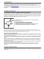
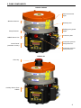
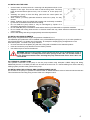
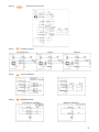
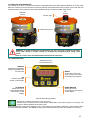
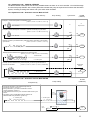
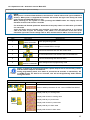
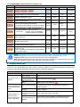
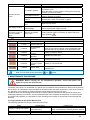
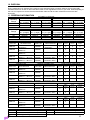
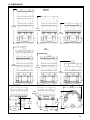
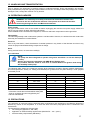
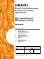
BRAVO Electric Lubrication pump for fixed and mobile applications User operation and Maintenance manual Warranty TABLE OF CONTENTS 1. 2. 3. 4. 5. 6. 7. 8. 9. 10. 11. 12. 13. 14. 15. 16. 17. 18. INTRODUCTION GENERAL DESCRIPTION PRODUCT IDENTIFICATION TECHNICAL CHARACTERISTICS PUMP COMPONENTS UNPACKING AND INSTALLING OPERATING INSTRUCTIONS TROUBLESHOOTING MAINTENANCE PROCEDURE DISPOSAL ORDERING INFORMATION DIMENSIONS HANDLING AND TRANSPORTATION OPERATING HAZARDS PRECAUTIONS WARRANTY DECLARATION OF COMPLIANCE WITH CE STANDARDS DISTRIBUTORS Manufacturer Product Year DropsA S.p.A. BRAVO 2008 Certification http://www.dropsa.com Manual drawn up in accordance with EC Directive 98/37, Annex I, paragraph 1.7.4 C2114IE - WK WK 37/08 1. INTRODUCTION This operation and maintenance manual refers to the Bravo lubrication pump, and includes essential information regarding correct operating and safety procedures design to ensure safe and reliable operation of the unit. You can obtain the latest release of this document by contacting a Dropsa sales office or distributor or by visiting us on the World Wide Web at http://www.dropsa.com. It is important that this document is read and maintained in a place that anyone operating the Bravo is able to consult it if necessary. 2. GENERAL DESCRIPTION http://www.dropsa.com 2.1 CENTRALIZED LUBRICATION – GENERAL OPERATING INFORMATION Centralized lubrication systems are designed to provide oil or grease for lubricating fiction points on industrial and mobile machinery. Such systems considerably reduce the cost of maintaining machinery on which they are installed, eliminating machinery downtime caused by poor lubrication as well as prolonging the life of the machinery in general. Additionally, a centralized lubrication system allows difficult to reach lubrication points to be lubricated at frequent intervals that would otherwise be hard to access under normal conditions. The diagram on the left shows a typical schematic of a simple centralized lubrication system. The main components are: A – Electric Pump with Reservoir (eg. Bravo Pump). B – Primary lubrication line for distributing grease. C – Distributor elements that meters grease into a number of points. D – Secondary tubing that delivers grease to the lube point. The pump feeds a distributor element that shares and doses the ratio of grease between the several friction points. Bravo Pump has been designed to provide the pumping solution for such systems used in industrial and mobile applications for greases up to NLGI 2 consistency and Oils with minimum 46cSt. 2.2 BRAVO ELECTRIC GREASE PUMP BRAVO is an electric piston pump with the pumping element operated from a camshaft connected to a reducing gearbox. It can be fitting with up to 3 Pumping elements (1 standard) which are available with or without an integrate pre-set bypass (pressure safety valve). The Bravo also has a modular build reservoir that can be supplied in 2, 5, 8 liter capacity. Additionally a minimum level sensing device is fitted as standard at the base of the unit. As an optional accessory, a remote button with light is available. Bravo is available as both with an integrated automatic control board that controls and monitors the pump and lubrication cycle or a manual version where the pump motor is controller externally by applying and removing power. The main body of the pump is made from high performance robust plastic and is compact in size designed to withstand tough environments. The grease version of the Bravo includes a stirrer device with a reservoir wiper that help to eliminate air present in the grease and facilitate pumping even at lower temperatures. The direct-current geared motor drive arrangement, is controlled remotely in the manual version or via the built in control system in the automatic version. There are three operating modes for the controller version. (Refer to 5.1 paragraph) 3. PRODUCT IDENTIFICATION On the side of the pump there is a label that indicates part number of the product, operating voltage and basic characteristics. 2 4. TECHNICAL CHARACTERISTICS GENERAL TECHNICAL CHARACTERISTICS AC DC AC - 50Hz AC - 60Hz Operating Voltage 12V 24V 12V 24V 110V 230V 110V 230V Current (nominal) 1A 0,5A 1A 0,5A 0,2A 0,1A 0,2A 0,1A Current (peak) 6,5A 3A 6,5A 3A 0,3A 0,2A 0,3A 0,2A 2 Liter 5,5Kg (12.12lb) 6,5 Kg (14.33lb) Nett weight 5 Liter 6Kg (13.22lb) 7Kg (15.43lb) 8 Liter 6,5Kg (14.33lb) 7,5Kg (16.53lb) Number of outlets / pumping elements 1 (3 max.) Outlet thread 1/4” BSP Nominal output per pump element 2,8cm³/min (0.17in³/min) @ 20 RPM Working pressure 280bar (4061psi) Integrated By-pass pressure (for pump elements 320bar ±30bar (4641psi ±435psi) with integrated PSV) Reservoir Capacity 2 – 5 – 8 liter (0.53 – 1.32 – 2.11 gallons) Max Grease capability NLGI 2 Min. oil viscosity 46cSt Operating temperature -25°C ÷ +80°C Storage temperature -30°C ÷ +90°C Humidity 90% IP Protection grade IP65 Noise < 70 db (A) CONTROL PANEL CHARACTERISTICS 12VDC ±20% 24VDC ±20% Operating Voltage 110VAC Includes internal transformer 230VAC Maximum Output load capability 5A Short circuit & Overload protection. 7.5A typical 10A max. Operating temperature -20°C ÷ +80°C Storage temperature -30°C ÷ +90°C • Overload protection on motor and lamp • Integrated Motor protection Hardware protection • Spike voltage protection • Inverted Polarity protection Memory for parameter storage EEPROM Memory Life Unlimited (no battery requirement) Minimum Level 1A @ 30V AUTOMATIC Version 0,3A @ 230V Max load MANUAL Version 0,25A @ 120V ELECTRICAL CONNECTIONS P/N Connector Nominal Voltage Poles Max Cable. IP Max. A 3+ 0039975 (MPM 203) 250V-300V 1mm² 65 10A 0039820 (M12) 150V 4 0,5mm² 68 4A 0039823 (Amphenol) 1680V 17+PE 1mm² 65 6A * NOTE: Pump output has been determined at the following conditions: Grease, NLGI 2, Standard environmental conditions (Temperature 20°C / 68°F, Pressure 1 ATM), Back pressure on outlet 50bar (735 psi) 12V e 24V voltage. WARNING: Do not operate the unit outside the specified voltage ranges. 3 5. PUMP COMPONENTS BRAVO GREASE Stirrer device with wiper Modular Reservoir Warranty seal Refilling point grease nipple Pump Element 1 Connector plate 1/8BSP Return Port Connection point for Pump element 3 Control Panel (automatic version) Connection point for Pump element 2 BRAVO OIL Filler Cap Auxiliary Return Ports 1/8BSP 4 5.1 ELECTRONIC CONTROL BOARD. In the automatic version, pump and cycle control is managed by the onboard controller. Three operating modes are possible: 1. CYCLE: Lube and pause cycles are set using the built in timer or counting external inputs; the two condition work with every combinations 2. PULSE Lube Cycle and Pause cycle are determined by external inputs. During of Lube Cycle, the cycle sensor can be monitored to ensure a correct system working. Pump can suspend the lube cycle if external pulses are not found. 3. OFF: Pump works as slave regarding the control of the machine BRAVO pump has a multi connection system that allows to apply various standards types of connectors to the product to satisfy OEM and end users requests. Pump has been designed in order to integrate quickly SMP and SMPM metering elements. Programming instructions can be found in chapter 7 of this manual. 5.2 MINIMUM LEVEL In manual version (no control board) the minimum level switch (Normally closed) opens when the minimum level is reached. With the automatic (controlled) version, a voltage free changeover contact NC/NA can be obtained to give a remote signal of minimum level. 5.3 CONNECTIONS & WIRING Different connectors and wiring are available as standard by fitting a selection of connector plates. It is also possible for custom settings for OEM clients. 6. UNPACKING AND INSTALLING 6.1 UNPACKING Once a suitable installation position has been identified, unpack the pump and prepare for installation. It is important to inspect the pump to ensure that there has been no damage during transportation. The packaging material used does not require any special disposal procedures. You should refer to you regional requirements. 6.2 INSTALLING THE CONNECTOR BASEPLATE * The pump and the base plate are purchased separately. To install the base plate following the following steps: • Connect the multi pin connector from the base plate until security locking (fig.1). • Fit the base plate into position as shown in figure 2 and use the 4 screws to lock into position (fig.2) fig. 1 * fig. 2 Note: 110/230V versions have two multi pin connectors inside 5 6.3 INSTALLING THE PUMP • • • • • • • • On the bottom of the box there is a mounting hole template as shown in the diagram on the right. This can be used to drill the fixing holes. The fixing holes should be Ø9mm (Ø0.35 inch). Use 3 screws to fix the pump into place. Assembly the pump so that the filling point and the control panel are accessible by the user. Allow 100mm (4 inches) perimeter distance around the pump for easy access. Ideally, install the pump at a height that is easily and comfortably accessible by the user to facilitate maintenance and refilling. Do not install the pump where it may be submerged by liquids of in excessively aggressive environment. Do not install the pump in hazardous areas where there may be flammable or explosive materials. Do not install near strong heat sources or electrical areas that may cause electrical interference with the control system. Ensure that tubing and wiring is appropriately secured and protected. 6.4 INSTALLING PUMP ELEMENTS Bravo pump is supplied with a single Pump element installed in Port 1. The additional pump elements can be installed in any of the additional pump port (2 or 3). It is also possible to move Pump Element 1 to another port if necessary, for example to simplify piping arrangements on the lubrication system. To install a new pump element: • Unscrew and remove the plastic plug with the O Ring that is installed on the standard product. • Insert and screw the pump element until it is fixed in position. • Use 20Nm torque to secure the element. WARNING: Based on the position of the internal cam drive it may be difficult to screw in the pump element a sit compresses the return spring. In this case, use another outlet or of pay particular attention when inserting the pump element and ensure that it does not cross-thread. 6.5 HYDRAULIC CONNECTIONS The hydraulic connection to the pump is via the pump outlets using adequate 1/4BSP fitting and tubing. Additionally there is a 1/8” BSP port that can be used as a return line or a remote refilling line. Ensure that any refilling system provides clean grease to the pump. 6.6 INSTALLAING THE OPTIONAL SMP OR SMPM DIVIDER VALVE On the base of the pump it is possible to install an SMP or SMPM distributor valve to further divide the lubricant. This should be secured using fixing screws. Refer to the diagram below: 6 6.7 ELECTRICAL CONNECTIONS & WIRING CAUTION: Before carrying out any electrical wiring you should verify the label on the pump to ensure that the correct operating voltage is being used and ensure that all power is removed. The electrical connection should be carried out an electrician who has understood and identified the various connectors and wiring that has been selected for the system (operating voltage, connector types, remote control, cycle sensors). Connect the pump to the power supply using the appropriate power connector (refer to 6.7.1 Connector types) again ensuring they are suitable for the selected voltage and frequency. The power cable should be adequately chosen to ensure it can handle the current at the specified voltage. On 110V/230VAC versions it is strongly recommended that a 1A fuse T and a differential trip is installed with an activation level of 0,03A at 1 second max. Isolation capability should be 10kA minimum and nominal current ≥ 4Amps. 6.7.1 Connector Types 12V/24V VERSIONS A D A D B C B C Amph 0888102 0888059 0888139 A A B C 0888141 0888142 110V/230V -50Hz/60Hz VERSIONS A D A D A A B C C C C C 0888134 0888136 0888137 0888138 7 Wiring Wiring Amph A MULTIPOLE Connector POWER SUPPLY 12/24 VAC-VDC Wiring B CYCLE SENSOR Wiring C MINIMUM LEVEL AUTOMATIC VERSION 110VAC 230VAC MANUAL VERSION 8 Wiring D REMOTE CONTROL 6.7.2 Remote Control switch and Lamp After connecting the pump, it is possible to continue the installation by connecting the remote switch/lamp when in systems where this has been installed. Install the remote switch by the control panel of the vehicle or machine. Refer to the following diagram to connect the switch and lamp. POWER 230Vac 110Vac 24Vac/dc 12Vac/dc LAMP 12Vdc (3A max) 12Vdc (3A max) 24Vdc (3A max) 12Vdc (3A max) OPTIONAL 0039433 0039433 0039434 0039433 LAMP REMOTE CONTROLE COMMON 7. OPERATING INSTRUCTIONS 7.1 BEFORE PUTTING INTO OPERATION Note that the unit should not be dismantled by the user if a fault is found. • Use gloves when handling lubricants and ensure you have checked the lubricant safety data sheet. • Do not use lubricants that are incompatible with NBR (Buna) seals. • Ensure that you have complied with all health and safety requirements before putting the pump into service. • Maintain proper hygiene standards. Never ignore any potential danger to heath. • Ensure all tubing and fittings are designed to handle the maximum system pressure. • Check integrity in the pump. Ensure no damage; • Check and fill the reservoir. If the reservoir is below the MIN level, follow procedure 7.3 to refill; • Verify the pump is at the correct operating temperature and tubing is free of air bubbles; • Check the unit is properly cabled. 7.2 OPERATION • Check and set the operating mode and parameter if using the automatic versions. • Press the remote start button on your machine if using a manual version. • Check that the pump is running. • Check lubricant is being delivered to the greasing points as necessary. 9 7.3 REFILLING THE RESERVOIR The refilling of the tank is carried out through the dedicated filling ports with adequate filtration to ensure clean lubricant. Continue to fill unit until the max level is reached/ this level should not be exceed. In the event the user overfills the tank, the excess lubricant will be expelled through vent holes located under the lid. GREASE version OIL version Oil Filler Cap Grease Filling Point WARNING: to avoid introducing contamination into the pump and voiding the warranty ensure that refilling is always carried out through the designated ports using clean grease. Refer to 14.2 for more information about lubricant characteristics. 7.4 CONFIGURATION Automatic version Control panel layout DISPLAY Indicates the parameter being programmed and the set value RESET Resets the current lube cycle, cancels any alarms and restarts the program. OK Confirms the value shown on the display UP ARROW Allows the user to increment the setting value shown on the display DOWN ARROW Allows the user to decrease the value shown on the display Optional Remote Light Button The light is constantly lit when the pump is running. Flashes when a minimum level or other alarm is detected by the control system in the pump. The number of flashes defines the anomaly code. When pressed during the pause (standby) cycle, it will make the pump starts a lubrication cycle and then return to normal automatic operation. The RESET of the pump is allowed when the button is pressed for 6 seconds. 10 7.4.1 Operating mode : MANUAL VERSION The Bravo Manual version does not have any settable feature as there is no local controller. You should arrange to control the pump ON/OFF with a host system that activates the pump as required and monitors the lubrication system, including checking level switch and cycle switch when installed. 7.4.2 Operation mode – Automatic version Mode CYCLE Pump stand by Pump working ALARM Cycle sensor (TIMEOUT) 1 sec. - 99 min. Example 1) Timer based pause and lubrication cycle [P.Hou ≥ 1; P.Cou = 0; C.Min ≥ 1; C.Cou = 0;] x 0 min / 99 hours X Only low level Example 2) Timer based pause. Lubrication cycle with monitoring of cycle sensor [P.Hou ≥ 1; P.Cou = 0; C.Min ≥ 1;C.Cou ≥ 1;] Ok ? No STOP 0 min / 99 hours yes Example 3) Pause cycle determined by external impulse. Lubrication cycle monitors [P.Hou = 0; P.Cou ≥ 1; C.Min ≥ 1; C.Cou ≥ 1;] cycle sensor Ok ? No STOP 0 – 60.000 cycles yes Example 4) Pause determined by either time or extend impulse [P.Hou ≥ 1; P.Cou ≥ 1; C.Min ≥ 1;C.Cou ≥ 1;PTOA=OFF] 1 min / 99 hours Ok ? Whichever first No STOP yes 0 – 60.000 cycles Example 5) Pause determined by extend impulse, pause time generates alarm if [P.Hou ≥ 1; P.Cou ≥ 1; C.Min ≥ 1; C.Cou ≥ 1; PTOA=ON] impulses not received Pause time overun Alarm STOP 1 min / 99 hours Ok ? 1 – 60.000 cycles No yes 7.4.3 Operation mode – Automatic version Mode PULSE Pump working Pump stand by ● Pause and lubrication cycle determined by external impulse [P.Cou ≥ 0; C.Cou ≥ 1] ● During lubrication, cycle sensor monitored to confirm correct lubrication [C.Min ≥ 1] ● C.Min determines how many min. seconds to allow for the cycle sensor. ● Lubrication cycle is suspended if external impulse not detected within user preset time [S.Min ≥ 1] 0 – 60.000 cycles ALARM (TIMEOUT) Suspend Mode [S.Min] ZZ Z ZZ 1 – 60.000 cycles Cycle Sensor [C.Min] yes Ok ? STOP No 11 7.4.4 Operation mode – Automatic version Mode OFF Pump operates when external signal is given. No monitoring NOTE: When power is removed from the Bravo, the electronic control will save the cycle condition in memory. When power is reapplied the controller will resume the logic from exactly the same point (unless the PRELUBE option is set). When powering on the system or when pressing the RESET button the display will the firmware version of the unit for 2 seconds. For all modes the Prelube parameter determines if the pump starts in a lubrication cycle when it is set to ON. Cycle and Pause inputs consider one complete cycle when the input returns to its original state at the time of cycle. For example, if the switch is in the ON state at the start of the lubrication cycle then it must change state to OFF, and then back to ON to count as one cycle. PROGRAMMING SEQUENCE STEP BUTTONS 1 OPERATION Enter programming mode hold for 5 seconds. 2 Select PARAMETER to change or 3 Confirm the selection and view the current value 4 Increment/Decrement VALUE/SETTING of PARAMETER or 5 Confirm value/setting and return to menu 6 hold for 2.5 seconds. Save settings and exit programming mode NOTE: To modify the operating parameters repeats steps 2 to 5 for all necessary values and then follow step 6 to save and exit. During programming mode, if no button is pressed for 20 seconds, or alternatively UP or DOWN arrows are held for 2.5 seconds, this will exit Programming mode without saving the values. BUTTONS + + SPECIAL FUNCTIONS AND PARAMETERS DISPLAY DESCRIPTION Reset to default parameters for the current OPERATING MODE Release Display total days in working state Display total minutes in working state + Release Display total days in pause state Display total minutes in pause state Display total days in alarm state Display total minutes in alarm state 12 7.5 PROGRAMMING THE ELECTRICAL CONTROLLER DISPLAY DESCRIPTION PARAMETRI OPERATIVI MODE DEFAULT CYCLE PULSE OFF RANGE Ciclo 100% 0 min / 99 ore 0 sec / 99 min PAUSE TIMER: SET Hours and Minutes CYCLE 10 min TIMER to suspend the cycle PULSE 0 sec PAUSE COUNTER: number of divider switch cycles to wait in pause CYCLE TIMER: if timed cycle it indicates the duration; if cycle with control impulses, indicates the waited maximum time of the single impulse before alarm CYCLE COUNTER: number of divider switch cycles per lubrication cycle. input used: Sensor Cycle if Cycle Mode Input used: Sensor Pause if Pulse Mode CYCLE PULSE 1 cycle 0 / 60000 CYCLE PULSE 1 min 99 min / 1 sec CYCLE PULSE 1 ciclo 0 / 60000 CYCLE PULSE OFF ON-OFF 100 100 / 50 1 0 / 9999 OFF ON-OFF PRELUBE: Start –controller in Lubrication mode when powered on. Motor DUTY: allows reduction in pump output by adjusting motor speed Number of cycles given from the manual input ( it allows eventual filling system) If OFF, to expiring of the pause time, stars the lubrication cycle If ON, to expiring of the pause time, gives Pause Time Overrun alarm. CYCLE PULSE OFF CYCLE PULSE CYCLE NOTES Both Complete Cycle Complete Cycle NOTE: Continuous Cycle: Continuous cycle can be achieved by setting the pause timer to zero. Complete cycle: Valid on input full cycle ON>OFF>ON or OFF>ON>OFF. Both: When the pause timer is set to non zero, the system operates in a combined mode. The cycle will start EITHER on impulse Count OR Pause Time being reached. 8. TROUBLESHOOTING Below is a trouble shooting table to show possible problems and solutions. If you are in any doubt about the correct solution to fixing a problem, do not dismantle parts of the Bravo but contact an Authorized Dropsa Sales and Service Point for technical assistance. TROUBLESHOOTING TABLE POSSIBLE CAUSE REMEDIAL ACTION Check the power lines, ensure that any fuse installed is still Power missing. intact. Pump Motor does not Electronic Controller Replace electronics board. operate. does not function. Gear motor no longer Replace gear motor assembly. works. Check the condition of tubing in the system and ensure that Pump is operating but Tubing is disconnected. it is correctly secured and not blocked for example, by hardened grease. no lubricant reaches points Distributor valves are Clean or replace. blocked. Distributor valves are incorrectly connected Check valves and system schematic. Lubricant does not or sized. reach lubrication Ensure that the system designs and settings allow for at points on each pump Incorrect Pause/Cycle least a full cycle for all distributor valves in the system. cycle or irregularly. Settings. PROBLEM 13 PROBLEM POSSIBLE CAUSE Reservoir is empty. Air bubble in grease No lubricant from pump. Incompatible lubricant. The display is not lit. The pump starts the lubrication cycle but then immediately stops. Blocked pumping element. Worn pump element. Pump element Check worn. Incorrect power/voltage. Defective or blocked Pump motor. REMEDIAL ACTION Refilll, and verify any low level alarms. Disconnect the primary tubing from the pump and operate a lubrication cycle. Check that clean, air free grease is coming from the pump and then reconnect the tubing. Some lubricants are not suitable for automatic pumping systems. Replace the grease. Dismantle the pumping element and check for contamination. Clean and reinstall or repalce. Replace pump element. Replace pump elment. Check power and voltage. Ensure proper power supply to pump. Allow the pump to cool. Retry the lubrication cycle. If the problem persists It will be necessary to replace the pump motor assembly. Allowed only specialized Dropsa’s staff MESSAGE LIGHT BOTTON 1 Flash 2 Flashes 3 Flashes 4 Flashes 5 Flashes 6 Flashes 7 Flashes ALARM CODES ALARM REMEDY Low lubricant Refill with clean lubricant. level in reservoir The cycle sensor was not received within the specified Cycle Sensor time. Ensure Timer overlong is set to approriate value overrun and that there is no problem on the lubrication circuit. Pause timer Verify input pause sensor overun Pump Motor Replace the motor unit Blocked Pump Motor Allow system to cool, if the problem still goes on go on, Over-load replace the motor unit. C.COU pulses counter in Pulse Modify C.COU parameter Mode Electronic Board memory error. Board requires Eprom Error replacement. NOTE: To cancel alarm message push buttons and together 9. MAINTENANCE PROCEDURE WARNING: Before carrying out any maintenance operation, ensure that power and hydraulic system are disconnected. The Bravo pump does not necessitate any special tool for operation and maintenance. When working with the Bravo pump it is nonetheless recommended that personal health and safety equipment is used as is normal for any operation in an industrial or similar workplace to best safeguard the user from harm. The Bravo pump has been designed and built as to require minimal maintenance and operate in diverse and challenging operating environment. It is recommend that the unit is inspected and kept clean to ensure long life and trouble free operation. It is important to check all tubing on the system to ensure that it is always tight and leak free. 9.1 Programmed and operational Maintenance The following operations should be performed on the pump. ITEM FREQUENCY After initial 500 hours. Integrity of tubing and system. Every1500 hours. Reservoir level. As needed. Filling Filter. As needed, or once per year. OPERATION Check fittings and tubing secured. Verify components are correctly fixed to machine. Top up level with clean lubricant. Check and replace as necessary. 14 10. DISPOSAL During maintenance or disposal of the machine care should be taken to properly dispose of environmentally sensitive items such as oils or other lubricants. Refer to local regulations in force in your area. When disposing of this unit,it is important to ensure that the identification label and all the other relative documents are also destroyed. 11. ORDERING INFORMATION Operating Voltage 110V/230V 12V/24V Operating Voltage 110V/230V 12V 24V Reservoir 2Lt. (0.53gal) 0888400 0888403 Reservoir 2Lt. (0.53gal) 0888406 0888409 0888412 CONNECTION PART NO. AUTOMATIC VERSION GREASE OIL Reservoir Reservoir Reservoir Reservoir Reservoir 5Lt. (1.32gal) 8Lt. (2.11gal) 2Lt. (0.53gal) 5Lt. (1.32gal) 8Lt. (2.11gal) 0888401 0888402 0888415 0888416 0888417 0888404 0888405 0888418 0888419 0888420 MANUAL VERSION GREASE OIL Reservoir Reservoir Reservoir Reservoir Reservoir 5Lt. (1.32gal) 8Lt. (2.11gal) 2Lt. (0.53gal) 5Lt. (1.32gal) 8Lt. (2.11gal) 0888407 0888408 0888421 0888422 0888423 0888410 0888411 0888424 0888425 0888426 0888413 0888414 0888427 0888428 0888429 AUTOMATIC VERSION 12V/24V FEMALE CONNECTOR CONECTIONS AVALIABLE DESCRIPTION Base Connector “Amphenol” Base Connector “MPM x 4” Base Connector “MPM x 2” Base Connector “MPM x 1 + M12 x 3” Base Connector “MPM x 1 + M12 x 1” 0888102 0888059 0888141 0888139 0888142 CONNECTION PART NO. DESCRIPTION Base Connector “MPM x 4” Base Connector “MPM x 2” Base Connector “MPM x 1 + M12 x 3” Base Connector “MPM x 1 + M12 x 1” 0888134 0888138 0888136 0888137 CONNECTION PART NO. DESCRIPTION Base Connector “MPM x 2” Base Connector “MPM x 1 + M12 x 1” 0888141 0888142 CONNECTION PART NO.. 0888138 0888137 Part No. 0039433 0039434 888354 DESCRIPTION Base Connector “MPM x 2” Base Connector “MPM x 2” PART NO. 0039828 0039976 0039976 DESCRIPTION Connector “Amphenol” Connector “MPM” Connector “MPM” 0039976 Connector “MPM” 0039999 Connector “M12” 0039976 Connector “MPM” 0039999 Connector “M12” AUTOMATIC VERSION 110V/230V FEMALE CONNECTOR PART NO. 0039976 0039976 DESCRIPTION Connector “MPM” Connector “MPM” 0039976 Connector “MPM” 0039999 Connector “M12” 0039976 Connector “MPM” 0039999 Connector “M12” MANUAL VERSION 12V/24V FEMALE CONNECTOR PART NO. 0039976 DESCRIPTION Connector “MPM” 0039976 Connector “MPM” 0039999 Connector “M12” MANUAL VERSION 110V/230V FEMALE CONNECTOR PART NO. 0039976 DESCRIPTION Connector “MPM Power Alarm Contact Cycle Sensor External Switch ● ● ● ● ● ● ● ● ● ● ● ● ● ● ● ● CONECTIONS AVALIABLE Power Alarm Contact Cycle Sensor External Switch ● ● ● ● ● ● ● ● ● ● ● ● CONECTIONS AVALIABLE Power Alarm Contact ● ● ● ● Cycle Sensor External Switch CONECTIONS AVALIABLE Power Alarm Contact ● ● Cycle Sensor External Switch 0039976 0039999 Connector “MPM” ● ● Connector “M12” OPTIONAL Description CODICE Description Remote control switch and lamp 12V 0888058 Pump element Ø6mm with integrated PSV Remote control switch and lamp 24V 0010509 Screws for SMP-SMPM base installation kit cartridge fat filling 15 12. DIMENSIONS GREASE Version 476 [18.74] 380 [14.96] 284 [11.18] OIL Version 516 [20.31] 420 [16.54] 324 [12.76] 232 [9.13] Ø9 [Ø0.35] 238 [9.37] 95 [3.74] 134,8 [5.31] 130 [5.12] 162 [6.38] 30,5 [1.2] Dimensions in mm [in]. 16 13. HANDLING AND TRANSPORTATION Prior to shipping, the equipment is carefully packed in cardboard package. During transportation and storage, always maintain the pump the right way up as indicated on the box. On receipt check that package has not been damaged. Then, storage the machine in a dry location. 14. OPERATING HAZARDS WARNING: It is necessary to carefully read about the instructions and the risks involved in the use of lubrication machines. The operator must know the machine functioning through the User and Maintenance Manual. Power supply Any type of intervention must not be carried out before unplugging the machine from power supply. Make sure that no one can start it up again during the intervention. All the installed electric and electronic equipment, reservoirs and basic components must be grounded. Flammability The lubricant generally used in lubrication systems is not flammable. However, it is advised to avoid contact with extremely hot substances or naked flames. Pressure Prior to any intervention, check the absence of residual pressure in any branch of the lubricant circuit as it may cause oil sprays when disassembling components or fittings. Noise Pump produces noise, not more than 70 dB(A). 14.1 Lubricants NOTE: The pump has been designed to operate with grease max NLGI 2 or Oil min 42cst(oil version). Always use lubricants compatible with NBR (Buna) Rubber seals. Any residual lubricant found on new units is residual NLGI 2 test grease used during the assembly of the pump. The following table shows the comparison between NLGI (National Lubricating Grease Institute) classification and ASTM (American Society for Testing and Materials) for greases and cSt (Centi stokes) e SUS (Saybolt Universale) for Oil GREASE NLGI 000 00 0 1 2 OIL ASTM 445 – 475 400 – 430 355 – 385 310 – 340 265 – 295 For further technical information and on safety information consult the lubricant MSDS Safety data sheet or equivalent document supplied by the lubricant manufactuer . cSt 46 70 100 150 220 320 450 700 1000 SUS 213.3 323 462.6 694.2 1018 1480 2082 3239 4628 15. PRECAUTIONS The verification of conformity with the essential safety requirements and regulations of the Machine Directive is effected by means of the compilation of a check list which has been pre-prepared and is contained in the technical file. The lists which are utilised are of three types: • list of dangers (appendix A, EN 1050). • application of essential safety requirements (Machine Dir. - att. 1, part 1). • electrical safety requirements (EN 60204). 17 The following is a list of dangers which have not been fully eliminated but which are considered acceptable: ♦ During installation there may be small low pressure oil seepage from the pump. Always use appropriate protective clothing, gloves and take all necessary safety precautions. ♦ Contact with lubricant during maintenance or filling of the reservoir. Æ As per previous point, correct precautions must be taken to protect from contact with lubricant. ♦ Moving Parts and crush danger. Æ All moving parts are enclosed within the pump unit. Do not open the pump unit. Appropriate danger labels are located on the pump. ♦ Electric shock. Æ All electrical connections must be carried out by a qualified electrician who has studied the connection to ensure no electrical danger. ♦ Abnormal operation posture. Æ The pump should be installed in a suitable position with ample clearance as indicated in this manual to avoid abnormal posture for the operator. ♦ Unsuitable Lubricant. ÆLubricant characterstics are indicated on the pumpa nd in this user manual. In any case contact a Dropsa Sales and Support engineer. FLUIDS EXPLICITY NOT ALLOWED Fluid Danger Lubricants with abrasive additives High wear rate of contacted parts Lubricants with silicone based Seizure of the pump additives Petrol – solvents – inflammable liquids Fire – explosion – damage to seals Corrosive products Corrosion of the pump– injury to persons Water Oxidation of the pump Food substances Contamination of the substances themselves 16. WARRANTY All products manufactured and marketed by Dropsa are warranted to be free of defects in material or workmanship for a period of at least 12 months from date of delivery. Extended warranty coverage applies as follows: Complete system installation by Dropsa: 24 Months. All other components: 12 months from date of installation; if installed 6 months or more after ship date, warranty shall be maximum of 18 months from ship date. If a fault develops, notify Dropsa giving: 9 a complete description of the alleged malfunction 9 the part number(s) 9 test record number where available (format xxxxxx-xxxxxx) 9 date of delivery 9 date of installation 9 operating conditions of subject product(s) We will subsequently review this information and supply you with either servicing data or shipping instruction and returned materials authorization (RMA) which will have instructions on how to prepare the product for return. Upon prepaid receipt of subject product to an authorized Dropsa Sales & Service location, we will then either repair or replace such product(s), at out option, and if determined to be a warranted defect, we will perform such necessary product repairs or replace such product(s) at our expense. Dropsa reserves to right to charge an administration fee if the product(s) returned are found to be not defective. This limited warranty does not cover any products, damages or injuries resulting from misuse, neglect, normal expected wear, chemically caused corrosion, improper installation or operation contrary to factory recommendation. Nor does it cover equipment that has been modified, tampered with or altered without authorization. Consumables and perishable products are excluded from this or any other warranty. No other extended liabilities are states or implied and this warranty in no event covers incidental or consequential damages, injuries or costs resulting from any such defective product(s). The use of Dropsa product(s) implies the acceptance of our warranty conditions. Modifications to our standard warranty must be in made in writing and approved by Dropsa. 18 17. DECLARATION OF COMPLIANCE WITH CE STANDARDS 19 18. DISTRIBUTORS Dropsa USA Inc. 50679 Wing Drive Utica, Michigan 48315, USA Tel: (+1) 586-566-1540 Fax: (+1) 586-566-1541 E-mail: salesusa@dropsa.com Dropsa France 23, Av.des.Morillons Z.I. des Doucettes 91140 - Garges Les Gonesse Tel: (+33) 01 39 93 00 33 Fax: (+33) 01 39 86 26 36 E-mail: sales@dropsa.com Dropsa (UK) Ltd Unit 6, Egham Business Village, Egham,Surrey,TW20 8RB Tel: (+44) 01784 - 431177 Fax: (+44) 01784 - 438598 E-mail: salesuk@dropsa.com Dropsa do Brazil Rua Sobralia 171 Santo Amaro Sao Paulo, Brazil Tel: (+55) 011-5631-0007 Fax: (+55) 011-5631-9408 E-mail: salesbr@dropsa.com Dropsa S.p.A. Via B. Croce,1 20090 Vimodrone (MI) Italy. Tel: (+39) 02 - 250.79.1 Fax: (+39) 02 - 250.79.767 E-mail: sales@dropsa.it (Export) E-mail: vendite@dropsa.it (National) Polydrop S.A. Av. Fabregada 26 - Pje Est.2 08907 L'Hospitalet de LLobregat Barcelona, Spain Tel: (+34) 93 260 22 50 Fax: (+34) 93 260 22 51 E-mail: sales@dropsa.it Dropsa Gmbh Volmerswerther Strasse 80 40221 Dusseldorf 1, Germany Tel: (+49) 0211/39 40 11 Fax:(+49) 0211/39 40 13 E-mail: sales@dropsa.de Dropsa Australia Pty. C20/148 Old Pittwater Road Brookvale NSW 2100 Tel: (+61) 299 386 644 Fax: (+61) 299 386 611 E-mail: sales@dropsa.com Dropsa China Dropsa Lubrication Systems (Shaghai) Co.,Ltd Nr 8 Dongxing Road, Songjiang Industrial Zone Shanghai, China t. +86 (021) 67740275 f. +86 (021) 67740205 E-mail: china@dropsa.com Web site: http://www.dropsa.com - E-mail: sales@dropsa.com 20