1
October 2002
170-755-00 A
2
IPH & IPX
2
2
IPH & IPX
2 Current-to-Pressure
(I/P) Transmitters
Current-to-Pressure
(I/P) Transmitters
All product names are registered trademarks of their respective companies.
IPH 2 & IPX 2
Table of Contents
Introduction ....................................................................................................... 3
The IPH2 & IPX2 .................................................................................................. 3
Specifications ................................................................................................... 3
Calibration ......................................................................................................... 4
Necessary Equipment .........................................................................................................4
Preparing for Calibration .....................................................................................................4
Calibration Process ............................................................................................................ 5
Installation ......................................................................................................... 8
Phase One: Mounting ......................................................................................................... 8
Phase Two: Electrical Connections .................................................................................... 8
Phase Three: Pneumatic Connections ...............................................................................9
Operation ......................................................................................................... 10
Maintenance .................................................................................................... 10
Troubleshooting the IPH2 & IPX2 .................................................................................................................. 11
Customer Service ........................................................................................... 11
Intrinsically Safe Diagram .............................................................................14
Product/Technical Descriptive Notice .........................................................15
2
The Interface Solution Experts
IPH 2 & IPX 2
Introduction
IPH2 & IPX2
This users’ manual for Moore Industries’ IPH2 and
IPX2 Current-to-Pressure Transmitters contains all of
the information that is needed to calibrate, install,
operate, maintain, and troubleshoot this family of
transmitters.
The rugged IPH2 and IPX2 Current-to-Pressure (I/P)
Transmitters are designed specifically for extended
duty in harsh field environments. Meeting NEMA 4X
and IP56 requirements, the IPH2 is watertight, dustprotected, and highly resistant to corrosion and chemicals. The extruded aluminum housing of the IPX2
(IP66, NEMA 4X) is explosion-proof and waterproof,
making it perfect for most any location.
The following guidelines are used in this manual:
WARNING - Hazardous procedure or condition that
could injure the operator.
Caution - Hazardous procedure or condition that could
damage or destroy the unit.
Note - Information that is helpful for a procedure,
condition, or operation of the unit.
These 2-wire (loop-powered) transmitters convert a
current signal to a pneumatic signal so that an electronic-based system such as a DCS, PLC, or PC can
control a pneumatic actuator, valve, or damper drive.
Available models accept a wide range of current inputs
(4-20mA, 4-12mA, and 12-20mA) and provide a proportional pneumatic signal (3-15psig, 0.2-1Bar,
20-100kPA, etc.). Reverse pneumatic outputs are also
available.
Both units are available with an optional coalescing
filter/regulator that combines an air filter and miniature
supply line regulator with a pressure gauge that reads in
both psi and Bars.
Specifications
Performance Accuracy: <±0.25% of
Performance Air Consumption
span including the combined (Continued) (Dead-ended):
effect of linearity, hysteresis,
At 3psig output, 20psig
and repeatability (between
supply, consumes
0 and 3psig output, error will
0.08SCFM (0.14m3/hr),
not exceed ±1.0% of span)
maximum; At 15psig output,
20psig supply, consumes
Stability: Not to degrade
from stated accuracy for six
0.10SCFM (0.17m3/hr),
months
maximum; At 15psig output,
Step Response: <0.2
40psig supply, consumes
seconds into 100ml load
0.15SCFM (0.26m3/hr),
(6 in3) from 10% to 90% of
maximum; At 30psig output,
span; Not guaranteed below
40psig supply, consumes
3psig output.
0.17SCFM (0.29m3/hr),
Supply Pressure Effect:
maximum
Negligible from 20-40psig,
Maximum Input: 80psig
steady pressure
without damage for units with
Air Capacity:
output pressure rating of
5.0SCFM minimum (20psig
>15psig; 45psig without
supply, 0psig output)
damage for units with output
pressure rating of ≤15psig
Relief Capacity: 2.5SCFM
Voltage Drop:
minimum (15psig output)
5V maximum
Air Supply: Instrument air
Mounting Position Effect:
only, 20-40psig (Must be
Negligible, unit can be
5psig greater than maximum
mounted in any position;
output)
Should be mounted upright or
Gas Supply with –NG1 or
horizontal to keep water out if
–NG2 Options: Same
it is not in a dry environment
cleanliness as instrument
air. H2S not to exceed
20ppm
Ambient Operating & Storage
Conditions Range:
-40°C to +85°C
(-40°F to +185°F)
Ambient Temperature
Effect: <±0.025% of
span/°C, maximum from
-20°C to 80°C; <±0.1% of
span/°C, maximum
RFI/EMI Effect:
<±0.1% of span change in
field strengths of 10V/m @
frequencies of 20-500MHz
Shock and Vibration
Effect: Meets
SAMA PMC 31.1 as detailed
in the field mounted category
Relative Humidity:
0-100%, non-condensing
Adjustment Zero & Span: Screw
adjusts zero or span by
±10% minimum,
non-interactive
Weight IPH2: 1.14Kg (2.5 lbs)
IPX2: 1.95Kg (4.3 lbs)
Specifications and information subject to change without notice.
The Interface Solution Experts
3
IPH 2 & IPX 2
Preparing for Calibration
Calibration
Every IPH2 and IPX2 is fully tested and calibrated at the
factory prior to shipment. However, before installation,
your IPH2 or IPX2 should be bench-checked to verify the
desired unit zero and unit span. Calibration should be
conducted in an appropriate testing environment.
Necessary Equipment
Table 1 lists the equipment required to calibrate the
unit. This equipment is not supplied by Moore Industries, but should be available in most labs or maintenance areas.
Description
Adjustable current source
4-20mA output
DC Multimeter
Accurate to ±0.05%
Instrument air supply
Filtered
Air pressure gauge #1
Accurate to ±2%
Air pressure gauge #2
Accurate to ±0.1%
Pneumatic load
Volume of 7.5 cubic inches
(approx. 120 milliliters)
Unit Connections and Controls. The IPH2 and IPX2
each have two labeled terminals on their faceplate,
located under the top protective cover of the housing.
The terminal labeled “+PS” is for connection of the
positive current input, and the terminal labeled “–PS”
is for the negative connection.
The two controls are also located inside the unit
housing under the screw-on cap. They consist of two
potentiometers, each accessed through the front panel.
They are labeled “zero” and “span”. The zero potentiometer provides a control range for offsets of ±10% of
rated unit span, while the span potentiometer adjusts
unit full-scale output to 100 percent of rated span.
Table 1. IPH 2 & IPX 2 Calibration Equipment
Equipment
To prepare the IPH2 or IPX2 for calibration, remove the
screw-on cap and connect the unit to your configuration equipment as shown in Figure 1.
Each potentiometer requires approximately 20 turns to
move its wiper from one extreme to the other: clockwise
for maximum, or counterclockwise for minimum values.
Each is equipped with a slip clutch to prevent damage if
the adjustment is turned beyond the wiper stop.
Figure 1. IPH 2 & IPX 2 Calibration Setup
OUTPUT
PORT
INPUT
PORT
PRESSURE GAUGE #1
(ACCURACY ±2%)
PRESSURE GAUGE #2
(ACCURACY ±0.1%)
PNEUMATIC
TEST LOAD
REGULATED
INSTRUMENT
AIR SUPPLY
DC
MULTIMETER
+
_
_
+
ADJUSTABLE
CURRENT
SOURCE
4
NOTE: WHILE THE IPH2 AND IPX2 WILL
VARY IN APPEARANCE FROM THE UNIT
SHOWN HERE, SIMILAR LABELS ARE
USED. SIMPLY CONNECT THE WIRES
TO THE TERMINALS THAT HAVE THE
SAME DESIGNATIONS
The Interface Solution Experts
IPH 2 & IPX 2
Note:
Always use clean, dry, instrument air when
calibrating or operating the IPH 2 or IPX 2.
All pneumatic lines used in calibration and operation
must be “blown down” (purged) prior to connection to
the unit. Any condensation or oil residue in the lines, if
introduced into the pneumatic chambers of the unit,
may result in poor unit performance.
Calibration Process
To perform the recommended bench-check for the IPH2
or IPX2, first perform the setup as described in the next
section. See Figure 1 for illustration of the Calibration
Setup, then follow the steps under Calibration Setup
and Calibrating the IPH2 or IPX2.
Calibration Setup
1. Connect 1/4-inch pneumatic tubing between the
appropriate output port of the regulated instrument
air supply and the pressure gauge #1 (accuracy of
±2% of span). Connect another tube from the
pressure gauge to the port labeled “IN” on IPH2 or
IPX2.
2. Connect 1/4-inch pneumatic tubing between the
port labeled “OUT” and the appropriate port of
pressure gauge #2 (accuracy of ±0.1% of span),
then from gauge #2 to the appropriate pneumatic
load.
Calibrating the IPH2 or IPX2
This calibration procedure consists of a basic check
and adjustment of unit zero and span, based on the
reading of pressure gauge #2. To calibrate, perform the
following:
1. Check unit zero setting. Monitor reading of pressure gauge #2 (output), and turn zero potentiometer
counterclockwise to lower output, clockwise to
raise output. Set zero potentiometer so that
pressure output is at 0% of span when a current
input of 0% of span is applied. (i.e. 3psi for a
3-15psi unit)
2. Check unit span setting. Increase input to 100% of
rated span (i.e. 20mA for a 4-20mA unit).
3. Monitor reading of pressure gauge #2 (output), and
adjust span potentiometer so that reading is at
100% of span for your unit (i.e. 15psi for a 3-15psi
unit).
4. Repeat steps 1 through 3 until the unit outputs 0%
of rated pressure range at 0% current input, and
100% of output pressure range at 100% of span.
5. Verify the accuracy of your adjustments by
inputting 0%, 25%, 50%, and 75% of span inputs,
and monitoring the output.
3. Run current source wiring through conduit opening
in housing, and to the front panel of the IPH2 or
IPX2. (Not necessary for IPX2 –NG models.)
4. Connect positive lead of adjustable current source
to the +PS terminal of unit. Connect negative
source lead to the –PS terminal. (For IPX2 –NG,
connect the positive lead of the current source to
the red wire, and the negative lead of current
source to the black wire.) A multimeter may also
be connected to verify level of current input.
5. When connections are complete, apply an input
current of 0% of span. (i.e. 4mA for a 4-20mA unit)
6. Apply appropriate filtered, instrument-quality air to
supply line: 20 or 35psi (1.4Bar to 2.4Bar). Verify
appropriate supply pressure by checking Supply
Pressure field of unit model number.
7. Allow approximately 30 seconds for calibration
setup to stabilize.
The Interface Solution Experts
5
IPH 2 & IPX 2
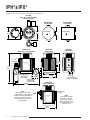
Figure 2. IPX 2 Current-to-Pressure Transmitter Housing Dimensions
TOP VIEW
(WITH –FR1 & –GA1 OPTIONS
AND PIPE CLAMP)
BOTTOM VIEW
(–NG OPTION)
BOTTOM VIEW
(NO OPTIONS)
125mm
(4.9 in)
89mm
(3.5 in)
FRONT VIEW
(WITH –FR1 & –GA1 OPTIONS)
MANUAL OVERRIDE &
FILTER HOLDER
MANUAL OVERRIDE &
FILTER HOLDER
SIDE VIEW
(–NG OPTION)
BACK VIEW
(NO OPTIONS)
–FR1
OPTION
154mm
(6.1 in)
INSTRUMENT
TAG
1/2 NPT
239mm
(9.4 in)
OUTPUT
VENT
1/4 NPT FEMALE
–GA1
PNEUMATIC
OPTION
INPUT PORT
1/4 NPT FEMALE
PNEUMATIC
OUTPUT PORT
200mm
(7.9 in)
NOTE:
BOTH SIDE FITTINGS ARE
PERMANENTLY ATTACHED.
DO NOT ATTEMPT TO REMOVE.
(THEY MAY BE INSTALLED ON
EITHER SIDE OF THE UNIT BY
THE FACTORY)
102mm
(4.0 in)
FRONT VIEW
(WITH –NG OPTION)
PERMANENT
FITTING
INSTRUMENT
TAG
166mm
(6.5 in)
6
The Interface Solution Experts
25mm
(1.0 in)
NATURAL GAS
VENT (–NG OPTION)
125mm
(4.9 in)
NOTE:
–NG1 MODEL SHOWN.
FOR THE –NG2, THE
ELECTRICAL CONDUIT
IS ON THE RIGHT SIDE,
AND PERMANENT PLUG
IS ON THE LEFT.
IPH 2 & IPX 2
Figure 3. IPH 2 Current-to-Pressure Transmitter Housing Dimensions
CONDUIT WIRE ENTRY
METRIC (M20 x 1.5)
OR NPT (1/2-14)
THREADS
140mm
(5.5 in)
76mm
(3.0 in)
OUT
163mm
(6.4 in)
IN
1/4 NPT
PNEUMATIC
INPUT PORT
FOR OPTIONAL
–FR1 FILTER/
REGULATOR/
GAUGE
33mm
(1.3 in)
1/4 NPT FEMALE
PNEUMATIC OUTPUT
PORT (COVERED BY
OPTIONAL –GA
OUTPUT GAUGE)
1/4 NPT
FEMALE
PNEUMATIC
OUTPUT
PORT
1/4 NPT FEMALE
PNEUMATIC INPUT
PORT (UNUSED PORT
IS PLUGGED)
136mm
(5.4 in)
WITH –FR1 OPTION
99mm
(3.9 in)
INSTRUMENT
TAG
84mm
(3.3 in)
25mm
(1.0 in)
51mm
(2.0 in)
72mm
(2.9 in DIA.)
MANUAL OVERRIDE
& FILTER HOLDER
17mm
(0.7 in)
69mm
(2.7 in)
89mm
(3.5 in)
The Interface Solution Experts
7
IPH 2 & IPX 2
Installation
The installation of the IPH2 or IPX2 is carried out in
three phases: the physical mounting of the unit, the
electrical connections phase, and the pneumatic
connections phase. It is strongly suggested that each
unit be calibrated according to the instructions in this
manual before being placed into service.
Phase One: Mounting
Figures 2 and 3 give the dimensions of the IPX2 and
IPH2, respectively. The illustrations also give the
dimensions of the available option hardware, which is
recommended for most installations. After placing the
unit in the desired location and orientation, secure the
housing with the optional pipe mounting hardware or
other appropriate fasteners.
The IPH2 or IPX2 may be installed at any angle–either
surface-mounted or attached to pipe or round conduit.
However, if water entering the I/P unit is a consideration, the IPH2 should be mounted within 45° of vertical,
while the IPX2 should be mounted with at least one vent
on a low side. The IPX2 with natural gas (–NG1 or
–NG2) option does not have an open vent, so water is
not a consideration.
Phase Two: Electrical Connections
To complete the electrical connections, route the
wiring through the conduit port to the terminal block,
then use a slotted-tip screwdriver with a maximum
head width of 3mm (0.125-inch) to loosen the
terminal screws. (Not necessary for IPX2 –NG1 or
–NG2 installation.)
For all units except the IPX2 –NG1 or –NG2, connect
positive lead (+) to the +PS terminal, and negative lead
(–) to the –PS terminal. Tighten the terminal screws
until snug.
Caution:
When connecting the IPX 2 Natural Gas (–NG1 or –NG2)
model, use an appropriately certified conduit box and
wire connectors. Do not attempt to remove the seal
fitting, as it is necessary for natural gas certification.
Connect the positive lead (+) to the red wire from the
seal fitting, and the negative lead (–) to the black wire
from the seal fitting.
Use shielded, twisted-pair wiring for low-level input.
Ground the shielding wire as close as possible to the
installed unit.
8
The Interface Solution Experts
Recommended Ground Wiring Practices
Moore Industries recommends the following ground
wiring practices:
• Any Moore Industries product in a metal
case or housing should be grounded.
• The protective earth conductor must be
connected to a system safety earth ground
before making any other connections.
• All input signals to, and output signals
from, Moore Industries’ products should be
wired using a shielded, twisted pair
technique. Shields are to be connected to an
earth or safety ground at the unit itself.
• The maximum length of unshielded input
and output signal wiring should be 2-inches.
Power Sourcing Parameters for General
Locations, Intrinsically Safe, and
Non-Incendive/Type N applications
In accordance with IEC 1010.1 Annexes F.2.1 and H
(all models) or any equivalent international standard,
the input terminals must be connected to and/or
supplied from a certified energy limiting Class 2 or a
Separated Extra Low Voltage (S.E.L.V.) power supply
separated from all mains by double/reinforced
insulation.
CE Conformity
Installation of any Moore Industries’ products that
carry the CE certification (Commission
Electrotechnique) must adhere to the guidelines in
this manual in order to meet the requirements set
forth in applicable EMC (Electromagnetic
Compatibility) directives (EN55011, EN 50082-1,
EN50082-2, etc.) Consult the factory for the most
current information on products that have been CE
certified.
IPH 2 & IPX 2
Phase Three:
Pneumatic Connections
To complete the final phase of installation, connect the
supply line to the ¼-inch NPT female port labeled “IN”.
Connect the output line to the ¼-inch NPT female port
labeled “OUT”. All tubing must have at least 6mm
(¼-inch) inside diameter or the maximum flow will be
limited.
Note:
Seal all fittings with Teflon® tape, or equivalent.
Always “blow down” (purge) all tubing and the
controlled device before connecting the IPH2 or IPX2.
Manual Override Screw
If you are in a potentially explosive environment and do
not want to apply electric power to the unit with the
cover removed, the pneumatic installation may be
tested by loosening the manual override screw on the
bottom of the unit. The output pressure will go to the
supply pressure. Be sure to tighten the manual override
screw after test.
WARNING:
IPX 2 units installed in a natural gas application must
have the natural gas vent properly connected. Follow
the directions below to install an IPX 2 with –NG1 or
–NG2 options into a natural gas application.
Natural Gas Applications
Customers using the IPX2 with –NG1 or –NG2 options
to regulate a sweet natural gas application (H2S levels
are not to exceed 20ppm) must also make the vent port
connections. Connect the Natural Gas Vent (shown in
Figure 2) to a device prepared to receive natural gas.
After connection, the fittings, cover, and filter/test
screw should be tested for leaks.
For an outdoor system, ventilation should consist of a
weather-proofed connection between the transmitter
exhaust and a riser, six feet above the transmitter and
control valve assembly. The riser should be shepherdcrooked to prevent rain or incident water from accumulating at the base. In accordance with local safety
regulation, an in-line flame arrestor should be applied to
the riser to prevent flash back to the transmitter from an
external, spontaneous flame source.
For an indoor system, ventilation must consist of a
leak-proof connection from the exhaust of the transmitter to a process vent. The process vent should already
be dedicated for natural gas excursions and should
conform to all standards for flaring or after-burn, and
flame arrest, as dictated by local environmental and
safety regulations.
Indoor natural gas operations are typically monitored to
maintain safety conformance outside the lower and
upper explosion limits (LEL and UEL). To add a natural
gas operated transmitter in these cases, consideration
should be made as to the extent of natural gas leak
detection legacy to the installed transmitter. Placement
of the transmitter should be such that detection and
alarming surround any critical connections between the
transmitter and the natural gas process.
If the natural gas driven transmitter is to be installed
indoors with no legacy monitoring capabilities,
additional consideration must be made to ensure the
operating area is well-ventilated and the transmitter can
be exhausted to process vent. Furthermore, monitoring
with remote annunciation within LEL and UEL should be
projected as an upgrade to the facility, concurrently with
this installation. The transmitter installation must
adhere to local environmental and safety regulations.
WARNING:
IPX 2 units installed in a natural gas application must
have the natural gas vent properly connected. Failure
to do so may result in an explosion. The –FR1 option
should not be used with a flammable gas because it
has a vent to atmosphere. A filter-regulator without a
vent may be used. For natural gas certification to be
valid, the vent system must be able to maintain <1psig.
Filters. The IPH2 and IPX2 requires filtered, dry,
regulated, instrument-quality air to prevent clogging and
to ensure extended periods of maintenance-free
operation. Moore Industries suggests the following
levels of filtering protection:
•
Pre-filter – A general purpose “rough” filter, used to
reduce particulate matter to 5 microns in size. Also
removes bulk liquids. Although not required, this
filter is especially recommended to protect the 0.01
micron final filter when used.
•
Final Filter – A second, final filter is recommended
to remove particulate matter in sizes down to 0.01
micron. This filter removes virtually all condensable liquids from the air stream as well.
•
Filter/Regulator Module Option – A combined
filter/regulator assembly, the -FR1 Option, offered
as an accessory for either the IPH2 or IPX2,
removes particles down to 0.01 microns, supplying
regulated, instrument-quality air to the unit. This
space-saving module is affixed to the supply port,
and comes with a pressure gauge scaled in both
psi (0-60) and Bars (0-4).
The Interface Solution Experts
9
IPH 2 & IPX 2
Operation
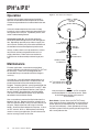
Figure 4. Filter Replacement Diagram
Once the unit has been configured and installed, it
operates unattended with the exception of the minor
maintenance procedures that are described in the next
section.
2
IPH OR IPX
BOTTOM
2
If the unit is determined to be the cause of a loop
irregularity, carry out the maintenance procedure in the
next section of this manual. If problems persist, refer
to the Troubleshooting Section.
Instrument-quality Air. Air from the application
continuously flows through the IPH2/IPX2 during operation. Depending upon the purity of the air supply, the
unit’s internal assembly may have to be removed and
cleaned to ensure continued optimum performance.
Initially, random checks can help establish a satisfactory internal maintenance geared to the user’s air
supply cleanliness. Refer to the next section for
instruction on the disassembly and cleaning of your
unit.
O-RING
P/N 802-187-24
ORIFICE
ASSEMBLY
FILTER
P/N 800-829-43
O-RING
P/N 802-186-24
SPRING (IF LOST)
P/N 800-011-24
Maintenance
For most applications, no maintenance outside of
routine inspection and calibration of the IPH2 or IPX2 will
be necessary. These units are designed to work
unattended for up to six months with little change in
accuracy.
Occasionally, a unit will become clogged when its air
source becomes contaminated. An internal filter will
prevent the control orifice and nozzle from being
clogged. To replace the filter, you will need to order the
filter and two (for IPX2) or three (for IPH2 and IPX2 –NG1
or –NG2) o-rings from Moore Industries, (see Figure 4
for part numbers) then follow the instructions below.
This filter is not intended to replace any of the filters
described in the Installation section.
Use a screwdriver to remove the filter holder from the
bottom of the unit. Remove the orifice assembly and
filter from the filter holder, taking care not to lose any of
the parts. Replace the filter and o-rings in the filter
holder. Screw the filter holder back into place. If this is
an IPX2 unit with –NG1 or –NG2 options and is being
used in a natural gas application, you will also want to
test for natural gas leaks at this time.
10
The Interface Solution Experts
FILTER
HOLDER
O-RING
(IPX2 –NG) P/N 802-198-24
(IPH2) P/N 802-191-24
Note:
After maintenance, each IPH 2 or IPX 2 should be
recalibrated before it is returned to service. Refer
to the Calibration Section of this manual
for instructions.
Drain Check. System filters (not IPX2/IPH2 filters)
have automatic drains that depend on the fluctuation of
system pressure to induce drainage. A stable system
may not drain efficiently. Check periodically for clogs
and drain system’s filters by pushing the drainage valve
with a small probe or wire.
IPH 2 & IPX 2
Troubleshooting
the IPH2 & IPX2
Many components of the IPH2 and IPX2 have been
thermally aged, tested, and selected. This usually
makes field repair unnecessary.
It is recommended that any properly maintained unit
found to be performing below specifications be returned
to the factory in accordance with the instructions found
on the back cover of this manual.
Customer Service
If service assistance is ever required for your IPH2 or
IPX2, refer to the back cover of this manual for the
telephone numbers to Moore Industries’ STAR Center
customer service department.
If possible, make a note of the model number of the
offending module before calling. For the fastest
assistance, try to gather information on the unit(s)
serial number and the job and purchase order number
under which it was shipped.
If a problem is suspected with the IPH2 or IPX2, review
the following steps:
1. Verify that bench instruments used to take
measurements have the proper range and accuracy
and are within current certification period limits.
2. If a change in the relationship between the input
and output is detected, attempt a re-calibration of
the unit.
3. If the response time lengthens, or if the span drops,
check the system for a blockage due to air supply
contamination.
The complete valve assembly can be removed from the
housing for replacement without disturbing the connections to the housing. Contact customer service for
details.
The Interface Solution Experts
11
Declaration of Conformity
EMC Directive 89/336/EEC
• Manufacturer’s Name:
• Manufacturer’s Address:
Moore Industries-International, Inc.
16650 Schoenborn Street
North Hills, CA 91343-6196
USA
Declares that the product(s):
• Product Name:
IPH2
MODEL /
• Model Number(s):
IPH2
INPUT
/
OUTPUT
*
*
/
POWER
*
/
OPTIONS
/
*
HOUSING
*
* Indicates any input, output, power, option and housing as listed on the product data sheet
• Conforms to the following EMC specifications:
EN 61326-1, 1998, Electromagnetic Compliance (EMC) requirements for electrical equipment for control use
• Supplementary Information:
None
2 October 2002
Date
Fred Adt
Quality Assurance Director
Robert Stockham
Moore Industries-Europe General Mgr.
European Contact: Your Local Moore Industries Sales and Service Office
United States • info@miinet.com
Tel: (818) 894-7111 • FAX: (818) 891-2816
Australia • sales@mooreind.com.au
Tel: (02) 8536-7200 • FAX: (02) 9525-7296
Belgium • info@mooreind.be
Tel: 03/448.10.18 • FAX: 03/440.17.97
The Netherlands • sales@mooreind.nl
Tel: (0)344-617971 • FAX: (0)344-615920
China • sales@mooreind.sh.cn
Tel: 86-21-62491499 • FAX: 86-21-62490635
United Kingdom • sales@mooreind.com
Tel: 01293 514488 • FAX: 01293 536852
Declaration of Conformity
EMC Directive 89/336/EEC
• Manufacturer’s Name:
• Manufacturer’s Address:
Moore Industries-International, Inc.
16650 Schoenborn Street
North Hills, CA 91343-6196
USA
Declares that the product(s):
• Product Name:
IPX2
MODEL /
• Model Number(s):
IPX2
INPUT
/
OUTPUT
*
*
/
POWER
*
/
OPTIONS
/
*
HOUSING
*
* Indicates any input, output, power, option and housing as listed on the product data sheet
• Conforms to the following EMC specifications:
EN 61326-1, 1998, Electromagnetic Compliance (EMC) requirements for electrical equipment for control use
• Supplementary Information:
None
2 October 2002
Date
Fred Adt
Quality Assurance Director
Robert Stockham
Moore Industries-Europe General Mgr.
European Contact: Your Local Moore Industries Sales and Service Office
United States • info@miinet.com
Tel: (818) 894-7111 • FAX: (818) 891-2816
Australia • sales@mooreind.com.au
Tel: (02) 8536-7200 • FAX: (02) 9525-7296
Belgium • info@mooreind.be
Tel: 03/448.10.18 • FAX: 03/440.17.97
The Netherlands • sales@mooreind.nl
Tel: (0)344-617971 • FAX: (0)344-615920
China • sales@mooreind.sh.cn
Tel: 86-21-62491499 • FAX: 86-21-62490635
United Kingdom • sales@mooreind.com
Tel: 01293 514488 • FAX: 01293 536852
CHECKED
Ground/Earth Path
Resistance Must
Not Exceed 1 Ω
Barrier or other
Associated
Apparatus
(2)
08/02
08/02
BY
G.E. 08/02
DATE
CB
APPROVAL
A
REVISION
PN
EU
NT
OU
VE
T
OU
PN
EU
OU
T
ISOMETRIC VIEW
(Cover not shown for clarity)
VE
NT
II 2GD EEx d IIC T5/T6
The IPX2 enclosure is certified to be
Explosion/Flame-Proof & Dust Ignition-Proof:
Class (I,II,III), Division 1, Groups A-G;
T
IN
Vmax or Ui = 30 VDC
Imax or Ii = 110 mA
Pmax or Pi = 0.6953 W
Ci = 0 µF
Li = 5 mH
Ca or Co ≥ Ci + Ccable
La or Lo ≥ Li + Lcable
Vmax or Ui ≥ Voc or Vt
Imax or Ii ≥ Isc or It
(Power/Loop, +PS/-PS):
Entity Parameters
-NG Option: Pressure at
the "Vent Out" must
always be less than 1 PSI.
EC
EL
-NG OPTION:
WIRE ASSEMBLY,
HERMETICALLY
SEALED FITTING*
-NG OPTION:
'DO NOT REMOVE'
WARNING TAG
*NOTE: THE -NG SEAL FITTING MAY BE
INSTALLED IN EITHER IPX2 CONDUIT PORT,
WITH PIPE PLUG INSTALLED IN OPPOSITE.
NOTICE RE PROPRIETARY INFORMATION: This drawing and the information contained herein are the proprietary property of Moore IndustriesInternational, Inc. (MII) and should not be reproduced or disclosed to any
third party without the written consent of an authorized officer of MII.
INITIAL RELEASE
REVISED BY
100-100-65
The IPX2 is designed to function at an
operating ambient temperature range of:
-40°C ≤ Tamb. ≤ +85°C
Must use +85°C suitable cabling.
IN
IN
EU
EU
PN
PN
-NG Option (Natural Gas)
BASE PLATE
Hazardous 'Classified' Locations/Areas
FMRC (US-NEC 500/505) & CSA (C22.2/1010.1):
Intrinsically Safe: Class I,II,III; Div. 1; Groups A-G
Class I, Zone 0, AEx ia IIC T6@60°C / T5@85°C
Non-Incendive: Class I, Div. 2, Groups A-D
Class II, Div. 2, Groups F & G and Class III, Div. 2
LCIE - CENELEC/ATEX 94/9/EC Directive:
I.S.:
II 1G EEx ia IIC T6@60°C / T5@85°C
Environmental Protection:
IPX2 (Standard / Air) - IP56 & NEMA Type 4X
IPX2 (-NG Option) - IP66 & NEMA Type 4X
TOP VIEW
(Cover not shown for clarity)
(3)
+PS
-PS
GROUND
-PS
+PS
IPX2
(WITH STANDARD
'Air' BASE PLATE)
1/2"NPT PIPE
PLUG* FOR
CONDUIT PORT
Intrinsically Safe System
For Hazardous 'Classified' Locations.
IPX2:
Current-to-Pressure Transmitter
NONE
Field Installation Diagram:
IPX2, Current-to-Pressure Transmitter
TITLE
DRAWING NUMBER
(1) Apparatus which is unspecified except that it must not be supplied from, or contain under normal or abnormal conditions a source of potential with respect to earth in excess of 250 VRMS or 250 VDC
which is considered to be the Safe Area's maximum voltage. Use a certified Class 2 or a Separated Extra Low Voltage (S.E.L.V.) power source.
(2) The Barrier or other Associated Apparatus must be approved by the "specific" (CSA/EECS/FM/LCIE/SAA/SIRA/TUV, etc..) certifying agency for I.S. connections in: "Class I-III, Division 1, Groups
A-G" locations. The output voltage (Voc, Vt or Vo) must not exceed 30 VDC & the output current (Isc, It or Io) must not exceed 110 mA. Also, it must be installed per the manufacturer's guidelines.
A Shunt Zener Barrier is NOT required for Class I, Division 2 (Non-Incendive/Type N) installations. Power source must be a limited circuit as stated in IEC 61010.1 Annex F.2.1 or equivalent standard.
(3) The combined Capacitance and Inductance of the inter-connecting cables and the PC Prog. Transmitters must not exceed the values indicated on the Associated Apparatus.
4- For FM applications, installation must be in accordance to 'ANSI-P12.6' (Installation of I.S. Systems for Hazardous 'Classified' Locations) and the National Electric Code 'ANSI/NFPA 70'. Also, a
dust-tight conduit seal must be used when installed in Class II and Class III environments. For CSA applications, adhere to the 'Canadian Electric Code C22.1' most current publication on I.S. installation
guidelines. For CENELEC/ATEX applications, adhere to 'BS5345 or EN 60079-14:1997' or any equivalent, most current and pertaining publication on I.S. installation guidelines.
5- Warning: Close cover tightly. Substitution of components may impair the Intrinsic Safety & Non-Incendivity of the unit. DO NOT open the unit when either energized or if an explosive gas/dust atmoshpere
may be present. Disconnect power before servicing. Also read, understand and adhere to the manufacturer's installation and operating procedures stated in the OEM User's Manual.
Notes:
(1)
Unspecified
Apparatus
Non-Hazardous / Safe Area
CERTIFIED PRODUCT
This is a controlled 'Related' or 'Schedule'
drawing. No modifications are permitted
without the notification and final approval
of the Certification Engineer (related dwgs.)
or the Certifying Agency (schedule dwgs.).
W. Ho
J.A.D.
Gus H. Elias 08/02
DECIMALS = ±inch/mm
= ±.1 /2.54
.X
= ±.03 /0.76 ENGINEER
.XX
= ±.010/0.25
.XXX
HOLES:=+.003-.002/+.08-.05 SCALE
ANGLES: = ± 30'
(UNLESS NOTED)
TOLERANCES
CONTROL DRAWING
CATEGORY
ZERO
SPAN
The Interface Solution Experts
CURRENT TO PRESSURE
TRANSMITTER
14
DRAWN
DO NOT SCALE DRAWING
IPH 2 & IPX 2
IPH 2 & IPX 2
The Interface Solution Experts
Moore Industries-International, Inc.
16650 Schoenborn Street
North Hills, CA 91343-6196
Telephone (818) 894-7111
FAX (818) 891-2816
E-mail: info@miinet.com
www.miinet.com
Product/Technical Descriptive Notice
IPX2: Field-Mount I/P (Current-to-Pressure) Converter
A loop-powered (2-wire) instrument that accepts a 4-20mA current signal input from a DCS, PLC or
PC-based control system, and converts it to a proportional pneumatic output (3-15psig, 0.2-1Bar,
20-100Kpa, etc.) to provide precise, proportional control of valves, actuators, and other pneumatically2
controlled devices. The IPX is designed and intended for use in industrial process control, factory
2
automation, and facility environmental control applications. The IPX usage and operating environment
covers both Non-Hazardous (General-Ordinary/Safe Areas) and Hazardous ‘Classified’ Locations.
2
Special design, construction, and materials specifications allow the model IPX with the -NG1 or -NG2
option to be used with “natural gas” as its pneumatic supply (commonly referred to as “sweet gas”,
2
consisting of up to 20ppm of Hydrogen Sulfide - H2S). This advantage allows the IPX to be installed in
remote compressor sites where it is too expensive or impossible to run a clean air supply. The
2
standard IPX unit utilizes “air” as its pneumatic control medium.
Detailed electrical guidelines, power ratings, mechanical features, terminal identification, wiring diagrams,
model configurations, and technical instructions for commissioning, installing and operating the
instrument are provided in the OEM User’s Manual, Product Literature (Data Sheet), Identification
Label/Tag, and the Intrinsically Safe System & Field Installation Diagram that are shipped with each unit.
Power must be sourced from a Class 2 power supply or Separated Extra Low Voltage (S.E.L.V.) Limited
Circuits as defined by CSA standard 1010.1 - Annexes H & F.2.1 or any equivalent international standard.
2
The IPX is in the process of acquiring numerous safety approvals in accordance with internationally
2
adopted standards such as the CEC, IEC and NEC. For North America, the standard (air) IPX will
qualify for CSA and FM certifications as an Explosion-Proof (Class I, II, III; Division 1; Groups A-G),
Intrinsically Safe and Non-Incendive (Class I, Divisions 1 & 2, Groups A-D) apparatus. Within an ambient
o
o
2
o
o
temperature range of -40 C to +85 C, the IPX will hold a T5@85 C/T6@60 C temperature classification
code. For Europe, it will be certified by LCIE (France) as a Flame-Proof (II 2GD EEx d IIC T5/T6),
Intrinsically Safe (II 1G EEx ia IIC T5/T6), and Type N (II 3G EEx nA II T5/T6) apparatus; to be clearly
2
marked in accordance with the CENELEC/ATEX 94/9/EC Directive. The IPX -NG will carry the same
2
certifications as the standard IPX2 (air), excluding the Non-Incendive/Type N classifications. The IPX
assembly consists of a pneumatic current-to-pressure transducer mounted in the IP56 (air) / IP66 (-NG)
rated enclosures in accordance with the environmental protection requirements of Clauses 7.3.2 and 8.1
of EN 50014:1997 plus Amendments 1 & 2, and 6.1 of EN 50020:1994. As per CSA’s Standard 1010.1
(or any equivalent international standard), the environmental conditions are set as: Pollution Degree = 2,
Installation Category = I, Altitude = 0 - 4000m (0 - 13,123ft), Humidity = 0 - 100% (non-condensing).
Manufacturer’s Declaration:
It is hereby declared that the above information pertaining to the IPX2 – produced by Moore
Industries-Int’l., is concisely stated as a description of its design purpose and usage intent.
Gus H. Elias - Senior Certification Engineer
20-Jul-2002
Document Control No.: 700-768-00A
The Interface Solution Experts
15
RETURN PROCEDURES
To return equipment to Moore Industries for repair, follow these four steps:
1. Call Moore Industries and request a Returned Material Authorization (RMA) number.
Warranty Repair –
If you are unsure if your unit is still under warranty, we can use the unit’s serial number
to verify the warranty status for you over the phone. Be sure to include the RMA
number on all documentation.
Non-Warranty Repair –
If your unit is out of warranty, be prepared to give us a Purchase Order number when
you call. In most cases, we will be able to quote you the repair costs at that time.
The repair price you are quoted will be a “Not To Exceed” price, which means that the
actual repair costs may be less than the quote. Be sure to include the RMA number on
all documentation.
2. Provide us with the following documentation:
a) A note listing the symptoms that indicate the unit needs repair
b) Complete shipping information for return of the equipment after repair
c) The name and phone number of the person to contact if questions arise at the factory
3. Use sufficient packing material and carefully pack the equipment in a sturdy shipping
container.
4. Ship the equipment to the Moore Industries location nearest you.
The returned equipment will be inspected and tested at the factory. A Moore Industries
representative will contact the person designated on your documentation if more information is
needed. The repaired equipment, or its replacement, will be returned to you in accordance with
the shipping instructions furnished in your documentation.
WARRANTY DISCLAIMER
THE COMPANY MAKES NO EXPRESS, IMPLIED OR STATUTORY WARRANTIES (INCLUDING ANY WARRANTY OF MERCHANTABILITY OR OF FITNESS
FOR A PARTICULAR PURPOSE) WITH RESPECT TO ANY GOODS OR SERVICES SOLD BY THE COMPANY. THE COMPANY DISCLAIMS ALL WARRANTIES ARISING FROM ANY COURSE OF DEALING OR TRADE USAGE, AND
ANY BUYER OF GOODS OR SERVICES FROM THE COMPANY ACKNOWLEDGES THAT THERE ARE NO WARRANTIES IMPLIED BY CUSTOM OR
USAGE IN THE TRADE OF THE BUYER AND OF THE COMPANY, AND THAT
ANY PRIOR DEALINGS OF THE BUYER WITH THE COMPANY DO NOT IMPLY THAT THE COMPANY WARRANTS THE GOODS OR SERVICES IN ANY
WAY.
ANY BUYER OF GOODS OR SERVICES FROM THE COMPANY AGREES
WITH THE COMPANY THAT THE SOLE AND EXCLUSIVE REMEDIES FOR
BREACH OF ANY WARRANTY CONCERNING THE GOODS OR SERVICES
SHALL BE FOR THE COMPANY, AT ITS OPTION, TO REPAIR OR REPLACE
THE GOODS OR SERVICES OR REFUND THE PURCHASE PRICE. THE
COMPANY SHALL IN NO EVENT BE LIABLE FOR ANY CONSEQUENTIAL OR
INCIDENTAL DAMAGES EVEN IF THE COMPANY FAILS IN ANY ATTEMPT
TO REMEDY DEFECTS IN THE GOODS OR SERVICES , BUT IN SUCH CASE
THE BUYER SHALL BE ENTITLED TO NO MORE THAN A REFUND OF ALL
MONIES PAID TO THE COMPANY BY THE BUYER FOR PURCHASE OF THE
GOODS OR SERVICES.
ANY CAUSE OF ACTION FOR BREACH OF ANY WARRANTY BY THE
COMPANY SHALL BE BARRED UNLESS THE COMPANY RECEIVES
FROM THE BUYER A WRITTEN NOTICE OF THE ALLEGED DEFECT OR
BREACH WITHIN TEN DAYS FROM THE EARLIEST DATE ON WHICH THE
BUYER COULD REASONABLY HAVE DISCOVERED THE ALLEGED DEFECT OR BREACH, AND NO ACTION FOR THE BREACH OF ANY WARRANTY SHALL BE COMMENCED BY THE BUYER ANY LATER THAN
TWELVE MONTHS FROM THE EARLIEST DATE ON WHICH THE BUYER
COULD REASONABLY HAVE DISCOVERED THE ALLEGED DEFECT OR
BREACH.
RETURN POLICY
For a period of thirty-six (36) months from the date of shipment, and under
normal conditions of use and service, Moore Industries ("The Company") will
at its option replace, repair or refund the purchase price for any of its manufactured products found, upon return to the Company (transportation charges
prepaid and otherwise in accordance with the return procedures established
by The Company), to be defective in material or workmanship. This policy
extends to the original Buyer only and not to Buyer's customers or the users
of Buyer's products, unless Buyer is an engineering contractor in which case
the policy shall extend to Buyer's immediate customer only. This policy shall
not apply if the product has been subject to alteration, misuse, accident, neglect or improper application, installation, or operation. THE COMPANY
SHALL IN NO EVENT BE LIABLE FOR ANY INCIDENTAL OR CONSEQUENTIAL DAMAGES.
United States • info@miinet.com
Tel: (818) 894-7111 • FAX: (818) 891-2816
Australia • sales@mooreind.com.au
Tel: (02) 8536-7200 • FAX: (02) 9525-7296
© 2005 Moore Industries-International, Inc.
Belgium • info@mooreind.be
Tel: 03/448.10.18 • FAX: 03/440.17.97
The Netherlands • sales@mooreind.nl
Tel: (0)344-617971 • FAX: (0)344-615920
China • sales@mooreind.sh.cn
Tel: 86-21-62491499 • FAX: 86-21-62490635
United Kingdom • sales@mooreind.com
Tel: 01293 514488 • FAX: 01293 536852
Specifications and Information subject to change without notice.
User’s Manual Supplement
IPT2 and IPH2 & IPX2
Current-to-Pressure Transmitters
Reverse Output Range
April 2004
A typical complete model number would appear as:
The following information accompanies data in the
IPT2 Current-to-Pressure Transmitter User’s Manual,
170-730-00, Revision A and the IPH2 & IPX2 Current-toPressure Transmitters User’s Manual, 170-755-00,
Revision A .
IPT2/4-20MA/15-3PSIG/20PSI/-FA1 [DIN]
This document concerns those of our customers that use
our latest high-performance Current-to-Pressure Transmitters and have specified a reverse output range.
This supplement is for units with a base model designation of IPT2, IPH2 and IPX2. Typical reverse output
ranges are as follows:
20 - 0PSIG
17 - 1PSIG
15 - 3PSIG
16.6 - 3PSIG
18 - 3PSIG
27 - 3PSIG
30 - 6PSIG
1 - .2KBAR
100 - 20KPA
1 - .2KGCM2
.10 - .02MPA
United States • info@miinet.com
Tel: (818) 894-7111 • FAX: (818) 891-2816
Australia • sales@mooreind.com.au
Tel: (02) 8536-7200 • FAX: (02) 9525-7296
© 2005 Moore Industries-International, Inc.
170-730-02A
The high-performance line of I/P transmitters utilizes an
internal feedback loop to ensure accurate operation. The
feedback loop consists of an internal pressure transducer
that samples the unit’s output pressure and compares it
to the input signal. This allows the unit’s output to track
the input signal. Other I/P transmitters, such as our
original IPT, IPH and IPX models, rely solely on mechanical positioning. This is what makes the IPT2, IPH2
and IPX2 highly desirable.
Since the feedback loop requires power to operate, when
there is no input power to the unit, the pneumatic output
will be shut off. Units that use mechanical positioning
only, will typically still have a pneumatic output when
power is removed. By example, a unit (IPT, IPH and
IPX) with an output range of 15 - 3PSIG will output
approximately 18PSIG when the input signal is removed.
This is not an issue except for those users that rely on
this elevated output (18PSIG) to maintain a valve’s
position upon the unexpected loss of input signal (420mA). In such cases, the IPT2, IPH2 and IPX2 units
react differently by shutting off the pneumatic output.
Belgium • info@mooreind.be
Tel: 03/448.10.18 • FAX: 03/440.17.97
The Netherlands • sales@mooreind.nl
Tel: (0)344-617971 • FAX: (0)344-615920
China • sales@mooreind.sh.cn
Tel: 86-21-62491499 • FAX: 86-21-62490635
United Kingdom • sales@mooreind.com
Tel: 01293 514488 • FAX: 01293 536852
Specifications and information subject to change without notice.
User’s Manual Supplement
IPX2 Current-to-Pressure Transmitter
With -RO Option
February 2007
The following information accompanies the IPH2 & IPX2
Current-to-Pressure Transmitters User’s Manual (Part
Number: 170-755-00, Revision A) to include the model
IPX2-RO (IPX2 with -RO option). The IPX2-RO is a
User-Selectable Direct/Reverse Output version of Moore
Industries’ IPX2.
The IPX2-RO, which ranges from 3-27PSIG (Direct
mode)/27-3PSIG (Reverse mode), includes two sets of
Zero and Span potentiometers (Direct and Reverse) along
with a Direct/Reverse Selector Switch.
Figure S-1. IPX2-RO Front Panel Configuration
+PS -PS
DIRECT
DIRECT
ZERO
If the switch is placed in the Direct position, the instrument will behave as the standard IPX2 in that the Zero
potentiometer will adjust the 3PSIG end while Span
adjusts the 27PSIG limit. The direct output will range
from 3-27PSIG.
REVERSE
IPX
SPAN
REVERSE
2 CURRENT TO PRESSURE
TRANSMITTER
MOORE INDUSTRIES
Setting the switch to the Reverse position places the
instrument in reverse output mode. The Zero potentiometer will adjust the 3PSIG end while Span adjusts the
27PSIG limit. The reverse output will range from
27-3PSIG.
With the exception of the information outlined above, the
IPX2-RO behaves and operates just as the IPX2 and
adheres to the specifications and instructions described
in the IPH2 & IPX2 Current-to-Pressure Transmitters
User’s Manual.
United States • info@miinet.com
Tel: (818) 894-7111 • FAX: (818) 891-2816
Australia • sales@mooreind.com.au
Tel: (02) 8536-7200 • FAX: (02) 9525-7296
© 2007 Moore Industries-International, Inc.
170-755-05A
Belgium • info@mooreind.be
Tel: 03/448.10.18 • FAX: 03/440.17.97
The Netherlands • sales@mooreind.nl
Tel: (0)344-617971 • FAX: (0)344-615920
China • sales@mooreind.sh.cn
Tel: 86-21-62491499 • FAX: 86-21-62490635
United Kingdom • sales@mooreind.com
Tel: 01293 514488 • FAX: 01293 536852
Specifications and information subject to change without notice.