1
Freescale Semiconductor
Device Errata
MCF5307 Device Errata
This document identifies implementation differences
between particular versions of the MCF5307 processor
and the description of the MCF5307 processor contained
in the MCF5307 User’s Manual. Please check the WWW
at http://www.motorola.com/ColdFire for the latest
updates. This errata lists any processor differences from
the following documents:
• MCF5307 User’s Manual
• MCF5307 User’s Manual Mask Set Addendum
• ColdFire Microprocessor Family Programmer’s
Reference Manual
This document applies to the following mask sets:
0H55J, 1H55J, 1J20C, and 2J20C. Designers can
differentiate whether they have a xH55J mask set or
xJ20C mask set by reading the IDCODE register in the
JTAG module of the MCF5307.
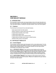
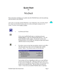
The IDCODE register shown in Table 1 will be identical
between mask sets except for the version number. For an
xH55J mask, idcode[31:28]=version no.= 0000, while
for an xJ20C mask, idcode[31:28]=version no.=0001.
All other bits remain the same.
This document contains information on a new product. Specifications and information herein
are subject to change without notice.
© Freescale Semiconductor, Inc., 2004. All rights reserved.
MCF5307ER
Rev. 4.2, 08/2004
Table 1. MCF5307 IDCODE Register
31
30
29
28
27
26
25
24
23
22
21
20
19
18
17
16
x
x
x
x
0
1
0
0
1
1
0
0
0
0
0
0
Version No.
Design Center= ColdFire
Device No.
15
14
13
12
11
10
9
8
7
6
5
4
3
2
1
0
0
0
1
1
0
0
0
0
0
0
0
1
1
1
0
1
Device No.
JEDEC No.
-
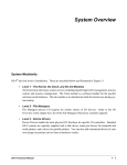
Table 2. Summary of MCF5307 Errata
Applicable Mask Set
Errata
ID
Module
Affected
Date Errata
Added
1
External
Bus
01/18/1999
Yes
Yes
TS Asserts Before Tri-stating During External
Master Arbitration
2
External
Bus
01/18/1999
Yes
Yes
TA Asserts for an Extra Clock During an External
Master Burst-line Write
3
External
Bus
01/18/1999
Yes
Yes
MBAR Reads Execute an External Bus Cycle
4
External
Bus
01/18/1999
Yes
Yes
Added Latency During External Master Access of
On-chip Peripherals
5
Core
01/18/1999
Yes
Yes
CPUSHL Instruction Fails to Push if CACR[31] = 0
6
Core
01/18/1999
Yes
Yes
Contents of Line-fill Buffer Lost During Warm Reset
7
Debug
01/18/1999
Yes
Yes
Misaligned WDDATA Operands Not Captured
8
Debug
01/18/1999
Yes
Yes
CCR Corrupted During Misaligned
Memory-to-Memory MOVE.L while Capturing
Operands for DDATA
9
Debug
01/18/1999
Yes
Yes
Unexpected Data Breakpoint Trigger
10
DRAMC
01/18/1999
Yes
Yes
RAS[1:0] Negation during Page-mode Access in
Asynchronous DRAM Mode
11
SIM
01/18/1999
Yes
Yes
SWT Servicing Sequence Fails
12
Elec. Specs 01/18/1999
Yes
Yes
13
Elec. Specs 01/18/1999
Yes
Yes
Errata Title
0H55J 1H55J 1J20C 2J20C
Yes
Yes
DC Parametric Modifications
See
See AC Timing Modifications for the xH55J Mask
Errata Errata
#26
#26
14
DMA
01/18/1999
Yes
Yes
Direct Memory Access Controller (DMA) Cycle Steal
Mode Misoperation
15
DRAMC
01/18/1999
Yes
Yes
SDRAM Edgeselect Mode
16
Cache
04/09/1999
Yes
Yes
Incorrect Behavior of Burst-write MOVEM after
Read Cache Miss
MCF5307 Device Errata, Rev. 4.2
2
Freescale Semiconductor
Table 2. Summary of MCF5307 Errata (continued)
Applicable Mask Set
Errata
ID
Module
Affected
Date Errata
Added
17
several
04/09/1999
Yes
Yes
Bogus Write-protect Faults for some MOVEM or
CPUSHL Instructions
18
Core
04/09/1999
Yes
Yes
Incorrect Branch Target Instruction Fetches
19
Core
04/09/1999
Yes
Yes
Problem Involving Undetected Level 7 Interrupt
20
Core
04/09/1999
Yes
Yes
21
Debug
04/09/1999
Yes
Yes
22
SIM
04/09/1999
Yes
Yes
Yes
Yes
Spurious Interrupt Generated when Masked IMR
Interrupt is Taken
23
DRAMC
04/09/1999
Yes
Yes
Yes
Yes
External Master Termination is Not Always Correct
when Using SDRAM Controller
24
DMA
04/09/1999
Yes
Yes
25
DMA
08/18/1999
Yes
Yes
26
Elec. Specs 09/17/1999
Errata Title
0H55J 1H55J 1J20C 2J20C
See
See
Errata Errata
#13
#13
Yes
Yes
Longword Aligned Fetch Containing Illegal Opcode
(Upper 16-bits) plus Bxx.b Opcode (lower 16-bits)
Generates Bogus Fetch Address
Correct Operation of Debug_RevB “syncPC”
Command is Sequence-dependent
Source Address Increment Bit for DMA Channels
does Not Increment Properly
Yes
When Using Multiple DMA Channels, a Write by a
DMA Channel Could Get Lost if a Higher Priority
DMA Channel Requests the Internal Bus
Simultaneously.
Yes
Yes
AC Timing Modifications for xJ20C Mask
Yes
Yes
MAC Fractional –1 * –1 Overflow Detection Erratic
27
MAC
05/24/2000
28
Debug
05/24/2000
Yes
Yes
Yes
Yes
Data Inversion Triggers are Incorrect for Word and
Longword Accesses
29
Debug
05/24/2000
Yes
Yes
Yes
Yes
Second-level Breakpoint Trigger Missed if it Occurs
on the Cycle Immediately after Assertion of
First-level Trigger
30
DMA
05/24/2000
Yes
Yes
Yes
Yes
DMA Writes to UART Cause Transmission Errors
31
DMA
05/24/2000
Yes
Yes
Yes
Yes
DMA Single-Address Access Mode and Cycle-steal
Mode do Not Work Together
32
DMA
arbiter
05/24/2000
Yes
Yes
Yes
Yes
DMA Channel Arbiter Hangs in Round-robin Mode
33
Debug
05/24/2000
Yes
Yes
Yes
Yes
Processor Status Reporting Anomaly during Debug
Exception Processing
34
Debug
05/24/2000
Yes
Yes
Yes
Yes
Forcing Emulator Mode from Reset by Asserting
CSR[13] does Not Work
35
SIM
01/22/04
Yes
Yes
Yes
Yes
Corrupted Return PC in Exception Stack Frame
36
Debug
08/02/04
Yes
Yes
Yes
Yes
Incorrect debug interrupts triggered
MCF5307 Device Errata, Rev. 4.2
Freescale Semiconductor
3
TS Asserts Before Tri-stating During External Master Arbitration
1
TS Asserts Before Tri-stating During External
Master Arbitration
1.1
Description
This errata applies only when using an external master and the EARBCTRL control bit of the Default Bus
master Register (MPARK) is cleared. If the EARBCTRL control bit is cleared, (allowing slave bus cycles
without arbitrating for the external bus) and bus grant (BG) negates at the initiation of a slave bus cycle,
TS may be asserted and may not be negated prior to the 5307 tri-stating and releasing the bus. This leaves
the TS signal asserted for the external master or control logic.
1.2
•
•
•
Workaround
No external master in the system.
If there is an external master other than the 5307, the EARBCTRL bit must be set, requiring
arbitration for the external bus prior to initiation of slave bus cycles.
Provide an external pull-up on the TS signal to negate TS after the 5307 releases the bus.
MASKS: 0H55J, 1H55J01/18/1999
2
TA Asserts for an Extra Clock During an External
Master Burst-line Write
2.1
Description
This errata applies only when using an external master with the MCF5307. If the external master is either
executing a line write burst to internal MCF5307 peripherals or if the external master is using the
MCF5307 control signals to execute a line write burst cycle, then during the last transfer of either of these
two scenarios, the transfer acknowledge (TA) signal may be erroneously asserted for two cycles.
2.2
•
•
Workaround
No external master in the system.
If there is an external master other than the 5307, do not allow the external master to do burst line
writes to slave bus modules.
MASKS: 0H55J, 1H55J01/18/1999
MCF5307 Device Errata, Rev. 4.2
4
Freescale Semiconductor
MBAR Reads Execute an External Bus Cycle
3
MBAR Reads Execute an External Bus Cycle
3.1
Description
A read of the MBAR register causes the execution of an external bus cycle which could result in an
external bus lock up while waiting for a TA termination signal.
3.2
•
Workaround
Do not allow reads from the MBAR address.
MASKS: 0H55J, 1H55J1/18/1999
4
Added Latency During External Master Access
of On-chip Peripherals
4.1
Description
This is only an issue when there is an external bus master accessing 5307 on-chip peripherals or when an
on-chip alternate master is used when the SHOWDATA and EARBCTRL bit in the MPARK register is set
to 1. For the external master scenario, this bug only affects performance, not functionality. On the initial
bus cycle of a transfer by an external master to/from a 5307 peripheral, an extra cycle of latency is present
in the response of the 5307 (TA and data[31:0]). When using the on-chip DMA, during an internal
peripheral fetch followed by a DMA cycle, this added TA latency can cause DMA cycle to be erroneously
terminated.
4.2
•
Workaround
The current timing should not cause any functional problems.
MASKS: 0H55J, 1H55J1/18/1999
5
CPUSHL Instruction Fails to Push if
CACR[31] = 0
5.1
Description
The CPUSHL instruction should force a cache line push at the specified cache address for modified data,
regardless of the state of the cache enable defined in CACR[31]. In the current implementation, the
CPUSHL operates correctly only if the cache is enabled, that is, CACR[31] = 1.
MCF5307 Device Errata, Rev. 4.2
Freescale Semiconductor
5
Contents of Line-fill Buffer Lost During Warm Reset
5.2
•
Workaround
Guarantee that CACR[31] = 1 whenever a CPUSHL instruction is executed.
MASKS: 0H55J, 1H55J1/18/1999
6
Contents of Line-fill Buffer Lost During Warm
Reset
6.1
Description
If a “warm reset” occurs while the Version 3 ColdFire processor core is operating, the documentation
indicates that the cache contents are to be unaffected. With this errata, the occurrence of any reset causes
the line fill buffer to be marked as invalid. Thus, if the line fill buffer contained valid data at the time of a
warm reset, the initial state of the buffer after reset is empty, causing loss of the previous contents.
6.2
•
Workaround
If the cache state is required to be consistent with across warm resets, it is necessary to flush the
cache contents before the occurrence of the warm reset.
MASKS: 0H55J, 1H55J1/18/1999
7
Misaligned WDDATA Operands Not Captured
7.1
Description
Operands referenced by WDDATA instructions must be aligned on either 0-modulo-2 addresses or
0-modulo-4 addresses. Any other misaligned operand reference will cause the operand not to be captured
by the WDDATA instruction.
7.2
•
Workaround
Guarantee that all operands referenced by WDDATA instructions are aligned, that is, 16-bit
references on 0-modulo-2 addresses and 32-bit references on 0-modulo-4 addresses.
MASKS: 0H55J, 1H55J1/18/1999
MCF5307 Device Errata, Rev. 4.2
6
Freescale Semiconductor
CCR Corrupted During Misaligned Memory-to-Memory MOVE.L while Capturing Operands for DDATA
8
CCR Corrupted During Misaligned
Memory-to-Memory MOVE.L while Capturing
Operands for DDATA
8.1
Description
During the execution of certain 32-bit memory-to-memory move instructions with a misaligned source
operand, there is a possibility that the Condition Code Register (CCR) may be incorrectly loaded if the
processor’s operand Execution pipeline is stalled for one or more cycles by the Debug Data module after
the source operand access is completed. This failure can only occur if the debug unit’s
Configuration/Status Register is set to capture operand reads and/or writes for display on the DDATA
output port.
8.2
Workaround
There are several potential workarounds to this problem:
• Do not enable operand capture and display on the DDATA outputs.
• If capturing operands for DDATA, guarantee that all memory-to-memory move instructions
reference aligned operands.
• If capturing operands for DDATA, proceed any misaligned memory-to-memory move with a
NOP instruction to provide pipeline synchronization.
MASKS: 0H55J, 1H55J1/18/1999
9
Unexpected Data Breakpoint Trigger
9.1
Description
If a data breakpoint monitoring multiple word and byte values is configured, there is a possibility that the
breakpoint may falsely trigger. As an example, if the breakpoint hardware is configured to monitor for a
certain byte value within a range of addresses, a byte reference is made and the data breakpoint value is
present on the data bus, but in a different byte lane, a false trigger could be generated. The logic to fully
qualify the reference size and the appropriate bytes of the data bus is incorrect.
Note: this bug does NOT affect the ability to configure a breakpoint of a certain data value at a certain
address. The false trigger can only occur when multiple bits in the following fields of the Trigger
Definition Register are asserted:
• if multiple bits of TDR[27:26] are set, and a level 2 trigger is enabled;
• if multiple bits of TDR[25:22] are set, and a level 2 trigger is enabled;
• if multiple bits of TDR[11:10] are set, and a level 1 trigger is enabled;
MCF5307 Device Errata, Rev. 4.2
Freescale Semiconductor
7
RAS[1:0] Negation during Page-mode Access in Asynchronous DRAM Mode
•
9.2
•
if multiple bits of TDR[9:6] are set, and a level 1 trigger is enabled, then a false trigger may
occur.
Workaround
Restrict the use of the data breakpoint to only a single operand, and enable only a single bit in the
TDR appropriate for the operand size and location on the data bus.
MASKS: 0H55J, 1H55J1/18/1999
10
RAS[1:0] Negation during Page-mode Access in
Asynchronous DRAM Mode
10.1 Description
The DRAMC output RAS[1:0] signals negate during page mode accesses. This only happens in the
“Asynchronous” DRAM page mode. The estimated effect of the Asynchronous DRAM being restricted to
no page mode by considering the degradation of going from a 4-2-2-2 memory access to a 4-4-4-4 memory
access.
10.2 Workaround
•
1. Do not use page mode for Asynchronous DRAM's.
•
2. Use Synchronous DRAM's.
MASKS: 0H55J, 1H55J1/18/1999
11
SWT Servicing Sequence Fails
11.1 Description
If the SWE bit in the SYPCR is enabled, the SWT requires the periodic execution of a software watchdog
servicing sequence. The documentation indicates that the SWT service sequence consists of writing $55
to the SWSR followed by writing $AA to the SWSR. However, this service routine fails to reset the SWT
counter.
11.2 Workaround
•
No workarounds available.
MASKS: 0H55J, 1H55J1/18/1999
MCF5307 Device Errata, Rev. 4.2
8
Freescale Semiconductor
DC Parametric Modifications
12
DC Parametric Modifications
12.1 Description
The following signals provide IOL/IOH levels reduced from the published levels.
• DATA[31:0], ADDR[23:0], PP[15:0], TS, TA, SIZE[1:0], R/W, BR, BD, RSTO, AS, CS[7:0],
BE[3:0], OE, PSTCLK, PST[3:0], DDATA[3:0], DSO, TOUT[1:0], SCL, SDA, RTS[1:0], and
TXD[1:0] provide IOH = 6 mA at VOH = 2.4 V and IOL = 6 mA at VOL = 0.5 V.
• BCLKO, RAS[1:0], CAS[3:0], DRAMW, SCKE, SRAS, and SCAS provide IOH = 12 mA at VOH
= 2.4 V and IOL = 12 mA at VOL = 0.5 V.
12.2 Workaround
•
Not Applicable
MASKS: 0H55J, 1H55J, 1J20C, 2J20C1/18/1999
13
AC Timing Modifications for the xH55J Mask
13.1 Description
For details on the AC timing modifications for the xJ20C mask see Errata #26.
• Spec D2 (output hold) must be decreased to –4.0 nsec all frequencies.
• Specs T5/U6/U8/M13/P4 (output holds) must be decreased to 0.0 nsec for all frequencies.
• Spec B11 (output hold) for RSTO, DATA[31:0], TS, BR, BD, ADDR[23:0], PP[15:0], R/W,
SIZE[1:0],TA, must be decreased to 0.0 nsec for all frequencies.
• Spec B11a (output hold) for RAS[1:0], CAS[3:0], DRAMW, SCKE, SRAS, SCAS must be
decreased to –1.0 nsec for all frequencies.
• Spec B14 (output hold) for AS, CS[7:0], BE[3:0], OE must be decreased to 1.5 nsec for all
frequencies.
• Spec B14a (output hold) for RAS[1:0], CAS[3:0], DRAMW, SCKE, SRAS, SCAS must be
decreased to 0.5 nsec for all frequencies.
• Spec B14b (output hold) for DATA[31:0], ADDR[23:0], PP[15:8] must be decreased to 0.0 nsec
for all frequencies.
13.2 Workaround
•
The negative edge of pstclk can be used to sample the PST[3:0], DDATA[3:0] due to the negative
hold time spec D2.
MCF5307 Device Errata, Rev. 4.2
Freescale Semiconductor
9
Direct Memory Access Controller (DMA) Cycle Steal Mode Misoperation
•
The negative hold time spec B11a, can be adjusted by tying BCLKO to EDGESEL with as short a
trace as possible. This will give you ~2.5 ns of delay between EDGESEL input and BCLKO
output (through the input/outputpads). Thus, the interface signals to SDRAM will have a hold
time of -1.0 ns + ~2.5 ns = ~1.5 ns. See Section 11.4.7 of the MCF5307 User's Manual and the
workaround for Errata 15 for more information.
MASKS: 0H55J, 1H55J1/18/1999
14
Direct Memory Access Controller (DMA) Cycle
Steal Mode Misoperation
14.1 Description
When the Cycle Steal (CS) mode is set in DCR, the DMA controller module does not operate properly if
multiple channels are active. In other words, when CS is set, it does not do a single read/write transfer. For
example, if DMA channel 1 is set to Cycle Steal mode, and the first request for DMA channel 1 has already
occurred, and then a second DMA channel is started, DMA channel 1 will completely transfer the number
of bytes programmed in the BCR instead of a single transfer, thus ignoring the setting of the Cycle Steal
mode bit.
14.2 Workarounds
•
The only guaranteed way for Cycle Steal mode to work correctly is to use only the lowest priority
channel in Cycle Steal mode.
MASKS: 0H55J, 1H55J1/18/1999
15
SDRAM Edgeselect Mode
15.1 Description
When the 5307 core or DMA modules start a new bus cycle during the PALL command an EDGESEL bug
can occur. When EDGESEL is tied high, the new bus cycle will not appear on the external bus pins until
after the PALL cycle has run. The problem will show up when EDGESEL is tied to a delayed BCLK0 or
tied low. This extends the PALL command past the rising BCLK0 edge which is starting the next bus cycle.
The next bus cycle will cause the address bus to be updated on the rising edge of the internal clock and not
provide the output hold time that the EDGESEL signal should give.
15.2 Workaround
The following are three different possible solutions:
• Only use one bank for all SDRAM’s in system.
MCF5307 Device Errata, Rev. 4.2
10
Freescale Semiconductor
Incorrect Behavior of Burst-write MOVEM after Read Cache Miss
•
•
Latch all Bank Select outputs of the MCF5307 for all SDRAM bus cycles except hold the Bank
Selects during SDRAM precharge cycles.
Tying EDGESEL high is the easiest workaround, however this solution conflicts with the
workaround for Errata 13. A workaround that will solve both issues is to keep the SDRAM CLK
in phase with the BCLKO signal and tie EDGESEL to BCLKO with as short a trace as possible.
This can be done by driving the SDRAM CLK with a clock driver that uses an internal PLL to
follow the input clock and adjusts to give zero output skew. Refer to Errata 13 for related
information on this workaround.
MASKS: 0H55J, 1H55J1/18/1999
16
Incorrect Behavior of Burst-write MOVEM after
Read Cache Miss
16.1 Description
This failure involves a very complex sequence of internal memory bus accesses involving the unified
cache and external bus line writes. The error occurs when the cache is programmed to enable write-through
mode and the store buffer is enabled. The failing sequence involves the following conditions:
1. An operand read at offset 0x4 within a given line generates a cache miss
2. A subsequent MOVEM store instruction generates a line write beginning at offset 0x0 to the same
line address which caused the previous miss
If the processor is operating in store-though mode, there is possibility that the first MOVEM write
cycle will begin one cycle to early at the same time the cache miss read is completing. The exact
failure is very timing dependent and requires bus termination on the last longword for the cache
read miss to exactly coincide with the initiation of the MOVEM write address phase. Additionally,
the failure only occurs when the first two MOVEM write bus terminations occur on consecutive
cycles (bursting). Thus, the failure occurs only when there are three consecutive bus terminations:
Cycle i
Bus termination for last longword of read miss
Cycle i+1
Bus termination for the first MOVEM write
Cycle i+2
Bus termination for the second MOVEM write
The error is manifested as incorrect write data during the MOVEM, with the write operand for
address 0x0 incorrectly stored at address 0x4 of the given line.
16.2 Workaround
•
•
Operate the processor only in copyback mode.
If the processor is operating in write-through mode with the store buffer enabled, then precede
every potential write MOVEM instruction with a NOP to synchronize the processor.
MCF5307 Device Errata, Rev. 4.2
Freescale Semiconductor
11
Bogus Write-protect Faults for some MOVEM or CPUSHL Instructions
MASKS: 0H55J, 1H55J4/09/1999
17
Bogus Write-protect Faults for some MOVEM or
CPUSHL Instructions
17.1 Description
The assignment of the write-protect attribute (bit programmed in cache access control registers (ACR),
chip select mask registers (CSMRs), and DRAM mask registers (DMRs) to a memory region may
incorrectly generate an access error exception (write-protect fault). There are three specific conditions
when these bogus write-protect faults may be generated:
1. If a memory-to-memory MOVE instruction is executed where the source operand space is
write-protected and the destination address is unprotected, an incorrect write-protect fault may be
reported as a result of the attempted write to the destination. The write to the destination does not
occur in this case.
2. If a MOVEM instruction which loads registers from a write-protected memory space is executed
and is immediately followed by an instruction which performs an operand write to a
non-protected memory space, an incorrect write-protect fault may be generated in response to the
attempted write. That is, the operand write is not performed.
3. If a CPUSHL instruction is executed using an effective address which corresponds to a
write-protected memory space, an incorrect write-protect fault is generated. The effective address
associated with the CPUSHL instruction is defined as the specific cache address to select an entry
to be pushed and optionally cleared. If this cache address is equivalent to a memory address in a
write-protected space, the incorrect exception is generated and the cache entry unaffected.
17.2 Workaround
•
•
Do not use write-protection for any address space, OR only assign this attribute to instruction
spaces that will never be accessed by operand references.
Another option is to not allow write-protect spaces to be read by memory-to-memory MOVE or
MOVEM instructions. For the #3 issue listed in the description, do not execute any CPUSHL
instruction where the effective address appears as a memory-protected address. Or simply disable
the write-protect attribute temporarily before the execution of an CPUSHL instruction.
MASKS: 0H55J, 1H55J4/09/1999
18
Incorrect Branch Target Instruction Fetches
18.1 Description
In as situation where a code segment ends with a subroutine return instruction (RTS), the Instruction Fetch
Pipeline will continue to prefetch sequentially past this code in accordance with normal pre-fetch rules.
However, if a subsequent bit pattern appears as one of the change-of-flow instructions (that is, has the same
MCF5307 Device Errata, Rev. 4.2
12
Freescale Semiconductor
Problem Involving Undetected Level 7 Interrupt
opcode as BRA, BSR, Bcc, JMP, JSR even though it is not an instruction), the branch acceleration
mechanism calculates the target instruction address and switches the prefetch stream to that address.
Consider the following example:
X-2:
rts
#end of code section
X+0:
4ef9 xxxx
#unknown contents appearing as “jmp xxxx_yyyy.l”
X+4:
yyyy ....
After the fetch of the RTS instruction, the next sequential access reads a bit pattern that appears to the
Instruction Fetch Pipeline as a “JMP xxxx_yyyy” and redirects the prefetch to this new location. It is
important to note that the processor always continues to execute the instruction stream correctly,
processing the RTS instruction properly and discarding the prefetched contents of the instruction buffer.
However, if the prefetch location includes non-existent memory regions, or if there are peripheral spaces
that can be referenced by operand access only, the incorrect prefetch access can cause access errors or
cause the system to hang.
18.2 Workaround
•
At boundaries between code and data sections, the insertion of a special piece of code guarantees
the prefetch mechanism cannot advance past the given location. Specifically, the following code
guarantees the prefetch mechanism never accesses beyond the last text address:
60fe label:
bra.b
4afc
illegal
4afc
illegal
4afc
illegal
4afc
illegal
4afc
illegal
label
MASKS: 0H55J, 1H55J4/09/1999
19
Problem Involving Undetected Level 7 Interrupt
19.1 Description
There is a problem involving the execution of a MOVE to SR or RTE instruction which may cause the
assertion of a level 7 interrupt request to be undetected by the processor (i.e. the core never responds with
a level 7 interrupt exception).
Level 7 interrupts are treated differently than all other interrupts since they are viewed as being
edge-sensitive (versus level-sensitive). Consequently, the processor has special logic to recognize the
high-to-low assertion edge of the active-low interrupt 7 request. The error involves a very small window
of time where the assertion of a level 7 interrupt request, in conjunction with the execution of certain
MCF5307 Device Errata, Rev. 4.2
Freescale Semiconductor
13
Longword Aligned Fetch Containing Illegal Opcode (Upper 16-bits) plus Bxx.b Opcode (lower 16-bits) Generates Bogus
variations of the MOVE to SR or RTE instructions, may incorrectly set a control state inhibiting the
processing of this interrupt request.
In particular, the problem exists only when the execution of the MOVE to SR or RTE instruction loads a
value of “7” into the 3-bit interrupt mask level of the status register. For all other interrupt mask values the
failure cannot occur.
It should also be noted that the typical level 7 interrupt service routine, where the interrupt request is
negated before the RTE is executed, would never encounter this problem.
19.2 Workaround
For the MOVE to SR or RTE instructions, load an operand of “6” into the 3-bit interrupt mask of the status
register to mask interrupt levels 1-6. The use of this new interrupt mask level does not effect the ability to
inhibit interrupts, since values of 6 or 7 both mask levels 1-6. A level 7 interrupt service routine would
need to load an operand of “7” into the interrupt mask until the level 7 interrupt source is negated,
otherwise another level 7 interrupt would be generated if the interrupt mask is lowered and the level 7
request is still present.
MASKS: 0H55J, 1H55J4/09/1999
20
Longword Aligned Fetch Containing Illegal
Opcode (Upper 16-bits) plus Bxx.b Opcode
(lower 16-bits) Generates Bogus Fetch Address
20.1 Description
If the upper 16-bits of a longword aligned fetch location contain an unknown (illegal) opcode while the
lower 16 bits contain a Bxx.B opcode (where Bxx = BRA, BSR, Bcc) an incorrect re-direction of the
prefetch stream to an improper target location will occur. An example of this could seen in the following
code:
mov.l
(4,%pc,%d0.l*4), %a0
jmp
(%a0)
long
label1
long
label2
label:
In this case, the code would disassemble to:
X-6:
207b 0c04
#mov.l
X-2:
4ed0
#jmp
X+0:
wxyz 6040
#pointer to label1 (example)
MCF5307 Device Errata, Rev. 4.2
14
Freescale Semiconductor
Correct Operation of Debug_RevB “syncPC” Command is Sequence-dependent
X+4:
.... .....
#pointer to label2
In this example, you can see that after the JMP instruction the label pointer disassembles to what looks like
an unknown opcode (wxyz = any unknown opcode) followed by a 16-bit opcode that looks like a Bxx.B
opcode, but actually isn’t. In this case, the branch acceleration logic would calculate the target address and
begin prefetching at X + $44. This will especially cause a problem if the address that the acceleration logic
jumps to an offset range that doesn’t exist which would result in an illegal access. More specifically, if the
8-bit displacement that was decoded in the look-alike Bxx.b instruction branched to an offset (-128 byte
to +128 byte) that no chip-select was programmed to or where no memory existed, then the bus cycle
would hang. However, if the offset was within a chip-select or memory range, then although the branch
would be to an improper address location, the error would eventually be recovered when the JMP
instruction (at X-2) was executed in the Operand Execution Pipeline.
20.2 Workaround
•
•
If there is a 128-byte space at the beginning and end of any code sections that might be affected
by this sequence, the calculation of the bogus target address should not impact system operation.
The assembly language for label or case statements as defined above can also be modified to
guarantee the problem does not occur. The use of the ILLEGAL opcode prior to the table of
addresses would prevent improper code re-direction. Note that the ColdFire ISA ILLEGAL
opcode is different than the unknown, illegal opcodes referenced above. An example of the
ILLEGAL opcode in a program is as follows:
mov.l
(6,%pc,%d0.l*4),%a0
jmp
(%a0)
illegal
# offset changed to “6”
# added instruction as workaround
label:
long
label1
long
label2
MASKS: 0H55J, 1H55J, 1J20C, 2J20C4/09/1999
21
Correct Operation of Debug_RevB “syncPC”
Command is Sequence-dependent
21.1 Description
With the introduction of the Revision B debug functionality, a new BDM command named “syncPC” was
added. This command is serially sent to the debug module, which then signals the processor. The processor
responds by forcing an instruction fetch at an appropriate sample point and signaling the Pst/Ddata module
to capture this PC and display it on the DDATA bus. This command was added as a less obtrusive means
of determining the current PC compared to the more traditional {halt the CPU, read the PC, restart the
MCF5307 Device Errata, Rev. 4.2
Freescale Semiconductor
15
Spurious Interrupt Generated when Masked IMR Interrupt is Taken
CPU} sequence, and is used by emulators to guarantee at least one PC address is contained within the trace
memory to recreate the dynamic instruction stream via post-processing.
If the processor is executing a series of standard 1-cycle instructions or multi-cycle instructions that do not
perform operand memory reads, the arrival of the syncPC command may cause a control state signaling a
“pending” syncPC operation to be set. If the subsequent instruction stream continues to be the same types
of instructions (standard 1-cycle opcodes or multi-cycle, non-operand-read opcodes), this state is never
exited, effectively causing the command to be lost. It should be noted that the execution of any multi-cycle
pipeline operations (for example, any instruction with an operand read, any pipeline cancels due to
wrong-way conditional branches) results in the correct behavior. It is only the “infinite” execution of a
series of standard 1-cycle or non-operand-read instructions where the problem is observed.
21.2 Workaround
•
•
If a code sequence contains any instructions which perform operand read or wrong-way
conditional branches, the arrival of the syncPC command is processed correctly.
As another option, the emulator can configure the assertion of the BKPT pin to generate a debug
interrupt. Instead of initiating a syncPC BDM command, this input pin can be asserted to force a
debug interrupt exception. This approach will require the user to include a “null” exception
handler containing only a RTE instruction with the appropriate exception vector. The processing
of this debug interrupt provides two PC values to the emulator: one pointing to the debug
exception handler, and the one at the application PC at the time of the interrupt.
MASKS: 0H55J, 1H55J4/09/1999
22
Spurious Interrupt Generated when Masked IMR
Interrupt is Taken
22.1 Description
If an interrupt source is being masked in the interrupt controller mask register (IMR) while the mask
register in the status register is set lower, and at that same moment an interrupt from that source is
generated, a spurious interrupt may occur. This is because by the time the status register acknowledges this
interrupt, the mask will be enabled in the IMR. Since no internal interrupts are pending, an external
interrupt acknowledge cycle will occur with no termination. This causes a spurious interrupt.
22.2 Workaround
•
•
For interrupts sources with levels 1-6, first write a higher level interrupt mask to the status
register, before setting the IMR. After the IMR is set, return the interrupt mask in the status
register to its previous value.
For, level 7 interrupt sources, do not mask a level 7 interrupt in the IMR.
MASKS: 0H55J, 1H55J, 1J20C, 2J20C4/09/1999
MCF5307 Device Errata, Rev. 4.2
16
Freescale Semiconductor
External Master Termination is Not Always Correct when Using SDRAM Controller
23
External Master Termination is Not Always
Correct when Using SDRAM Controller
23.1 Description
When an external master is accessing SDRAM using the MCF5307 SDRAM Controller, external
termination is not always correct. This termination will come early for write cycles and be missing for
back-to-back read cycles which look like burst cycles to the SDRAM.
The TA output from the MCF5307 does not assert properly when an external master is accessing SDRAM
address space. For back-to-back reads from the same page, only the first read and last read will be
terminated. For a write cycle by an external master, the TA asserts 1 bus clock early for all CASL[1:0]
encodings.
23.2 Workarounds:
•
•
Disallow external master access to SDRAM using the MCF5307 DRAM controller.
Provide external termination for SDRAM bus cycles by an external master.
MASKS: 0H55J, 1H55J, 1J20C, 2J20C4/09/1999
24
Source Address Increment Bit for DMA Channels
does Not Increment Properly
24.1 Description
If multiple internal DMA channels are being used and one channel is programmed to increment its source
address register (SAR) while the other is not, the source address may not increment correctly on arbitration
boundaries.
For example, DMA channel 1's SAR may be programmed to increment source addresses and channel 2's
SAR may be programmed not to increment source addresses. If channel 2 initiates a DMA request while
channel 1 is doing a transfer, when channel 2 is arbitrated the bus, it's SAR WILL increment after the first
transfer when it is NOT supposed be incrementing. This could cause complications if channel 2 was being
used as a FIFO. Furthermore, if channel 1 is programmed not to increment its SAR and channel 2 is
programmed to increment its SAR, the opposite effect will take place. If channel 2 initiates a DMA request
while channel 1 is doing a transfer, when channel 2 arbitrates the bus, it's SAR will NOT increment when
it is suppose to. This would cause a duplicate write in the same address location to take place.
24.2 Workaround
•
Guarantee no multiple concurrent requests
MCF5307 Device Errata, Rev. 4.2
Freescale Semiconductor
17
When Using Multiple DMA Channels, a Write by a DMA Channel Could Get Lost if a Higher Priority DMA Channel
•
Make all channels have identical incrementing schemes (that is, all enabled to increment, or all
enabled not to increment).
MASKS: 0H55J, 1H55J4/09/1999
25
When Using Multiple DMA Channels, a Write by
a DMA Channel Could Get Lost if a Higher
Priority DMA Channel Requests the Internal Bus
Simultaneously.
25.1 Description
When two DMA channels with different access priorities request the internal bus simultaneously, the write
access of the lower-priority channel is lost. This results in a read access by the lower priority channel with
the address equal to the value of its source address register (SAR). The second and third accesses are a read
and write by the higher priority channel. There is no fourth access; the write by the lower priority channel
is lost.
If the lower-priority channel is using the external request signal and is in cycle steal mode, subsequent
external requests are never serviced.
25.2 Workaround
•
•
The DMA start bits can be set with writes by the processor. This means not to set the external
DMA request bit DCR[EEXT].
If multiple DMA channels must be used concurrently, then enforce sequential access by using the
external DMA request.
MASKS: 0H55J, 1H55J, 1J20C08/18/1999
26
AC Timing Modifications for xJ20C Mask
26.1 Description
For details on the AC timing modifications for the xH55J mask see Errata #13.
The following applies to the xJ20C masks:
• Spec D2 (output hold) must be decreased to -1.5 nsec for all frequencies.
• Specs T5/U6/U8 (output holds) must be decreased to 1.5 nsec for all frequencies.
• Spec B11/P4 (output hold) for RSTO, DATA[31:0], TS, BR, BD, ADDR[23:0], PP[15:0], R/W,
SIZE[1:0],TA, must be decreased to 1.0 nsec for all frequencies.
MCF5307 Device Errata, Rev. 4.2
18
Freescale Semiconductor
MAC Fractional –1 * –1 Overflow Detection Erratic
•
•
Spec B11a (output hold) for RAS[1:0], CAS[3:0], DRAMW, SCKE, SRAS, SCAS must be
decreased to 0.5 nsec for all frequencies.
Spec D1 (output hold) must be increased to 7.5 nsec for all frequencies.
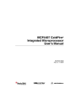
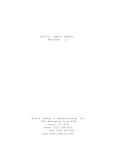
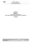
A summary of all the different mask timings is included in the Table 3 below.
Table 3. AC Timing Table
User Manual
Value
(nsec)
0H55J
1H55J
1J20C
2J20C
D2
2.0
-4.0
-4.0
-1.5
-1.5
T5
2.0
0.0
0.0
1.5
1.5
U6
2.0
0.0
0.0
1.5
1.5
U8
2.0
0.0
0.0
1.5
1.5
M13
2.0
0.0
0.0
2.0
2.0
P4
2.0
0.0
0.0
1.0
1.0
B11
2.0
0.0
0.0
1.0
1.0
B11a
2.0
-1.0
-1.0
0.5
0.5
B14
2.0
1.5
1.5
2.0
2.0
B14a
2.0
0.5
0.5
2.0
2.0
B14b
2.0
0.0
0.0
2.0
2.0
D1
5.5
5.5
5.5
7.5
7.5
Name
26.2 Workaround
•
The negative edge of pstclk can be used to sample the PST[3:0], DDATA[3:0] due to the negative
hold time specification for D2.
MASKS: 1J20C, 2J20C09/17/1999
27
MAC Fractional –1 * –1 Overflow Detection
Erratic
27.1 Description
In fractional mode, 32-bit results in the range [-1,+1) are generated in the accumulator of the MAC unit.
The bracket indicates that -1 is included and the parenthesis indicates that +1 is not. The product itself of
two inputs will always fall in this range except in the case of -1 5 -1 yielding +1. The +1 product is handled
as though no overflow has occurred and added to the accumulator. Only if the accumulator is initially
non-negative will overflow be signalled by setting the V condition code bit in the MACSR, and by
saturating the accumulator if the OMC bit (saturation mode) is set. If the product is to be subtracted from
the accumulator (MSAC instruction) then overflow will occur if the accumulator is initially negative.
MCF5307 Device Errata, Rev. 4.2
Freescale Semiconductor
19
MAC Fractional –1 * –1 Overflow Detection Erratic
There is an error in the detection of the overflow in the special case when the two 16-bit operands are
obtained from different halves of CPU registers. There is no problem with MAC instructions with 32-bit
operands or with MAC instructions with both 16-bit operands residing in the lower halves or both in the
upper halves of CPU registers. The execution of the following instructions may result in an erroneous V
(overflow) bit state if both operands = -1 (8000 hexadecimal):
mac.w
mac.w
msac.w
msac.w
Rx:u,Ry:l
Rx:l,Ry:u
Rx:u,Ry:l
Rx:l,Ry:u
If saturation mode is not enabled, only the setting of the V bit may be in error. If saturation mode is enabled,
the result in the accumulator may also be wrong.
27.2 Software Workarounds
If 16-bit operands MAC instruction operands are being used from different halves of different CPU
registers (y != x), and if the V bit is being checked or if the MAC unit is operating in saturation mode, then
any of the above instructions can be replaced with a three instruction sequence. For instance, the following
instruction:
mac.w
Rx:u,Ry:l
can be replaced with the following equivalent sequence:
swap
mac.w
swap
Rx
Rx:l,Ry:l
Rx
And the instruction:
mac.w
Rx:l,Ry:u
can be replaced with:
swap
mac.w
swap
Rx
Rx:u,Ry:u
Rx
Of course, the second swap instruction in each case should be removed if the MAC instruction specifies a
memory operand that is to be loaded into the Rx register.
Similar sequences can be substituted for the two failing MSAC.W instructions.
The case for 16-bit operands from different halves of the same CPU register (y == x) is slightly more
complicated. The instruction:
mac.w
Rx:u,Rx:l
can be replaced with:
cmp.lx,&0x80008000
bne.blabel1
mac.wRx:l,Rx:l
bra.blabel2
MCF5307 Device Errata, Rev. 4.2
20
Freescale Semiconductor
Data Inversion Triggers are Incorrect for Word and Longword Accesses
label1:
mac.wRx:u,Rx:l
label2:
Similar sequences can be used for the other failing instructions.
MASKS: 1J20C, 2J20C05/24/2000
28
Data Inversion Triggers are Incorrect for Word
and Longword Accesses
28.1 Description
The 5307 allows debug breakpoint triggers to be set on PC, and/or address, and optionally data compares.
The trigger definition register (TDR), and extended trigger definition register (XTDR) register in the 5307,
configures the breakpoint logic. In particular, TDR/XTDR[12:5] configures a data breakpoint.
TDR/XTDR[12:6] configures the size of the data to be compared to the data breakpoint register DBR
(and/or DBR1 in MCF5307) data value. Data breakpoints can be configured for byte-, word- or longword
reference sizes. However, the data inversion bit, TDR/XTDR[5], does not work as advertised. When
asserted, this bit is specified to enable data breakpoints to trigger for any access which does not match the
specified data value. The data inversion feature works correctly for byte-size accesses, but is incorrect for
16- and 32-bit references. There are scenarios where triggers should occur, but don't, for 16- and 32-bit
references.
28.2 Software Workaround
Do not use data inversion triggers/do not set TDR/XTDR[5] for word or longword breakpoints.
MASKS: 0H55J, 1H55J, 1J20C, 2J20C05/24/2000
29
Second-level Breakpoint Trigger Missed if it
Occurs on the Cycle Immediately after Assertion
of First-level Trigger
29.1 Description
The 5307 allows debug breakpoint triggers to be set correlating to PC, and/or address, and optionally data
compares. The configuration/status register bits, CSR[31–28], report breakpoint status, as follows:
• 0000 = No breakpoints enabled
• 0010 = Waiting for level 1 breakpoint
• 0100 = Level 1 breakpoint triggered
MCF5307 Device Errata, Rev. 4.2
Freescale Semiconductor
21
DMA Writes to UART Cause Transmission Errors
•
•
1010 = Waiting for level 2 breakpoint
1100 = Level 2 breakpoint triggered
A two-level breakpoint configuration means that the breakpoint cannot occur until the first-level trigger
has been matched and then after that the second-level trigger matches.
A boundary condition bug exists for a two-level breakpoint configuration:
If a two-level breakpoint is configured, with both trigger conditions occurring in adjacent processor clock
cycles, the second level trigger is missed and the trigger state incorrectly remains in the “waiting for trigger
2” state.
29.2 Software Workaround
Do not configure a two-level breakpoint; instead, configure two separate one-level breakpoints.
MASKS: 0H55J, 1H55J, 1J20C, 2J20C05/24/2000
30
DMA Writes to UART Cause Transmission Errors
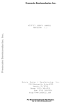
30.1 Description
DMA transfers from memory to the UART do not work properly. The DMA module configured for DMA
transfers to the UART:
DCR = 0x6052
Table 4. DCR = 0x6052
Bits
Name
Setting
Description
15
INT
0
No interrupt is generated at the completion of a transfer
14
EEXT
1
Enable external request
13
CS
1
Enable cycle steal
12
AA
0
No accesses are auto-aligned
11–9
BWC
000
DMA has priority
8
SAA
0
Dual address mode
7
S_RW
0
Not valid when SAA=0
6
SINC
1
Source address increments
5–4
SSIZE
01
Size of source bus cycle = byte
3
DINC
0
Destination address does not increment
2–1
DSIZE
01
Size of destination bus cycle = byte
0
START
0
The UART DREQ kicks off the DMA transfer
The UART is configured to assert an internal interrupt when the transmitter is ready (UIMR = 0x01 and
UISR = 0x01). DREQ is connected internally to the UART interrupt pin. When the UART asserts an
MCF5307 Device Errata, Rev. 4.2
22
Freescale Semiconductor
DMA Single-Address Access Mode and Cycle-steal Mode do Not Work Together
internal interrupt, the DMA initiates a single read/write cycle. The problem stems from DREQ not being
negated fast enough thus allowing a second DMA transfer right after the first when the transmit buffer
(UTB) of the UART isn't ready yet.
If the first byte hasn't been completely transmitted and the UTB (transmitter buffer) is still full, the second
byte transfer has nowhere to go and is discarded. For example if a string = “0123456789” is transferred
via the DMA to the transmit buffer of the UART, the UTB receives only “0248” and consequently only
0248 is sent out of the UART.
30.2 Software Workaround
Use the CPU to write to the UART transmitter buffer.
MASKS: 0H55J, 1H55J, 1J20C, 2J20C05/24/2000
31
DMA Single-Address Access Mode and
Cycle-steal Mode do Not Work Together
31.1 Description
An enabled DMA channel performing a single address access and a cycle steal, interprets a request for
another channel as a request for itself, performing an errant access. The intended access does occur after
the errant access.
31.2 Software Workaround
Don't use single address access mode in cycle-steal mode.
MASKS: 0H55J, 1H55J, 1J20C, 2J20C05/24/2000
32
DMA Channel Arbiter Hangs in Round-robin
Mode
32.1 Description
In the following scenario, the DMA channel arbiter may hang:
• Round-robin mode (MPARK[PARK] = 00)
• DCR[BWC] = 000
• Simultaneous access by DMA and core while the arbiter is selecting the external master (master
0).
When the bus grant is removed or when the SDRAM is performing a PAL (precharge), a hold is asserted
to the arbiter, putting it in a park on external master mode. When the hold is removed, if both core and
MCF5307 Device Errata, Rev. 4.2
Freescale Semiconductor
23
Processor Status Reporting Anomaly during Debug Exception Processing
DMA want the bus and DCR[BWC] is set to have priority, the arbiter hangs, causing the external bus to
hang.
32.2 Software Workaround
•
•
Set PARK = 01 (park on ColdFire core) or 10 (park on DMA).
Set BWC bits ≠ 000.
MASKS: 0H55J, 1H55J, 1J20C, 2J20C05/24/2000
33
Processor Status Reporting Anomaly during
Debug Exception Processing
33.1 Description
If the ColdFire debug module is configured to generate a debug interrupt exception in response to a
breakpoint trigger, the processor responds by taking a special exception. While processing this exception,
the debug module is supposed to output a contiguous stream of PST[3:0] = 0xD values until the exception
completes and control is passed to the instruction defined by the interrupt vector. This change-of-flow is
signaled by PST[3:0] = 0x5, which marks the end of the exception processing. The only allowable
deviations to the PST[3:0] = 0xD stream are operand markers (PST[3:0] = 0xB) associated with operand
captures during the writing of the exception stack frame.
If operand writes are being captured, there is the possibility that the stream of PST[3:0] = 0xD values is
non-contiguous, with PST[3:0] = 0x0 values incorrectly inserted into the output stream.
It is important to note that the processor's operation is perfectly correct throughout this sequence; it is the
potential occurrence of extraneous PST[3:0] = 0x0 values that is the error.
33.2 Software Workaround
•
•
Disable the capturing of operand writes if debug interrupts are enabled,
Simply ignore PST[3:0] = 0x0 values occurring during a debug interrupt. Let the debug interrupt
exception processing be defined from the initial PST[3:0] = 0xD until PST[3:0] = 0x5.
MASKS: 0H55J, 1H55J, 1J20C, 2J20C05/24/2000
MCF5307 Device Errata, Rev. 4.2
24
Freescale Semiconductor
Forcing Emulator Mode from Reset by Asserting CSR[13] does Not Work
34
Forcing Emulator Mode from Reset by Asserting
CSR[13] does Not Work
34.1 Description
The ColdFire debug architecture defines a control bit in the Configuration/Status Register (CSR) which
specifies the processor should begin execution in emulator mode. After reset is negated, the processor
samples for certain conditions (for example, the assertion of the breakpoint input signal) before beginning
reset exception processing. A typical sequence may involve the assertion of the breakpoint signal
immediately after the negation of reset, followed by a BDM-controlled initiation of the microprocessor
and/or system. Once the BDM "go" command is received, the processor continues with reset exception
processing.
If bit 13 of the CSR is set during this initialization sequence, the processor is supposed to begin the reset
exception processing in emulator mode. Unfortunately in all ColdFire core designs, the assertion of
CSR[13] in this type of sequence does not force entry in emulator mode.
34.2 Software Workaround
Do not set bit 13 of the debug module's Configuration/Status Register. The quickest entry into emulator
mode after reset is created with the following sequence:
1. While in the BDM initiation sequence, program a debug breakpoint trigger event by an operand
reference to address 0x0 or 0x4. As part of this sequence, the debug interrupt vector must also be
initialized to the same address as the initial PC defined at address 4.
2. When the BDM "go" command is received by the processor, the reset exception processing
fetches the longwords at addresses 0 and 4 in "normal mode" and then a debug interrupt is
immediately generated before the first instruction is executed.
3. Execution continues in emulator mode.
MASKS: 0H55J, 1H55J, 1J20C, 2J20C05/24/2000
35
Corrupted Return PC in Exception Stack Frame
35.1 Description
When processing an autovectored interrupt an error can occur that causes 0xFFFFFFFF to be written as
the return PC value in the exception stack frame. The problem is caused by a conflict between an internal
autovector access and a chip select mapped to the IACK address space (0xFFFFXXXX).
35.2 Workaround
•
Set the C/I bit in the chip select mask register (CSMR) for the chip select that is mapped to
0xFFFFXXXX. This will prevent the chip select from asserting for IACK accesses.
MCF5307 Device Errata, Rev. 4.2
Freescale Semiconductor
25
Incorrect Debug Interrupts Triggered
•
•
Remap the chip select to a different address range.
Use external logic to provide external vectors for all interrupts instead of autovectoring.
MASKS: 0H55J, 1H55J, 1J20C, 2J20C01/22/04
36
Incorrect Debug Interrupts Triggered
36.1 Description
Extraneous PC breakpoint debug interrupts (vector 13) may occur when the RTE instruction is executed
at the end of a PC breakpoint debug interrupt service routine. PC breakpoint debug interrupts are enabled
based on the settings of the PBR and PMR registers when the TDR[TRC] is set to 10. When the RTE
instruction is executed at the end of the interrupt service routine, extra debug interrupts may occur.
36.2 Workaround
In the debug interrupt service routine:
1. Clear the TDR
2. Once cleared, the TDR can be reprogrammed with the original value
3. Execute the return from exception (RTE)
MASKS: 0H55J, 1H55J, 1J20C, 2J20C08/02/04
37
Revision History
Table 5 is a revision history for this document.
Table 5. MCF5307 Processor Errata Change HIstory
Revision
Date
Change History
Rev 1.0
04/9/1999
Initial Errata.
Rev 1.1
04/21/1999
Edit - Errata #4.
Rev 2.0
06/17/1999
Add - 1J20C Mask.
Rev 2.1
08/18/1999
Add - Errata #25.
Rev 2.2
09/01/1999
Documentation Fix:
• Include description for Errata #23.
Rev 3.0
09/17/1999
Add - 2J20C Mask.
Add - Errata #26.
Rev 3.1
12/10/1999
Edited - Errata #13 Workaround.
Edited - Errata #15 Workaround.
Rev 4.0
05/23/2000
Add - Errata #27 - #34
Rev 4.1
01/22/04
Add - Errata #35
Rev 4.2
08/0204
Add - Errata #36
MCF5307 Device Errata, Rev. 4.2
26
Freescale Semiconductor
Revision History
THIS PAGE INTENTIONALLY LEFT BLANK
MCF5307 Device Errata, Rev. 4.2
Freescale Semiconductor
27
How to Reach Us:
Home Page:
www.freescale.com
E-mail:
support@freescale.com
USA/Europe or Locations Not Listed:
Freescale Semiconductor
Technical Information Center, CH370
1300 N. Alma School Road
Chandler, Arizona 85224
+1-800-521-6274 or +1-480-768-2130
support@freescale.com
Europe, Middle East, and Africa:
Freescale Halbleiter Deutschland GmbH
Technical Information Center
Schatzbogen 7
81829 Muenchen, Germany
+44 1296 380 456 (English)
+46 8 52200080 (English)
+49 89 92103 559 (German)
+33 1 69 35 48 48 (French)
support@freescale.com
Japan:
Freescale Semiconductor Japan Ltd.
Technical Information Center
3-20-1, Minami-Azabu, Minato-ku
Tokyo 106-0047, Japan
0120 191014 or +81 3 3440 3569
support.japan@freescale.com
Asia/Pacific:
Freescale Semiconductor Hong Kong Ltd.
Technical Information Center
2 Dai King Street
Tai Po Industrial Estate
Tai Po, N.T., Hong Kong
+800 2666 8080
support.asia@freescale.com
For Literature Requests Only:
Freescale Semiconductor Literature Distribution Center
P.O. Box 5405
Denver, Colorado 80217
1-800-441-2447 or 303-675-2140
Fax: 303-675-2150
LDCForFreescaleSemiconductor@hibbertgroup.com
Information in this document is provided solely to enable system and
software implementers to use Freescale Semiconductor products. There are
no express or implied copyright licenses granted hereunder to design or
fabricate any integrated circuits or integrated circuits based on the
information in this document.
Freescale Semiconductor reserves the right to make changes without further
notice to any products herein. Freescale Semiconductor makes no warranty,
representation or guarantee regarding the suitability of its products for any
particular purpose, nor does Freescale Semiconductor assume any liability
arising out of the application or use of any product or circuit, and specifically
disclaims any and all liability, including without limitation consequential or
incidental damages. “Typical” parameters that may be provided in Freescale
Semiconductor data sheets and/or specifications can and do vary in different
applications and actual performance may vary over time. All operating
parameters, including “Typicals”, must be validated for each customer
application by customer’s technical experts. Freescale Semiconductor does
not convey any license under its patent rights nor the rights of others.
Freescale Semiconductor products are not designed, intended, or authorized
for use as components in systems intended for surgical implant into the body,
or other applications intended to support or sustain life, or for any other
application in which the failure of the Freescale Semiconductor product could
create a situation where personal injury or death may occur. Should Buyer
purchase or use Freescale Semiconductor products for any such unintended
or unauthorized application, Buyer shall indemnify and hold Freescale
Semiconductor and its officers, employees, subsidiaries, affiliates, and
distributors harmless against all claims, costs, damages, and expenses, and
reasonable attorney fees arising out of, directly or indirectly, any claim of
personal injury or death associated with such unintended or unauthorized
use, even if such claim alleges that Freescale Semiconductor was negligent
regarding the design or manufacture of the part.
Freescale™ and the Freescale logo are trademarks of Freescale
Semiconductor, Inc. All other product or service names are the property
of their respective owners.© Freescale Semiconductor, Inc. 2004. All rights
reserved.
MCF5307DE
Rev. 4.2
08/2004