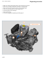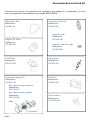
1
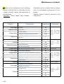
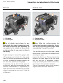
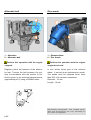
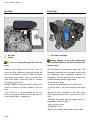
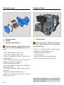
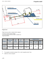
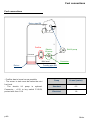
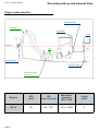
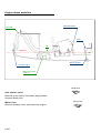
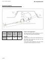
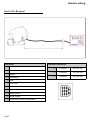
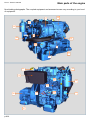
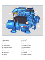
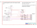
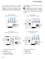
N2.14
English
Reference : 970 313 238
Date : 10/2007
Indice : A
This photograph does not
necessarily represent the
engine
Technical characteristics
N2.14 - Owner’s manual
Engine specifications
Cycle
4 strokes, Diesel
Number of cylinders / Arrangement 2 in line
Bore / Stroke
67 mm x 68 mm
Displacement
0,479 litres
Distribution
2 valves, gears
Compression rate
23/1
Atmospheric
Intake
Direction of rotation (from flywheel) Counter clockwise
Weight dry with gearbox
92 kg
Max. power*
10,3 kW (14 hp)
Rated rpm speed*
Idle rpm speed
3600 rpm
1050 rpm
No load rpm speed
3820 rpm
Specific fuel consumption
285 g/kW/h at 3600 rpm
Fuel supply
Injection
Indirect (E-TVCS)
Injection order
Injection timing
1-2
20° at 22° before PMH
Injection pump
BOSCH MD Mini type
Injection pressure
13,7 MPa
Lubrication
Engine oil
API CD-SAE 15W40 (temperate climat)
Engine oil capacity
1,9 litres
Cooling
Cooling
Dual circuit sweet water / sea water with heat exchanger or by
" keel cooling"
Neoprene rotor type
Around 2,7 liters, 50% water + 50% mixture of antifreeze and antiCoolant for heat exchanger version
corrosion agents
Electrical system
Alternator
12 V / 70 A
Seawater pump
Alternator belt tension
Deflection 8 mm at 5 daN
Battery capacity (min.)
100 to 110 A/h
Connections
Exhaust
40 mm
Fuel (suction and return
8 mm
Seawater
20 mm
Max. mounting angle
15° (dynamic)
These specifications are for marine pleasure only.
* For more information concerning your transmission,
refer to its specific manual.
p.A2
The recommended cruise speed is 200 rpm below rated
RPM speed.
*At engine flywheel, according to ISO 8665-1.
Maintenance schedule
Refer to the maintenance and servicing
Information given in italics refers to equip-
section in the manual for information on the
ment not necessarily forming part of your
regular servicing checks and operations to
engine.
be performed.
Gearbox (refer to specific manual for this
Operation : Control, Adjust, Clean, Replace
component)
Subset
Fuel supply
Exhaust elbow
Component
Fuel filter
Zinc anode
Tension of belts
Engine block
Tightening of attaching parts and clamps
I/R
R
I/A
Cables accelerator / reverse, Trolling, General
lubrication
Fuel supply
Air filter (cleaning kit)
I/C/R
Cooling
Seawater pump rotor
R
Starter (attachment)
I/A
Alternator (attachment)
I/A
Engine block
Fuel supply
Engine block
Electrical system
Lubrication
Cooling
Cleaning and protection of engine
Fuel pre-filter (cartridge)
Attachment of engine suspensions / alignment
Coolant change
Exchanger manifold or keel cooling
Cooling
I/A
R
Calibration of injectors
Every
200
hours or every
year
Every year
R
Engine oil (change)
Adjustment of valve clearance
Fuel supply
I/A/C
I
Cooling circuit (rinsing)
After 20 hours
then every 100
hours or every
year
I
Battery
Engine oil filter
Frequency
R
Control unit
Electrical system
p.A3
Operation
After 20 hours
then every 200
hours or every
year
I/A/R
C
Every 2 years
I/A
I/A/R
R
I/C
Calibrated plug of temperature exchanger
R
Thermostat
R
Every
400
hours or every 2
years
Inspection and adjustment of the levels
N2.14 - Owner’s manual
Oil level
Coolant level
1
2
2
1
1 - Oil gauge
2 - Oil filler port
1 - Coolant plug
2 - Expansion tank
The oil checks must always be performed with the engine stopped and cold.
Be careful, these fluids are flammable. Do
not smoke in the vicinity of these fluids
and do not allow for any sparks or flame in
the vicinity.
When filling the cooling system, the
coolant level must be checked after 10 minutes of use since the system purges itself
automatically. Top up if necessary.
Engine casing oil: remove the gauge, wipe
off the gauge and reinstall it in the gauge
tube. Pull out the gauge again and check the
oil level. It should be located between the
min. and max. positions on the gauge.
If necessary, top up the oil level: open the
air filler port, pour the recommended oil (see
technical characteristics in appendices) to
reach the max. level indicated on the gauge
without exceeding the max. level. Close the
oil filler port.
p.A4
Turn the filler plug up to its first stop to allow
the pressure in the system to escape before
removing the plug.
Inspect the fluid level. The level should be
between the lower edge of the filler neck
and the level pin (if equipped), respectively representing the minimum and maximum level in the expansion chamber.
Top up if necessary using a fluid comprising 50% water and 50% antifreeze.
Alternator belt
Zinc anode
1
1
2
2
1 - Alternator
2 - Alternator belt
1 - Exhaust elbow
2 - Zinc Anode
Perform this operation with the engine
stopped.
Perform this operation with the engine
stopped and cold.
Regularly check the tensions of the alternator belt. Tension the belt between the pulleys in accordance with the tension or deflection given in the technical characteristics
(appendices pA-2) using a DENSO meter.
A zinc anode forms part of the exhaust
elbow . It serves as an anticorrosion anode.
The anode must be replaced when more
than 50% of it has been consumed.
Diameter : 10 mm
Length : 16 mm
Non-binding photographs. The coupled equipment and accessories can vary according t o
your level of equipment.
p.A5
N2.14 - Owner’s manual
Air filter
Fuel filter
1
2
1
1 - Air filter
2 - Clamp
Be sure no impurities get into the engine.
Remove the clamp from the hose and remove the filter. Remove the spring inside the
filter. If necessary, clean the filter by washing it with soapy water. Then, rinse the filter
with clear water. Press the filter to remove
any water and to dry it.
NANNI DIESEL has designed a cleaning kit
which is suited to certain models of the air
filter.
Use of this kit is recommended on our engines to perform effective cleaning and ensure good engine « breathing ».
p.A6
1 - Fuel filter cartridge
Always sponge up any fuel which may
have spilled Observe the environment protection rules.
The fuel filter is a throw-away type filter. The
fireguard envelope and the water probe must
be preserved and reinstalled correctly (if
equipped). The fire guard must not come into
contact with the plastic purge screw.
-Close the fuel valve
-Unscrew the cartridge from the filter head
-Coat the seal of the new cartridge with clean
oil
-Screw the new cartridge on the filter head,
then tighten by hand by ¾ turn (do not use a
tool).
-Reinstall the probe and the purge screw (if
equipped). Check the seal
-Open the fuel valve
-Purge the circuit
-Start up the engine and check for any leaks
Sea-water pump
Engine oil drain
1
3
1
2
1 - Sea-water pump
2 - Impeller
3 - Sea-water pump gasket
Close the seawater intake valve as there
is a risk of water penetrating into the engine.
-Close the seawater intake valve
-Close the seawater pump cover
-Using a channel lock pliers, remove the
worn Impeller
-If the rotor shows any signs of cracks or
defects, it should be replaced
-Clean the parts preserved
-Fit a new rotor by applying a clockwise
rotary movement
-Install the seawater pump cover using a
new seal
-Open the seawater intake valve
-Start-up the engine and check for any
leaks in the circuit
1 - Oil drain pump
Hot oil can burn. Avoid any contact
with the skin. Observe the environment
protection rules.
-The oil is removed using a drain pump,
preferably: engine slightly warm
- Fully pump out all the oil
- Fill with new oil
- Check the oil level using the gauge
- Do not exceed the maximum level
Non-binding photographs. The coupled equipment and accessories can vary according t o
your level of equipment.
p.A7
Propeller shaft
N2.14 - Owner’s manual
r bo
Moto
a
15° m
.1 min
mini
0.15
Øx0
x
ats Ø
oats
S a il b
Coupling flange
x
Floating stuffing box
i
Flexible mount
Engine bed
Engine bed
Rigid structure able to absorb all the dynamical stress, and the engine weight.
It must be linked to the hull with a surface as
large as possible.
Engine RPM
Engine
Reduction
ratio
ØA
(mm)
Ø*
(inches)
L **
(meter)
2
22
12/13
1.20
N2.14
2.6
*
**
p.A8
22
14
Idling
Maxi rated
load
Maxi
without
load
1050
3600
3820
1.40
For propeller calculation please fill in in the ”propeller study” form
Maximum value accepted
Fuel connections
Fuel connections
H
Return pipe Ø8
Prefilter
Electric
lift pump
Std lift pump
Fuel tank
Mini level
Return
- Prefilter has to be as low as possible
- The return to tank must be below the mini
fuel level
- The electric lift pump is optional.
Connector : +12V to key switch P.15/54,
protect with fuse 1.5A
p.A9
Connector
Feeding pipe Ø8
Pump
H maxi (meter)
Standard
0.5
Electrical
1.8
Boiler
Sea water pick-up and exhaust lines
N2.14 - Owner’s manual
Engine under waterline
Sea-water pump
Hose ØE
Anti-siphon
Waterline
0.15m
2 m max
0.5 m min
max
0.15m
3m
Filter
ØE
ØD
Exhaust outlet
Sea cock valve
Water lock useful
volume V
Engine
ØD
(mm)
ØE
(mm / inches)
Max backpressure
(kPa / PSI)
V mini
(litre)
N2.14
20
40 / 1.57’’
10.5 / 1.523
5
p.A10
Engine above waterline
Sea-water pump
Filter
0.15m
x
ma
0.3 m min
3m
1.5 m max
Hose ØE
ØE
Waterline
ØD
Sea cock valve
Exhaust outlet
Water lock useful
volume V
All sail boat
Anti siphon valve
Must be at the end of raw water piping before
exhaust elbow inlet
Water lock
Must be always lower and near the engine
p.A11
Motor boats
Air requirement
N2.14 - Owner’s manual
Dynamical system
Engine
N2.14
p.A12
Engine air
Consum.
(m3/min)
0.7
Inlet
S1
(cm2)
110
Outlet
S2
(cm2)
40
Engine room temperature
Nor more than 50°C with a difference of 15°C
(20°C maxi) with ambient temperature.
Air flow
Fresh air inlet, on the front in the lower part of
the engine room and warm air outlet on the
back in the upper part.
Avoid short-circuit between inlet and outlet
in order to have a maximum air move.
Electric wiring
Eco3 / A3 / B3 panel
L
Connector
1 +
Extension references
L=
2 meters
970 304 162
L=
4 meters
970 302 665
L=
8 meters
970 302 666
2 3 Starter
4 Preheating
5 Stop
6 Oil sender
7 D+
8 Oil switch
9 Water switch
10 Water sender
11 Revolution counter (tachometer)
p.A13
Main parts of the engine
N2.14 - Owner’s manual
Non-binding photographs. The coupled equipment and accessories can vary according to your level
of equipment.
29
1
33
20
2
34
36
27
4
41
41
30
31
10
25
20
14
26
40
41
p.A14
11
34
22
24
30
31
20
10
14
40
26
1 - Alternator
26 - Oil gauge
2 - Alternator belt
27 - Oil filter
4 - Starter
29 - Heat exchanger
10 - Air filter
30 - Coolant filler port A
11 - Injection pump
31 - Coolant filler port B
14 - Acceleration control
33 - Freshwater pump
20 - Fuel filter
34 - Sea-water pump
22 - Water injection exhaust elbow
36 - Exchanger drain plug
24 - Oil filler port
40 - Gearbox
25 - Oil pump
41 - Flexible suspension
p.A15
25
The oil switch indicates a too low oil pressure in
the engine on the alert indicator 5.
Ref oil switch : 48 201 143
The water switch indicates a too high temperature of
the coolant on the alert indicator 6.
Ref water switch : 970 304 054
N2.14 - Owner’s manual
p.A16
The components indicated in italics (water sensor and oil sensor)
are optional equipment used with a more complete instrument
panel.
Wiring diagram
Instrumentation
This section presents the various
dashboards used to date with our marine
engines. In the event of modification of the
dashboards, we reserve ourselves the right
to present new models in the appendices.
Some panels are not available with the whole
range of engines.
The instruments shown often consist of
safety indicator lights. Take the necessary
time to become familiar with these instruments
and check them regularly when operating the
engine.
Eco3 panel
A3 panel
Dimensions 110 x 140 mm
Dimensions 205 x 120 mm
7
6
5
8
7
6
5
8
1
10
10
B3 panel
Fly Bridge model
Dimensions 220 x 145 mm
( example)
7
8
1
5
8
4
5
1
6
7
1 - Tachometer and hour meter
2 - Voltmeter
3 - Engine oil pressure
4 - Coolant temperature
5 - Low engine oil pressure
p.A17
6
10
10
6 - High coolant temperature
7 - Preheating
8 - Battery charge
10 - Switch on / off
Degassing procedure
N2.14 - Owner’s manual
• Make sure that the drain plugs (block, heat exchanger) are closed
• Open the vent plugs and B (heat exchanger, clamp by-pass)
• Open the filler plug 30 and fill with the recommended liquid
• Close the vent plug when the liquid escape from it
• Finish the filling of the exchanger
• Close the filler plug
• Fill half the expansion chamber by the filler plug 31
31
Expansion chamber
30
B
A
p.A18
Recommended on-board kit
Concerning the checks to be performed on installation (see chapter 4 on installation), you can
order the installation documentation from NANNI INDUSTRIES.
Alternator belt
Reference :
48 108 138
Complete injector
Reference :
970 307 587
Injector seal
Reference :
970 142 109
Engine oil filter
Reference :
970 302 697
Injector seal (O-ring)
Reference :
970 307 388
Fuel filter
Reference :
970 310 302
Glow-plug
Reference :
970 307 591
Sea-water pump kit
Reference :
970 307 749
Air filter
Reference :
970 301 330
Sea-water pump impeller
Reference :
970 434 013
Sea-water pump gasket
Reference :
970 504 028
Seal
Impeller
p.A19
Zinc Anode
Reference :
970 494 635