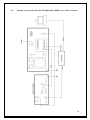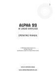
1
Instruction Manual OM4000A SHORTWAVE POWER AMPLIFIER WWW.OM-POWER.COM OM POWER, s.r.o. 93030 Báč 126, SLOVAKIA Contact : +421 905 321 410 e-mail : om-power@om-power.com 1 TABLE OF CONTENTS 1. 1.1. 1.2. 1.3. 1.4. 1.5. GENERAL INFORMATION Introduction Specification Parameters Protection Circuits Indicators 4 4 4 4 5 5 2. SAFETY INSTRUCTIONS 6 3. 3.1. 3.2. 3.3. GENERAL DESCRIPTION HF Part Power Supply Safety Devices 7 7 8 9 4. 4.1. 4.2. 4.3. 4.4. 4.5. 4.6. INSTALLATION Grounding Coaxial Cable I/O Box and Interface Mains Supply Cooling Remote Control 9 9 9 10 13 13 13 5. 5.1. 5.2. 5.2.1. 5.2.2. 5.2.3. 5.2.4. 5.2.5. 5.2.6. 5.2.7. 5.2.8. 5.2.9. 5.3. OPERATION Operation Elements Configuration of Power Amplifier TCVR Support Settings Connection with not supported TCVRs Communication Loss Antenna Switching Menu Bandpass Filter Settings Loading Factory Default Settings Mute Option LCD Settings Menu Operation in Manual Mode Tuning of Power Amplifier 13 14 16 17 18 19 19 20 20 21 22 22 22 6. 6.1. 6.2. 6.3. 6.4. MAINTENANCE Indication of Fault Conditions Fuse Replacement Tube Replacement Cleaning 26 26 27 27 27 2 7. 7.1. 7.2. 7.3. 7.4. 7.5. 7.6. 7.7. 7.8. 7.9. APPENDIX Example of connection with ICOM Example of connection with ELECRAFT Example of connection with YEASU Example of connection with Antenna Switch and BPF of connection USB Micro KEYER II with IC7800 or IC7700 Example of connection USB Micro KEYER II with another ICOM Example of connection USB Micro KEYER II with YAESU or ELECRAFT Example of connection PA with MicroHAM MKII, (MK2R+ etc.) CI-V output Block Diagram of the OM4000A power Amplifier 28 28 29 30 31 32 33 34 35 36 3 1. GENERAL INFORMATION 1.1. Introduction T he OM Power model OM4000A is a fully automatic power amplifier, designed for use on all short wave amateur bands from 1.8 to 29.7 MHz (including WARC bands) and all modes. It is equipped with a two pieces of ceramic tetrode FU728F. THE ADVANTAGES OF OM4000A Full compatibility with: ICOM, ELECRAFT, KENWOOD, TEN-TEC ORION, YAESU and Icom transceive protocol using by MicroHAM devices ( CI-V output ). Automatic switching between bands Automatic tuning within the band according to segments Automatic switching of band pass filter Automatic switching of antenna switches The possibility to use 2 different antennas within one band or segment 1.2. Specification 1.2.1. Parameters Frequency Coverage Power Output Input Power Input Impedance Power Gain Output Impedance Maximum Output SWR SWR protection Intermodulation distortion Suppression of harmonics Tubes Cooler Power supply Transformers Dimensions Weight Amateur Bands 1.8 – 29.7 MHz including WARC 4000W in SSB and CW, 3000W in RTTY, AM and FM Usually 60 to 90W for full Output Power 50 Ohm, VSWR < 1.5 : 1 17 dB 50 Ohm unbalanced 2:1 Automatic switching to STBY, when reflected power is 350W or higher 32dB below nominal output < -50 dBc 2x FU728F Ceramic tetrode Centrifugal blower + Axial blower 2 x 230V – 50 Hz one or two phases 2 pcs of toroidal transformer 3kVA 485 x 200 x 455mm (width x height x depth) 46 kg 4 1.2.2. Protection Circuits There are 11 special protection circuits used in the amplifier. They are activated when one or more of next parameters exceed defined values or some unwanted occasion occurs. VSWR too high Input power too high Output power too high Plate voltage too low Anode current too high Screen current too high Grid current too high Mistuning of PA Hot switching protection Soft start for protecting your fuses “switch-on blocking “ at opened amplifier 1.2.3. Indicators There are couples of LED and bar graph indicators visible on the front panel to inform you about value of some parameters or operation status: Bar graph indicators Power output - 50 LEDs Reflected power - 20 LEDs Ig2 current - 10 LEDs Anode voltage, anode current, tuning - 30 LEDs LED Indicators Current at control grid (Ig1) - 2 LEDs WAIT - preheating of tube (150 sec.) STBY - standby OPR - operation mode FAULT - failure, switching off for abt. 2 sec. INHIBIT - operating condition ANT 1 - which ANT is in use ANT 2 - which ANT is in use ANT - ANT selection Buttons UP – DWN MAN AUTO TUNE SET OSD Indicator LCD Display 2 x 16 characters - listing in menu - manual operating - automatic operating - tuning – confirms selected parameter 5 2. SAFETY INSTRUCTIONS WARNING! DANGEROUS HIGH VOLTAGE INSIDE! The power amplifier is using high voltage up to 3400V DC, which is very dangerous for human life! Read next safety instructions carefully first, before you will start to install and operate power amplifier! NEVER VIOLATE NEXT RULES! WARNING! NEVER ALLOW CHILDREN to play around PA or to touch power amplifier or connected cables in working condition, or to push anything into the case holes! WARNING! The amplifier contains high voltage circuits. Never turn the amplifier on without the upper lid in place. DO NOT ATTEMPT TO SHORT OR BYPASS safety switch under upper lid! WARNING! The OM4000A amplifier can be operated ONLY if both of supply cables are connected! The amplifier reaches optimal parameters in 2 phase’s system, if you do not have 2 phases, connect both mains cords into the same phase. WARNING! The OM4000A amplifier is neither to be used in a WET or HUMID environment nor to be exposed to RAINFALL! WARNING! Do not turn the amplifier ON without having connected the ANTENNA or properly rated DUMMY LOAD! A hazardous HF voltage may build up on the antenna connector after turning the amplifier on with no antenna or dummy load connected! WARNING! Before opening the upper lid of the amplifier make sure that power supply has been disconnected AT LEAST 5 minutes allowing the electrolytic capacitors to discharge fully. Disconnect power cord from the outlet! 6 CAUTION The amplifier must be installed in such a way that free flow of hot air from the tube is allowed. The amplifier must not be installed in a constrained surrounding (i.e. tight shelves etc.). During long time operation ventilation grid can reach high temperature. Do not touch the top cover of the PA in these places during operation. CAUTION The amplifier must be properly grounded during operation. CAUTION During operation the amplifier must be installed in such a way that the rear side remains accessible. CAUTION The amplifier is an A category product. In a household it can influence other electric appliances. In such cases the user is to take proper actions to mitigate this disturbance. CAUTION Make sure that all screws holding the case together are properly in place and tightened before carrying the amplifier with the handles! CAUTION Read this manual carefully. Fallow all of instructions during installation and operation to avoid damage to the amplifier not covered by manufacturer´s warranty! Do not attempt to perform any change of hardware or software! 3. GENERAL DESCRIPTION 3.1. HF part T his amplifier is using two pieces of ceramic tetrode FU728F in a grounded-cathode circuit (input into control grids). OM4000A amplifier achieves excellent linearity by the voltage stabilization of the control grid bias and the screen voltage. The power input is given to the control grids, using a broadband input circuit with an input impedance of 50 Ohms. This adaptable input circuitry ensures a good input SWR (better than 1.2:1) on all amateur bands. 7 The output of the amplifier is a Pi-L circuit. The ceramic capacitor for TUNE and LOAD are divided. This enables the amplifier to be tuned exactly and makes it possible to easily return to the previously set positions after band changes. Top view on the opened OM4000A Tetrode FU728F Output Pi-L Circuit PWR Meter Tuning Capacitor Blower Switch-ON Board Subpanel Power Supply Board 3.2. Power Supply P ower supply of the amplifier is comprised of two of 3 kVA toroidal transformers. A soft start is provided using relays and resistors. The high anode voltage is made by combining 8 x 420 V (total 3360V) @ 2.5A. Each has its own rectifier and filter. In the high voltage circuit, safety resistors are employed to protect the amplifier against overload. The source for screen grid is regulated by parallel stabilization with BU941 NPN Darlington transistors and delivers a voltage of 350V at 200mA. The -120V for the control grid is regulated with Zener diodes. 8 3.3. Safety Devices Control and monitoring circuits ensure control and safety during malfunctions of the PA. These are on the Control board, which is located on the chassis subpanel. 4. INSTALLATION NOTE Read this chapter carefully prior you will start installation. Before unpacking inspect shipping woody container first, if it is not damaged. Keep all of packing parts for possible future shipment. Check unpacked power amplifier. If you find some damaging, contact your dealer immediately to keep full warranty. During installation go step by step according to next parts. 4.1. Grounding CAUTION The amplifier has to be grounded properly! Connect the screw on the rear panel of the amplifier to your local grounding system with a copper cable; use a cross-section of 4 mm2 at least. Connect your transceiver to the same grounding system of your shack carefully! Use minimum length cables and make certain that the connections are both physically and electrically sound. With poor grounding, you may risk damaging your equipment, having problems with TVI/BCI or your transmitted signal may be distorted. 4.2. Coaxial Cable The output of the transceiver is to be connected to the input of the amplifier via RG58 or similar cable. For the connection between the power amplifier and the antenna, RG213 or similar coaxial cable suited for high power is recommended. Both the INPUT and OUTPUT SO-239 sockets with Teflon insulation is used. 9 Rear view of the amplifier OM4000A AC Sockets REMOTE Fuses I / O Interface OUTPUT INPUT 4.3. I/O Box and Interface Control of Amplifier and communication with TCVR as well as Antennas / BPF switching can be done via the rear panel I/O Interface. Control cable maintains TX / RX switching of the PA (TX GND). The cable is shielded. On the side of the power amplifier a CINCH-socket is used. On the side of your transceiver you have to use a socket suitable for this transceiver. During transmitting the middle pin is connected to the ground. The relays of the OM4000A have to be switched earlier than HF is applied (cold switching). Modern transceivers they have a time delay between PTT switching and power output. CAUTION If you are using and older transceiver or transmitters without time delay, we recommend to connect the PA in such a way that the transmit/receive switch (foot switch for example) is connected with the KEY IN socket of the amplifier. The KEY OUT socket is to be connected with the PTT socket at the transceiver. The amplifier is equipped with two safety devices, which ensure that the output relay is not switched under power mistakenly (hot switching). 10 KEY IN RCA Phono - Input signal PTT switching voltage / current 5V /2 mA) KEY OUT RCA Phono - Output signal PTT (maximum switching of 30V / 50mA) CI-V Mono 3.5mm Jack for connection of ICOM TCVRs or devices that provide compatible CI-V protocol. Correct baud rate is important. TCVR DB9 serial port RS232 for KENWOOD, YAESU and ELECRAFT TCVRs. Correct baud rate and type is required for successful operation. If both CI-V and TCVR cables are connected then CI-V disables RS232. Otherwise selection of interface is done via TCVR type. PC DB-9 RS232 port is used for communication with your PC. Please use setting you would normally use if using direct TCVR – PC connection. ALC RCA Phono – Automatic Level Control is used when tuning the PA to block drive level. BYPASS COM Connector (5.5/2.1mm) allows you to connect an external 12V DC power supply (rated at 200mA max.), which allows independent communication between the PC and the TCVR. It means the ability to communicate even if the PA is turned OFF. External source is separated from the internal supplying; this means that it can remain permanently connected to the PA. CAUTION! We only recommend using ALC feature while operating RTTY, FM and other 100% duty modes. 11 CONTROL The CONTROL socket is a single DB-15 connector that provides many connections to the amplifier from your transceiver. Use shielded cable for all connections to this connector. You will need to fabricate a cable with the proper connector for your transceiver or use individual connectors as described below. PIN OUT: 1. 2. 3. 4. ALC Out NC INHIBIT Control voltage TX INHIBIT for Yaesu and Elecraft – this supersedes ALC output 5. NC 6. KEY OUT 7. NC 8. KEY IN 9. – 15. GND ANT & BPF SW DB-25 is used for switching of external HP BPF or external Antenna Switch. Maximum switching of 30V / 0.5A is possible. PIN OUT: 1. antenna port 1 2. antenna port 2 3. antenna port 3 4. antenna port 4 5. antenna port 5 6. antenna port 6 7. antenna port 7 8. antenna port 8 9. antenna port 9 10. antenna port 10 11. COMMON port of ANT SW 12. NC 13. GND 14. BPF 160m 15. BPF 80m 16. BPF 40m 17. BPF 30m 18. BPF 20m 19. BPF 17m 20. BPF 15m 21. BPF 12m 22. BPF 10m 23. COMMON BPF port 24. NC 25. GND 12 4.4. Mains Supply WARNING! The power Amplifier OM4000A has to be connected TO THE MAINS WITH BOTH CABLES! The amplifier reaches optimal parameters in the system with 2 phases. Every phase has to be able to deliver 3 kVA. If you do not have 2 phases system, connect both mains cords into the same phase. In such a case the amplifier can´t deliver full power output. CAUTION Be sure you got PA with properly terminated line cable, corresponding with your power system’s outlet. If not, contact your dealer. In such a case you should make the necessary changes using a licensed electrician. CAUTION Be sure that your power system is correctly wired and properly rated! To use adequately sized and connected grounding system is also very important. 4.5. Cooling CAUTION The amplifier must be installed in such a way that free flow of hot air from the tube is allowed. Do not obstruct air intake and exhaust areas of the PA. The centrifugal blowers provide the necessary cooling of the amplifier, even during long contests. The main blower is activated by switching the PA on and it is turned off when cooling is finished (approx. 1-5 min after switching off the PA depending on the temperature of the tube). The supplemental fan is turned on depending on the temperature of the air exiting from the amplifier. It is switched on at 70°C and switched off at 60°C. 4.6. Remote Control Control of the amplifier is possible remotely by using REMOTE BOX (optional). Connection is done by REMOTE socket, maximum cable length should be 10 meters. 5. OPERATION WARNING! Before switching PA on, make sure that amplifier is grounded, antenna or dummy load is connected, and line cord is putted to the outlet. 13 CAUTION Before switching PA on, check all connections between PA and TCVR. CAUTION Do not turn PA on for at least 2 hours after unpacking it and locating in its operating location. Especially when amplifier is moved from a cold place to a warm one because not visible condensation may develop, and this could result in damage to the high voltage circuits of the PA. CAUTION Never try to change antenna output during a transmission to avoid warranty loss. NOTE When you decide to have a short operating break, place the amplifier in the standby mode rather than switch it off. 5.1. Operation Elements There is couple of operational elements accessible or visible on the front panel. 14 TUNE Anode capacitor for tuning, tuning of higher frequencies to "0", lower frequencies to “100”. LOAD Output capacitor tunes antenna load resistance to amplifier. Capacity is low at „100“ and high at "0" on the scale. OFF You switch off the amplifier by pressing this button. ON You switch on the amplifier by pressing this button. After 3 min. of warm-up delay, amplifier will be ready for operation. OPR/STBY „OPERATE“ sets the amplifier ready for transmit operation. In STBY, if WAIT-LED is on or the amplifier is OFF, the amplifier is in bypass-mode and your transceiver is directly connected to the antenna. Maximum allowed power in bypass mode is 400W. RF OUTPUT Bar graph – shows output power . REFLECTED POWER Bar graph – shows reflected power from the antenna. Maximum level is 350W otherwise amplifier switches to STANDBY mode. Ig2 Bar graph – measures the current of the second grid from -80mA to +120mA. HV/IP/TUNE Bar graph – measure the anode voltage, anode currency or tuning of the amplifier. 15 INHIBIT Indicates interruption of transmission during the tuning process of the PA. If indicated by RED LED then PA is in STBY mode. If during a retune operations within the same BAND, then the PA will retune according to the frequency of the transceiver. When changing the BAND – INHIBIT will stay lit until the KEY IN is released and the tuning process will start. After that PA is automatically ready for operation. ANT, ANT1, ANT2 The amplifier is capable of automatic antenna switching (ie. 80m CW and 80m SSB can be split between two antennas). The amplifier will automatically select desired antenna by selecting last used antenna on a given frequency. SET button for: - MAIN MENU Confirmation of selection Saving of selected value Saving of tuning parameters TUNE Push button for selection of TUNE mode AUTO Push button for selection of AUTOmatic mode MAN Push button for selection of MANUAL mode DWN / UP Push button for selection of band, segment or parameter 5.2. Configuration of Power Amplifier W hen the ON button is pressed the amplifier will start to heat the final amplifier tube. During the warm-up period, the STBY and WAIT LEDs will be illuminated. If a transceiver is connected to the correct port and all communication settings are right, the operating frequency, AUTO, and the type of transceiver will be indicated on the alphanumeric display. After successful heating of the TUBE you can enter operating mode by pressing the OPR button. 16 mmm Example of Automatic mode with ICOM TCVR. Type of supported TCVR and working frequency is visible on the display. AUTO LED is ON 5.2.1. TCVR Support Settings mmm Supported transceivers : ICOM, ELECRAFT, KENWOOD, TEN-TEC, ORION, YAESU. Press SET button and scroll UP/DWN to CHOOSE TCVR mmm Confirm CHOOSE TCVR by pressing SET again and scroll UP / DWN to your transceiver type. Confirm the selection by pressing SET mmm Continue by selecting Baud Rate. Press SET button and scroll using UP / DWN to BAUD RATE. Press SET again. Baud rate for TCVR – PA communication is shown on the display. 17 By scrolling UP / DWN select desired Baud Rate which must be the same as baud rate used by your transceiver (please refer to your transceiver user manual). To confirm your selection press SET. When using Yaesu TCVR you need to configure the STOP BIT parameter correctly and confirm selection with SET. The communication settings menu can be left by pressing the AUTO button. The amplifier will enter AUTO mode only if all settings are correct and connection has been established with your transceiver. You can verify that the correct frequency and transceiver type is shown on the LCD display. 5.2.2. Connection with not supported TCVRs For communication with TCVRs, that are not supported by OM4000A (for example JST-245 and older types of Kenwood), an external IF-232 converter is to be used. You can also use devices from several companies that produce compatible CI-V output which deliver frequency information in ICOM format through the CI-V output. Then the PA will be connected in the following configuration: JST-245 <> DB37- JST-245 cable <> MKII ( or other device which has a CI-V output ) <> PC. OM4000A is connected to the CI-V output of the CI-V device (MicroHam for example). mmm Confirm CHOOSE TCVR by pressing SET again and scroll UP / DWN to your transceiver type. Confirm the selection by pressing SET. mmm TCVR is connected via CI-V of MKII. Transceiver frequency is visible on the display. 18 5.2.3. Communication loss If TCVR is not connected or communication settings are incorrect, the message “COMMUNICATION LOST” will be displayed. You can still use PA by entering MANUAL mode (MAN Button) or by correcting the transceiver connection problem. mmm Example of Communication loss message. 5.2.4. Antenna Switching Menu If you have 3rd party external antenna switch connected to your amplifier ( i.e. MicroHAM TEN SWITCH), you need to configure the assignment of each port to a specific band /or antenna. mmm By pressing SET and scrolling to ANTENNA SETTINGS and confirming by SET you get current band and its antenna selection. mmm By scrolling UP / DWN you can select BAND which you want to assign to current ANTENNA selected. 19 mmm Then select how many antennas you want per current band (1 or 2) and always confirm your selection by pressing SET. mmm By scrolling UP / DWN you assign which PORT is used on your external antennas switch for this particular antenna. (ANT 1 ON PORT 01). Shall you decide to use 2 antennas for this band, then after confirming that with SET configuration continue to the other antenna selection / port selection. To finish Antenna switch configuration you can either press AUTO or MAN. 5.2.5. Bandpass filter switching Switching of external band pass filters is automatic and needs to follow pin out of BPF connector. For more details see Example of connection with antenna switch and BPF in the Appendix. 5.2.6. Loading factory default settings In the rare case of needing to restore factory default settings press SET and scroll using UP / DWN to LOAD DEF VALUES and confirm by SET. In the rare case of needing to restore factory default settings press SET and scroll using UP / DWN to LOAD DEF VALUES and confirm by SET. 20 Then select if you want to erase all settings (pressing TUNE) or just one setting value (SET button). In the case of resetting a single parameter use UP / DWN to select which option and confirm by SET. 5.2.7. MUTE option When operating the OM4000A with an Icom transceiver without TX INHIBIT for disabling TX, we recommend to block transmitting during tuning of the PA (mainly while operating FM /RTTY/ AM) using ALC connection. The ALC Input of your transceiver should be connected to the “ALC Out” of OM4000A. It is important to notice, that this is not a true ALC, only the transmitter will be blocked in this way during the process of PA tuning. Using SET and scrolling UP / DWN select SET MUTE and confirm it by SET. Then configure MUTE LEVEL for each band so it results in no power being transmitted by TX when performing TUNE procedure. 21 5.2.8. LCD Settings Menu Using SET and scrolling UP / DWN select SET LCD CONTRAST and confirm it by SET. By pressing Up or DWN you can vary contrast of the LCD display. Finally press SET to confirm selected value. 5.2.9. Operation in MANUAL mode To enter Manual mode of the PA press MAN. By pressing MAN repeatedly you select BAND and band segment. You can control the segment or band by scrolling the UP / DWN buttons. 5.3. Tuning of Power Amplifier T he OM4000A amplifier is operated in class AB. Thus it’s possible to obtain a maximum output power at excellent linearity. For this purpose the amplifier has to be tuned carefully. 22 WARNING! Before starting tuning you have to check if the right antenna or a 50 Ohms load resistance is connected at the antenna output! CAUTION The operation of a mistuned PA will cause malfunctions, the increase of grid current (the GRID-MAX-LED will light up) and problems with TVI/BCI. CAUTION The grid-current is shown with 2 LED diodes. It’s normal if the green LED is flashing or may be shining a little bit during peak operation. If you overload the amplifier the output power increases the grid current at very small rates and the red GRID-MAX-LED is shining and the safety devices switch the PA to STBY. You must decrease the input power. CAUTION In SSB mode you will have good output power if the green LED lights up a bit. The current of screen grid is measured and shown in a Bar graph Indicator. The amplifier has to be tuned in such a way that the current is between - 80 mA to +80 mA. At currents beyond these values the operating point will be shifted and IM-products will be rapidly increased. If a value of + 100mA is exceeded, the safety devices will switch the amplifier to STBY mode. 5.3.1. AUTO or MANUAL There are two possibilities of operation mode in OM4000A – AUTO or MANUAL. Normally, when you are using CAT interface connection between TCVR and PA, in AUTO mode PA will tune automatically to the TCVR frequency. If you do not have or use CAT connection, you will use MANUAL mode. You must manually select proper band and segment, corresponding to TCVR´s band and frequency. Then OM4000A will tune automatically to this manually selected band/segment. 5.3.2. Manual tuning instructions The OM4000A has been design to deliver maximum output power at 50 Ohms load. Parameters for PA auto tuning using real 50 Ohm loads are stored in the memory (factory default). To deliver maximum output power to a real load you need to adjust the tuning according to your real antenna impedance. This has to be done manually in TUNE mode (see 5.3.3. for details). First off all PA must be switched on. 1. Set the multimeter switch to the HV position 2. Set the OPR/STBY switch to the STBY position 3. Press the ON button 23 The amplifier is prepared for operation with the following automatic steps: Toroidal transformers are switched on step by step. The cooling blower for the final tube is switched on. The multi-meter bar graph measures the high voltage; the normal value is 3.3 KV The WAIT LED lights up. CAUTION After switching on, please confirm that the blower is operating properly. Air must be flowing from the ventilating aperture above the tube. If there is any concern, or no air flow, press the “OFF” button immediately! Heating of the tube takes about 180 seconds. After this time the WAIT LED goes out and the amplifier is ready for operation. Enter TUNE mode. Depending on the input power level and antenna parameters, two situations can occur. First, when your antenna parameters are close to real 50 Ohms, and input power not exceeds allowed maximum, PA stay in OPR mode and you will see the output power. You have to do just little adjustment (steps 8, 9, 12, 13) to get maximum output power. Second, if your antenna parameters are not very good and input power is higher than 15watts, safety devices will switch PA automatically to STBY. In such a case start with step 4, go thru all next steps. 4. 5. 6. 7. Reduce the power output of your transceiver to the minimum! Switch OPR/STBY to OPR position (OPR LED lights up). Choose the TUNE position of multimeter. Transmit and increase driver power to cca 10W. CAUTION If the input power is higher than 15W and the power amplifier is not correctly tuned, the safety devices will switch to STBY. The amplifier will automatically reset and switch back to OPR mode after approximately 2 seconds. Meanwhile, reduce the input power. 8. Set TUNE knob in such a way, that the TUNE-LED lights up maximum left (multimeter in TUNE position). 9. Set LOAD knob in such a way, that the TUNE LED on the TUNE scale lights up under the “V” sign. If it is possible to obtain the LOAD in 2 positions, set the position that is further to the right. 10. Repeat tuning several times according to 8 and 9, output power should be abt. 600W. 11. Increase the input power (to about 50-70W) until an output power of approximately 4000W will be reached. 12. Repeat steps 8 and 9. 13. Set TUNE knob to maximum output power (RF POWER LED lights up max. right). 24 After this procedure the amplifier is tuned correctly and ready to give 4000W output power in all operation modes. At optimal tuning and full output power a positive max. 80mA current goes through the second grid. On 24 and 28 MHz bands optimal tuning can be achieved when one or two LEDs are lit up to the right from the position “V”. If less output is desired you can simply decrease the load of the transceiver. CAUTION Should the amplifier demonstrate any malfunctions during tuning or should it not behave in accordance witch the description, interrupt the tuning procedure immediately and check the amplifier! Be sure to have not done any mistakes in choosing bands or TUNE/LOAD values! Be sure that VSWR is not higher than 2:1 and input power is LOW! After excluding possible human mistakes you will be able to work for long time with this amplifier! 5.3.3. Tuning Adjustment Entering the TUNE mode is done by pressing the TUNE button. The OM4000A then switches the transceiver to RTTY and sets the frequency to corresponding segment. By changing the values of TUNE and LOAD capacitors we tune the PA as per manual tuning instructions (see 5.3.2.). The optimally tuned amplifier will deliver full output without approaching the maximum Screen Current of 80mA! After tuning the amplifier save the settings by pressing SET and PA will automatically tune frequency of your transceiver to next band segment. Follow the same procedure for all bands and segments if needed. By pressing MAN or AUTO buttons PA and TCVR will return to standard operating mode. Dividing of bands into segments Band (MHz) 1,8 3,5 7 10 14 18 21 24 28 Width of the segments (kHz) 15 30 30 30 30 50 60 60 70 25 6. MAINTENANCE 6.1. Indication of fault conditions OM4000A has the following indication LED on the front panel: GRID MIN - indication of first gird current GRID MAX - max. First grid current exceeded HV - measuring of anode voltage by bar graph IP - measuring of anode currency by bar graph FAULT - fault OPR - amplifier in operation mode STBY - amplifier in standby mode WAIT - heating of tube after switching on the amplifier NOTE Should a fault condition appear during the tuning or operation of the amplifier, the safety circuits of OM4000A will react. The amplifier will be turned to STBY mode. After approx. 2 sec the control circuits will switch the amplifier back to OPR. CAUTION If the fault will repeat 3 times after each other the control circuits will turn the amplifier to STBY mode. Bringing the amplifier back to OPR mode is enabled by using the OPR/STBY switch only. After reaction of safety circuits the FAULT LED will be lit up for approx. 5 sec, depending on the nature of the fault. Flashing LED signalizes: IP - anode currency exceeded HV - low anode voltage FAULT - reflected output exceeded GRID MAX - first grid currency exceeded - screen grid currency exceeded GRID MAX + HV - maximum input power exceeded GRID MAX + IP - zero output power during tuning HV + IP - tuning fault, incorrect tuning of the Pi-L output circuit 26 In case your OM4000A amplifier is not working correctly, please contact the manufacturer or your dealer. Manufacturer’s contacts: 6.2. OM POWER, s.r.o. 93030 Báč 126, Phone : +421 905 321 410 e-mail : om-power@om-power.com SLOVAKIA Fuse Replacemeent The user is allowed to change mains fuses (6,3 x 32mm), accesible from the rear panel, only. In the case of interrupted fuse (fuses) inside the power amplifier, contact your dealer, please. 6.3. Tube Replacement In the case of vacuum tube damaging, contact the manufacturer or your dealer for ordering new one. You will get instructuions how to change tube and how to preset proper parameters, too. Be very careful, you will do it only on your own risk! If you are not comfortable to replace vacuum tube itself, contact your Service Center, please. 6.4. Cleaning To prevent damage of amplifier surfaces and plastic components do not use aggressive chemicals for cleaning. Do not open the amplifier for cleaning. Outer surface may be safely accomplished by using piece of soft cotton cloth moistured with clean water or window cleaner. 7. APPENDIX NOTICE The following block diagrams of connection between OM3500A and different types of TCVRs are also valid for use with OM4000A. 27 7.1. 28 7.2. Example of connection for ELECRAFT 29 7.3. Example of connection with Yeasu 30 7.4. Example of connection with antenna switch and BPF 31 7.5. Example of connection USB micro KEYER II with IC7800 or IC7700 32 7.6. Example of connection USB micro KEYER II with another Icom 33 7.7. Example for connection USB micro KEYER II with Yeasu or ELECRAFT 34 7.8. Example of connection PA with MicroHAM MKII, (MK2R+ etc ) with CI-V output 35 7.9. Block Diagram of the OM4000A Power Amplifier 36