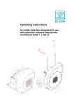
1
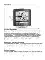
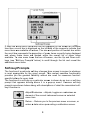
Load Cell Display & DLA1
Operating instructions
For Software Version 1.12
Stowe Marine Ltd.
235 Bentley Way
LYMINGTON
SO41 8JW
England
www.stowemarine.com
© Stowe Marine Ltd. 2010
The copyright of this manual is the property of Stowe Marine Ltd.
Product liability and safety warnings
Product liability
Stowe Marine Ltd. accepts no responsibility for the use and/or operation of this
equipment. It is the user’s responsibility to ensure that under all circumstances the
equipment is used for the purposes for which it has been designed.
Warning – electrical hazard
This equipment uses high voltage electrical power. Contact with high voltages may result
in injury and/or loss of life.
Warning - calibration
The safe operation of this equipment is dependent on accurate and correct calibration.
Incorrect calibration of this equipment may lead to false and inaccurate navigational
readings placing the vessel into danger.
Caution
The use of solvent based or chemical cleaners on Display will result in damage and
invalidate your warranty.
Caution
Display contains no user-serviceable parts. Repairs should only be made by an
authorised service centre. Unauthorised repairs or modifications may invalidate the
warranty.
1
EMC Directive 89/336/EEC
This product has been designed to be compliant with the above
Directive. Maximum performance, and compliance with the EMC
Directive, can only be ensured by correct installation. It is strongly
recommended that the installation conforms to the following
standards:
Small Craft – Electrical Systems:
A.
B.
ISO 10133 –Extra Low-Voltage DC Installations
ISO 13297 –Alternating Current Installations
ISO = International Standards Organization
Trademarks
All rights reserved. No part of this manual may be reproduced or transmitted in any form
or by any means including photocopying and recording, for any purpose without the
express written permission of Stowe Marine Ltd.
Information in this document is subject to change without notice. Stowe Marine Ltd.
reserves the right to change or improve its products and to make changes in the content
without obligation to notify any person or organisation of such changes.
Stowe, Dataline and Dataline GX are all trademarks of Stowe Marine Ltd. and may not
be used without the express permission of Stowe Marine Ltd.
Stowe is a registered trademark of Stowe Marine Ltd.
Dataline is a registered trademark of Stowe Marine Ltd.
NMEA is a registered trademark of the National Marine Electronics Association.
NMEA 2000 is a registered trademark of the National Marine Electronics Association.
The information contained in this manual is believed to be accurate at the time of going
to print but no responsibility, direct or consequential, can be accepted for damage
resulting from the use of this information. The manufacturers reserve the right to make
changes, without notice, to any of its products.
© Stowe Marine Ltd. 2010
2
Opera
ation
Display Soft-keys
s
The Dattaline GX has five
e Screen Soft-keyss that control all u
unit functions. Scre
een
Soft-key
ys are used for ch
hoosing screens, as
a well as navigatting through and
choosin
ng the various men
nu options. The fu
unctions of these ffive keys are
context--sensitive, and de
epend upon the sccreen being displa
ayed at the time a
soft-key
y is pressed. A popup menu showin
ng each soft-key’ss function appearss
just abo
ove the soft-key att the bottom of the
e LCD display. Th
here is also an
audible “beep” when any button is pressed
d to confirm the bu
utton press. This
beeping
g function can be disabled
d
within the SETUP MENU
Menu
u and Soft-ke
ey Prompts
When working
w
with the Dataline
D
GX functions and menus, tthere are many ways
w
to choo
ose options and enter
e
information. Many of the scre
eens that will require
your inp
put will also give you
y Prompts on how
h
to enter the in
nformation or cho
oose
options..
Menu
u Prompts
On men
nu screens wherre a number of different menu items are listed, the
currently selected menu item is denoted by
b bold print and a small cursor arrrow
next to it.
i
3
If there are more
m
menu itemss than can be disp
played on the scre
een at the same
time then a scroll bar is displayed on the left side
s
of the screen
n to indicate that
more items are
a available off-sscreen. The size and
a position of the
e dark box within
the scroll ba
ar represents the proportion
p
of men
nu items currently being displayed
and where these items are
e located within the overall list of menu items
available. To
o view menu item
ms that are off-scrreen, use the Up and Down softkeys (see “S
Soft-key Promptss” below) to scrolll through the listt and reveal the
additional menu items.
Soft-key
y Prompts
The function
n of a particular so
oft-key changes frrom screen to scrreen to whatever
is most app
propriate for the given screen. Th
his context sensittive functionality
provides you the greatest fle
exibility without the
t
need for num
merous functionspecific butto
ons for every taskk.
The function
n of a soft-key on a particular scree
en is shown by an
n icon or soft-key
prompt that appears directlyy above it in a pop-up
p
menu. Co
ommon soft-key
prompts are
e shown below alo
ong with descripttions of what the associated softkey’s functio
on is.
Adjust/C
Customise – Adjusts, toggles or cusstomises an
element of the current insstrument screen o
or selected
menu item.
Return – Returns you to the previous men
nu or screen, or
enters a data value upon
n exiting a calibrattion screen.
4
Decrease – Decreasses the setting of a selected menu
item
m.
Dow
wn – Moves the cursor
c
arrow down
n to select the nexxt
me
enu item in a list
Inccrease – Increasess the setting of a sselected menu
item
m.
Entter – Stores the se
etting of a selecte
ed function.
Up – Moves the curssor arrow up to se
elect the previous
me
enu item in a list.
Backlighting and
d Contrast
The bac
cklight intensity an
nd contrast settings for the Datalin
ne GX display can
n be
adjusted
d by briefly pre
essing the rightt-most soft-key whilst viewing any
instrume
ent display scree
en. Doing so causses the Lighting a
and Contrast Pop
p-up
Menu to
o appear at the bottom
b
of the LCD display. Press the soft-key dire
ectly
below the
t
soft-key prom
mpt for the adjusstment desired a
and that display will
immedia
ately adjust acccording to your selection. Conttinue making these
adjustm
ments until you have achieved the optimum vviewing settings for
readability. Press the sofft-key under the re
eturn symbol to le
eave the Lighting and
Contras
st Pop-up Menu and return to th
he screen you w
were viewing prior to
making the display adjustments.
5
Screen Selection
S
The Dataline
e GX displays insstrument data and
d information on sscreens selected
by the use
er. These screen
ns are accessed
d via the five sscreen soft-keys
positioned ju
ust below the LCD
D display.
The four leftmost soft-keys (K
Key 1 to Key 4) are
e factory configure
ed and will take
you directly to the pre-set scre
eens with only a single
s
key press. S
Successive
presses of each
e
of these keyss will cycle around
d the available opttions.
Screen selection
s
Flo
owchart
6
Page Lock
The Pa
age Lock facility allows a key to be locked to on
ne particular disp
play
screen, so that it may ea
asily be recalled at
a the push of a bu
utton. To activate the
Page Lock feature, simp
ply press and ho
old the Key you wish to lock for two
seconds
s until the Key symbol is displayed
d. To unlock a Keyy, press and hold the
Key for two seconds.
Main Menu
The MA
AIN MENU allows you to calibrate, configure, and cu
ustomise the Data
aline
GX acco
ording to your nee
eds and preferencces.
To acce
ess the MAIN MENU,
M
press and
d hold the rightm
most soft-key for five
seconds
s until the MAIN
N MENU appearrs. Use Up and Down soft-keyss to
highligh
ht individual menus and menu itemss.
7
Use the Adjust/Customise so
oft-key to select choices and/or ma
ake adjustments.
In some insttances, you may be
b required to con
nfirm a selection b
by pressing ENT.
Use the RET
TURN soft-key to return to previou
us/parent menus. When done with
all your cha
anges, press the RETURN soft-key again to exit from the MAIN
MENU to re
eturn to the displa
ay screen you we
ere viewing prior tto accessing the
menu.
Note In som
me instances, you may be required to confirm a selecction by
pressing ENT.
Setup Menu
The SETUP MENU is a sub menu
m
of the main menu and contain
ns the following
functions.
Beeper
This function
n enables and dissables the internall beeper from sou
unding each time
a soft-key is
s pressed. Audible
e alarm functionss remain unaffecte
ed. This function
will only adjjust the local uniit and the setting
g is stored in me
emory through a
power-off.
Use the Adju
ust/Customise soft-key to toggle th
he key press beep
per’s operational
status.
8
Language
Selectin
ng LANGUAGE fro
om the SETUP MENU
M
displays the
e LANGUAGE ME
ENU
screen. This menu allow
ws you to change the language use
ed by all the displlays
in a netw
worked system.
Select the desired langua
age by using the Up,
U Down, and Ad
djust/Customise softs
keys.
Mode
e
The Dataline GX Displayy has been designed for use with several modes. This
T
instructiion manual only covers
c
the ‘Load’ and ‘Forestay’ m
modes which mustt be
selected
d to operate as a Load Cell Displa
ay. To alter the d
display mode, sim
mply
press th
he Adjust soft-keyy to cycle through the available men
nu choices. Note that
after performing a ‘Resett’ the unit will power up in ‘Sail’ mod
de.
Demo
o
The Dataline GX can be
e configured to run an internal dem
monstration progrram,
which is
s useful for learnin
ng the operation of
o the display.
9
Units Menu
Selecting UNITS from the SETUP MENU produces the UNITS MENU screen.
This menu allows you to customise the displayed units. Selected units can be
‘tonnes f’, ‘kgf’ or ‘klbf’. The units selection does not affect the calculation and is
only used to set up the display title. The display must also be calibrated in the
units required.
Calibrate Menu
Selecting CALIBRATE MENU from the MAIN MENU produces the CALIBRATE
MENU screen. This menu allows you to calibrate the amplifier to the load pin in
the units required. Before entering the calibration figure it is IMPORTANT TO
REMOVE ALL LOAD from the pin to allow the amplifier to automatically carry
out the zero calibration as part of the automatic calibration procedure.
Load Cal Figure
The Load Cal Figure option allows you to enter the ‘Cal Equivalent’ figure from
the supplied Load Cell Calibration Certificate.
The current output from the amplifier is shown in the top of the display as
LOAD, which should be on or near zero with all load removed. The figure in the
middle of the display is the new calibration figure from the certificate and can be
in either ‘tonne f’, ‘kgf’ or ‘klbs’.
10
Simply adjust the calibration value by using the increment and decrement softkeys, and then press ENT to automatically calibrate and store the new zero and
calibration values in the amplifier. To exit the calibration page without
recalibrating, press the RETURN soft-key.
Bargraph Range
The Bargraph Range setting is used to adjust the maximum scaling for the
analogue bargraph indicator.
To adjust the maximum range, repeatedly press the ADJUST soft-key to scroll
through the pre-set limits. The pre-set limits are available as follows: 1-10 in
single units and then 15-50 in increments of 5 units.
Trip Relay Set
The trip relay setting is used to adjust the point at which the relay switches its
change over contacts.
To adjust the trip relay setting, adjust the trip set value by using the increment
and decrement soft-keys in either ‘tonne f’, ‘kgf’ or ‘klbs’ depending on the
11
chosen units entered during calibration, and then press ENT to store and
update the trip value in the amplifier.
Engineers Test Functions
There are two Engineers controls under the cover on the DLA1 which should
not be required under normal use. These functions relate to software version
1.00 only.
‘Set’ Pushbutton. When pressed, this button switches on the calibration resistor.
A properly functioning and calibrated system will output the calibration figure as
LOAD while the button is held pressed.
‘Adjust’ control is used to calibrate the battery voltage input.
12
Installation
A complete installation consists of mounting the Dataline GX and making all the
necessary connections.
Parts Supplied
Below is a list of the parts supplied by Stowe Marine; please ensure that all the
appropriate parts were included in your package:
• Dataline GX Display
• Dataplug Connector
• Cover
• This User Manual
• Installation Template
If any items are missing, please call Stowe Customer Support on +44 (0) 1590
610071.
Additional Tools and Items you’ll Need
You may need to order additional cabling to connect your Dataline GX to the
existing instrument system. To do so, you will need to take measurements of
several wiring runs. If it is determined that additional cabling is required, please
contact your local authorised Stowe Marine dealership who will be able to
supply the appropriate cabling. Next, carefully plan where you will be installing
the Dataline GX and where you will be routing any cables. Then, preferably,
pre-install the Dataline GX prior to measuring to ensure that you will have the
exact measurements prior to ordering.
When planning and measuring cable routes, measure along unobstructed wire
runs between the various points of connection. Round off each measurement to
the nearest 30cm (1’) and add additional length if uncertain.
If required, order cables and all other needed parts from Stowe Marine by
calling +44 (0) 1590 610071. In addition to the items above, you will also need
the following for installation and operation:
• A 64mm (2.5”) hole saw
• A hand drill and various drill bits
• Terminal-block screwdriver
• A ruler or measuring tape
• Pen or pencil
• Adhesive tape
• UV nylon mounting cable ties. Clamps may be used instead.
13
Mounting the Dataline GX
Bulkhead Mounting
Determining Proper Mounting Location
Place the unit in various locations to decide which is best for mounting. The
Dataline GX may have to be disconnected for service at some point during the
boat’s lifetime, so leave at least 100mm (4”) of clearance behind the unit for
releasing and removing its connectors.
14
Fixing Template
Overall size 110mm (4.33”) x 110mm (4.33”)
Fixing Hole Positions
70mm (2.75”) x 70mm (2.75”)
Cut Out for back recess 64mm
diameter (2.5”)
Drill 4mm clearance x 4
= 4.3mm (0.17”)
15
16
Mounting Unit
1. Locate a suitable, flat area of the bulkhead to mount the Dataline
GX.
2. Tape the Bulkhead Mounting Installation Template to the desired
mounting location.
3. Drill a 2.5mm (3/16”) hole at each of the four mounting hole
locations marked on the template.
4. Cut out the circular section marked in the centre of the template
with a 64mm (2.5”) hole saw. Remove template when finished.
5. Insert and tighten the four threaded 4.3mm (3/16”) studs into the
four holes located on the rear-side of the unit.
6. Pass the Dataline GX’s rear cable and connector assembly
through the main cut-out on the mounting surface.
7. Align the unit with the mounting holes in the front side of the
bulkhead and insert the unit and studs into the bulkhead. From
the rear-side of the bulkhead, place a thumbnut onto each
threaded stud and finger-tighten only. Excess studding may be
cropped off if desired.
17
Mountin
ng the Dataline GX in a Bulkhead
18
Electrical Connections
RED
WHT
BRN
GRN
BLK
1. If the display is being connected to a DLA1 Load Cell amplifier,
then connect the display to the colour coded connections in the
DLA1.
2. The correct positions for the different coloured wires are shown
on the rear label of the display and connect to the DLA1 as in the
table below.
Colour
DLA Terminal
Red
+12/24 Volts
White
NMEA O/P A
Brown
NMEA 1 I/P A
Green
NMEA 1 I/P B
Black
GND
19
3.. If the instrumen
nt is being conneccted to another insstrument
system, then th
he connections arre as shown in the
e table below:
Colour
Func
ction
Red
+12V
V ~ +24V Power In
n (500mA Fuse)
White
NMEA
A Signal In (A / + / Positive)
Brown
Not Connected
C
Green
NMEA
A Reference In (B
B / - / Negative)
Black
0V Po
ower In
4.. Check that the instrument functio
ons correctly.
Notes
•
•
•
•
•
Avoid running cables
c
along othe
er wires or cables that carry high
current or migh
ht cause EMI (elecctromagnetic interrference).
Examples are generator
g
leads or sparkplug wires. Such runs
could cause syystem interference
e or possibly even
n failure.
Do not over-tighten fixing screwss.
D40 or any solventt on any part of th
he instrument.
Do not use WD
Do not use sea
aling compound on
n the rear of the in
nstrument
casing.
00mm (12”) with ccable ties or
Secure Dataline cables every 30
ainless steel screw
ws.
clamps and sta
20
Specifications
Power
Voltage Input
Consumption:
9V to 24V d.c.
100mA (lights off)
125mA (lights on)
Circuit Protection
One 500mA fuse/breaker per unit (in installations using
an otherwise un-powered or inadequately powered Dataline)
Display Unit
Display Type
Backlight
Mounting
Construction
Dimensions
FSTN 4 Level Greyscale
128 x 160 pixels
Green LED with three user selectable levels and
Backlit keys
Bulkhead or Gimbal
High Impact ABS casing sealed with silicone gaskets
110mm (H) x 110mm (W) x 38.5mm (D)
4.3” (H) x 4.3” (W) x 1.5” (D)
Communication
Dataline
Baud
Proprietary Stowe Marine protocol based on NMEA
4800
Input Sentence
$YXXDR,G,xx.xx,,nnn<CR><LF>
xx.xx is Generic load in no particular units
nnn is sensor number from 001 to 008
sensor 001 is displayed as Forestay
$PSTOT,xxxx<CR><LF>
xxxx is ‘Trip value’ X 100
Output Sentences
$PTINC,xxxx<CR><LF>
xxxx is ‘Calibration equivalent’ X 100
‘Calibration equivalent’ can be found on the Load Cell
Calibration Certificate
$PTINT,xxxx<CR><LF>
xxxx is ‘Trip value’ X 100
Environmental
Operating Temperature
Storage Temperature
Enclosure Rating
-25°C to 75°C (-13°F to 167°F)
-30°C to 80°C (-22°F to 176°F)
IP67
22
Troubleshooting
If a problem cannot be identified or corrected, call Stowe Customer Support on
01590 610071.
Visual Inspection
If a problem is experienced with the Dataline GX system, such as lost data or
no data being reported from an installed sensor, first visually inspect the system
for the most likely causes, which include the following:
• Adequate power supply
• Loose connectors
• Bent connector pins
• Harnesses perforated by excessively tightened wire ties
• Faulty sensor/transducer/interface
Maintenance
Your Stowe Marine Dataline GX is designed to provide you with years of
trouble-free operation with virtually no maintenance. Follow the simple
procedures below to ensure that your Dataline GX continues to deliver top
performance.
If the unit comes into contact with salt spray, simply wipe the affected surfaces
with a cloth dampened in fresh water.
Do not attempt to repair the Dataline GX yourself. There are no user
serviceable parts inside, and special tools and techniques are required for
reassembly to ensure the waterproof integrity of the housings. Repairs should
be performed only by authorised Stowe Marine technicians.
Many requests for repair received by Stowe Marine involve units that do not
actually need repair. These units are returned “no problem found.” If you have a
problem with your Dataline GX, consult the troubleshooting guide before calling
Customer Support or sending your unit in for repair. The Dataline GX contains
several tools which can aid in determining if there is a problem and how to
isolate and repair the problem in many cases.
WARNING
Disassembly and repair of this electronic unit should only be performed by
authorised service personnel. Any modification of the serial number or attempt
to repair the original equipment or accessories by unauthorised individuals will
invalidate the warranty. Handling and/or opening this unit may result in
exposure to lead, in the form of solder.
23
Customer Support
If you have any questions, contact Stowe Marine Customer Support:
Telephone:
+44 (0) 1590 610071
Email:
support@stowemarine.co.uk
Two Year Warranty
We warrant to the original retail purchaser that Stowe Marine electronic
products have been manufactured free from defects in materials and
workmanship. This warranty is effective for two years from the product
manufacture date, except where Stowe Marine electronic products are used
commercially or in any rental or other income producing activity; then this
warranty is limited to one year from the date of original purchase for mechanical
and electrical products.
Stowe Marine products found to be defective and covered by this warranty will
be replaced or repaired at Stowe Marine’s option, and returned to the customer.
Items must be returned (freight prepaid) within the warranty period to the dealer
from whom such products were purchased, or directly to Stowe Marine’s
Lymington facility.
Stowe Marine’s sole responsibility under this warranty is limited to the repair or
replacement of product that is, in Stowe Marine’s opinion, defective. Stowe
Marine is not responsible for charges connected with the removal of such
product or reinstallation of replacement or repaired parts.
We will have no obligations under this warranty for any product which:
• was improperly installed;
• was used in an installation other than as recommended in our
installation or operation instructions or specifications;
• failed or was damaged due to an accident or abnormal operation
including racing, misuse or alterations outside our factory;
• was repaired or modified by entities other than Stowe Marine;
• was used on an engine/boat combination where the engine
horsepower exceeds the rating established by the boat
manufacturer;
• was used with other product(s) which, in Stowe Marine’s opinion,
are incompatible with the Stowe Marine product.
THIS WARRANTY IS EXPRESSLY IN LIEU OF ANY OTHER WARRANTIES,
OBLIGATIONS OR LIABILITIES ON THE PART OF STOWE MARINE AND
WILL BE THE CUSTOMER’S EXCLUSIVE REMEDY EXCEPT FOR ANY
APPLICABLE IMPLIED WARRANTIES UNDER ENGLISH LAW WHICH ARE
HEREBY LIMITED IN DURATION TO TWO YEARS FROM THE DATE OF
ORIGINAL PURCHASE. IN NO EVENT WILL STOWE MARINE BE LIABLE
FOR ANY INCIDENTAL OR CONSEQUENTIAL DAMAGES FOR BREACH OF
ANY EXPRESS OR IMPLIED WARRANTY RELATING TO THE PRODUCTS.
Stowe Marine products returned under this warranty must be tagged with the
customer’s name, street address, and phone number to ensure proper handling,
and returned freight prepaid to the selling dealer or to the appropriate Stowe
Marine manufacturing facility. User manual contains the facility return
addresses.
Customer Service
For Customer Service, please contact a Customer Service representative:
Telephone:
+44 (0) 1590 610071
Email:
info@stowemarine.com
Products should be sent to:
Stowe Marine Ltd.
235 Bentley Way
LYMINGTON
SO41 8JW
England
The Limited Warranty does not cover shipping costs to the Stowe Marine
Lymington facility, any costs for labour or otherwise related to product removal
or replacement, or any other costs of any nature without prior consent by Stowe
Marine Service in Lymington, UK. Parts, products and accessories made by
others are warranted only to the extent of the original manufacturer’s warranty
to Stowe Marine.
Stowe Marine tests 100% of the returned products at its facility.
Please call +44 (0)1590 610071 should you have any questions regarding
customer returns. The customer may also email Stowe Marine at
info@stowemarine.com
25