1
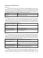
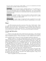
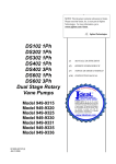
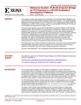
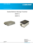
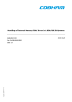
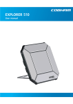
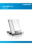
Cobham Aerospace FPGA and Radio Communication Capstone Project Harper Alfred Dan Baronsky Nick Rowe McKenzie Schmidt Kurtis Wachs 323-742-6078 928-445-0165 480-720-3026 907-982-9481 928-848-8068 ha73@nau.edu db459@nau.edu nr243@nau.edu mls398@nau.edu kew229@nau.edu Table of Contents Summary ......................................................................................................................................... 3 Problem Overview .......................................................................................................................... 4 Problem Statement ...................................................................................................................... 4 Diagram....................................................................................................................................... 4 Research Survey.............................................................................................................................. 5 Research Result ........................................................................................................................... 5 Research References ................................................................................................................... 5 Requirements and Specifications: ................................................................................................... 6 Mechanical .................................................................................................................................. 6 Electrical ..................................................................................................................................... 6 Software ...................................................................................................................................... 6 Environment ................................................................................................................................ 6 Documentation ............................................................................................................................ 7 Testing......................................................................................................................................... 7 General ........................................................................................................................................ 7 Design ............................................................................................................................................. 8 Description .................................................................................................................................. 8 Analysis....................................................................................................................................... 8 Parts Chosen................................................................................................................................ 8 Constraints .................................................................................................................................. 8 Budget ............................................................................................................................................. 9 Schedule and Deliverables .............................................................................................................. 9 Schedule ...................................................................................................................................... 9 Deliverables .............................................................................................................................. 10 Appendix A-Second Semester Schedule ...................................................................................... 11 2 Summary Proposed Design The purpose of the project is to design a test setup to allow Cobham Aerospace to test the Aurora communication protocol while noise is being injected into the system. Our design is a software solution. The first portion is Verilog code to operate on a Xilinx or Altera FPGA. This code will create a link to simulate the communication between different parts in a modular radio using the Aurora protocol between different serial ports on the FPGA. This communication link should be monitored by the FPGA. Additionally, we want to be able to generate different types of noise, whether in software or hardware on the FPGA, to inject onto this communication link. Additionally, we need to be able to transmit this data over a serial link to a computer. The next portion of software is a GUI which will display information about the communication link, and allow control of the noise patterns for testing purposes. It should have the functionality to allow the user to generate tests for different kinds of noise conditions, and display information about the resulting accuracy of the data after transmission. Research Our team has done research on the many different parts of this project, such as the FPGA boards, programming in Verilog, the Aurora communication protocol, GUIs, etc. Please see the Research section for more detail. Design Decisions Of the several decisions to be made in this project, the majority were decided by Cobham Aerospace as requirements. However, we had the opportunity to make the decision regarding how the GUI would be implemented. Please see the Design section for more detail. Deliverables FGPA Verilog code (February 8th) Implements the Aurora protocol between the serial communication ports, and controls the noise testing. Also, some piece of the FGPA must be able to talk to a computer. GUI (February 18th) Displays the control interface for selectable settings and feedback for the communication link on the FPGA. Testing (February 28th) The final product (March 7th) A fully working solution consisting of the functional Verilog code implemented on an FPGA with a controlling GUI, all with proper documentation. Final report (May 3rd) Schedule Verilog Code - communication link Verilog Code - noise generating/bit error rate detecting Verilog Code - serial communication to computer GUI Documentation End to end System Finished UGRADS Poster January 24th January 31st February 8th February 18th February 26th March 7th March 12th 3 Website Completed UGRADS Design Symposium Final Report April 23rd April 26th May 3rd Budget FPGA Board (provided) Problem Overview Problem Statement Cobham Aerospace is in the process of designing a new radio to be used in different types of aircraft. This radio will be split into different modules, each doing a specific function. There is no existing test setup to analyze the communication between the modules of the radio when there is noise present. The problem proposed to our team is to develop the software for the communications between the different components of radio modules for Cobham Aerospace and then inject noise into the system. We must implement our software on a required field programmable gate array (FPGA), and interface with a graphical user interface (GUI). There will be Verilog software that will include methods for testing the communication link between different radio modules. The GUI will allow the user to monitor a communication uplink and test the communication under different noise conditions. Diagram Figure 1: How components of project interface 4 Research Survey Research Result A specific FPGA board hasn’t been chosen by Cobham to be used in the design. One board under consideration is the Xilinx Virtex-5. The other board Cobham may choose is a similar featured board produced by Altera. Both boards would produce the same results. There are not many major differences in the constraints that would affect which board is used. Also, there is no alternative to solving the problem since the majority of the project is software related. There should be no obstacles due to patent or market conditions because this is a tool to test a variety of communications for Cobham, and not an actual product that will be sold. [1], [2], [3], and [4] are all Verilog examples. Example [1] is a Verilog UART communication example. [2] Is a link to examples of code for communication functions. [3] Is just Verilog basics so that we can have a quick reference to commands as we write the software. And [4] is Verilog examples of logic gates, combinational circuits, and sequential circuits. These give us many examples to draw from while we program the FPGA board. [5] is comprised of data sheets that have dc and switching characteristics of the Vertex 5. [6] is the user’s guide for the Xilinx’s ML505 . The purposes of these references are to better understand the specifications and capabilities of the board. [7], [8], and [9] are all descriptions of the Aurora protocol we are going to use. [8] Also has examples using the Aurora protocol that we will be able to reference. These will be useful when we begin programming the protocol for communication between modules. [10] and [11] are visual basic examples. These will be useful when we begin programming the GUI. Research References [1] D. K. Tala. “Verilog Examples.” Internet: http://www.asic-world.com/examples/verilog/index.html Feb. 15, 2012 [Oct. 28, 2012]. [2] “Verilog.” Internet: http://www.altera.com/support/examples/verilog/verilog.html 2012. [Oct. 28, 2012]. [3] D. K. Tala. “Verilog Basics Part-I.” Internet: http://www.asic-world.com/systemverilog/basic1.html Feb. 15, 2012 [Oct. 28, 2012]. [4] S. Lysecky. “Verilog By Example” Internet: http://www2.engr.arizona.edu/~slysecky/resources/verilog_tutorial.html Aug. 8, 2006. [Oct. 28, 2012]. [5] Virtex-5 FPGA Data Sheet: DC and Switching Characteristics. Xilinx. DS202 (v5.3). May 5, 2010. [6] ML505/ML506/ML507 Evaluation Platform. Xilinx. UG347 (v3.1.2). May 16, 2011. [7] Aurora 64B/66B Protocol Specification. Xilinx. SP011 (v1.2). July 23, 2010. [8] “ML505 GTP Aurora Design with CRC Addition - Simulation and Synthesis.” Internet: http://www.xilinx.com/products/boards/ml505/ml505_91i/docs/ml505_crc_aurora.pdf June 2007. [Oct. 28, 2012]. [9] “Aurora.” Internet: http://www.xilinx.com/products/design_resources/conn_central/grouping/aurora.htm 2012. Oct. 28, 2012]. [10] “Visual Basic Graphical User Interface (GUI) Tutorials.” Internet: http://www.vb6.us/tutorials/Graphical%20User%20Interface%20(GUI) 2011. [Oct. 28, 2012]. [11] “Visual Basic Concepts” Internet: http://msdn.microsoft.com/en-us/library/aa716239(v=vs.60).aspx 2012. [Oct. 28, 2012]. 5 Requirements and Specifications: Mechanical Mechanically the software needs to be installed on a handheld module that can be used by one person. We want it to be mechanically easy to use as possible, and should be used in an ESD safe environment. The module is mechanically constrained to be connected with RJ45 to other components and using RS232 communication protocol over serial to the personal computer. The GUI is also mechanically constrained by the need of having a touch interface. Interconnect RJ45 Package Must fit easily on a lab bench Electrical Electrically we need to be able to interpret radio frequencies as accurately as possible for testing, and also be able to use our device with a wide range of different frequencies. We would like to keep the whole system as low power as possible, and would like it to interface completely using a GUI with no extra buttons for operation. We are electrically constrained to a particular FPGA board that we can use, and also a particular protocol. Internal Power (Xilinx board) 0.95-1.05 V Communication Voltage (Xilinx board) 3.3 V Interfacing (Xilinx board) 1 Ethernet and 2 serial ports Power Supply Power (Xilinx board) 4.05 V (absolute max) Software For software needs, our GUI will have text areas displaying the various Aurora protocol settings, and user buttons to manipulate the testing methods. We would like to minimize the number of buttons to only how many are needed so as to make the GUI as user friendly as possible while still having necessary testing requirement buttons. We are constrained by the need for certain values to be displayed and also certain buttons to be on the GUI. Values to be Displayed on GUI Aurora settings, Bit Error Rate test results Required Buttons on GUI Start, End, and Data file source, data transfer control options, options to repeatedly transfer data for prolonged BER testing FPGA Programming Language Verilog GUI Programming Language C# in Visual Studio development platform Environment Environmentally we need our device to be robust enough to withstand frequent use. We would like it to be able to function in many different environmental conditions such as a variety of different temperatures and humidity, and to not be affected by mild vibrations. We are 6 environmentally constrained only by the environment you would normally find in an average testing room at any manufacturing facility. Temperature of Environment -65 to 150 ˚C Humidity < 95% Static Discharge ESD safe environment (grounding straps and ESD mats) Vibration No specified limitations Documentation For documentation we need to have our coded software commented, a user’s guide for testing operations, an operator’s manual for the GUI, and any manufacturer's documentation from components we used in the system. With the following, all document constraints for configuration, maintenance, and operation of the equipment are met. Operator’s Manual for GUI Yes Maintenance Manual No (See Xilinx maintenance manual) User’s Guide for Testing Yes Coding, GUI and Verilog Yes Testing Testing needs to be consistent, repeatable, and for the equipment to run from a single programmed GUI. We want the testing methods that we program into the GUI and our board to be as user friendly as possible. The equipment we use should be as problem free in our testing of it as possible. We are constrained in our testing by the need to provide testing procedures not only for the equipment itself, but also the testing procedures for our programmed tests on the radios as well. General In general we need to design as reliable of a system as possible including our programmed FPGA, and a reliable set of results for the tests that it performs on the radios we will be testing. We want our final testing setup for our client to be as easy to use as possible and to give very accurate readings so that they can obtain the results they expect and use this device on many types of radios with consistent results. We are constrained by the hardware that they provide us, the protocol that we must use in our programming, our programming language, and by the frequency bands that we must be able to test. Reliability of Program >97% 7 Design Description Our design centers mainly around a software solution to the problem. The new radio under development will be using Aurora protocol for communications between modules within the radio. This protocol will allow for high-speed communications. The project proposed to our team was to design a system to implement this protocol on an FPGA board to allow for testing. The Xilinx Virtex-5 ML505 or an Altera equivalent FPGA board has not been decided upon at this point in time. Regardless of what board is chosen, code will be written in Verilog that will implement the Aurora communication protocol. Once the protocol is established, noise or interference will be injected into the system, either through software or hardware. The type of noise will be decided later into the project once the Verilog code to implement the Aurora communication protocol on the FPGA is finished. Once the Aurora communication protocol has been implemented and noise can be injected into the system, the code will be added into the FPGA board to calculate the Bit Error Rate (BER), and any other measurements you requested. Finally, after the FPGA is able to calculate BER, code will be added to allow the board to communicate with the computer via RJ45, using RS232 communication protocol. After the Verilog code for the FPGA is finished, a GUI will be programmed on a PC to allow for ease of testing. The GUI will control the start and stop of the test, the type of noise injected, and will display the results received from the FPGA. The GUI will be programmed in Visual Studios. Not many major design decisions have been made by our team, as many of the aspects of the project have been or will be decided by you. The FPGA board will be decided by you by the end of January, otherwise, we will continue with an Altera Cyclone II rented from NAU. Regardless, it was requested that the code be written in Verilog. However, the one area that our group was able to make a decision was regarding how the GUI will be developed. We looked at several options, such as using Java, Visual Basic, or Visual Studios. To make the decision, we looked at the difficulty of programming in each language and then also considered all of the team members’ experience with the languages. Several team members were experienced in Java and it is an easy language to program in, but it is difficult to make GUIs in that language. Only one team member had ever worked with Visual Basic, with no experience in constructing a GUI. However, a team member had experience in Visual Studios producing GUIs. Also, we performed research online and found that Visual Studios is a commonly used method to make GUIs. After considering all of the options, the team decided to use Visual Studios to produce the GUI. Analysis We will test the Aurora protocol under different settings and with different noises injected into the system. At this time, no analyses have been done. Parts Chosen: At this point in time, no specific parts have been chosen. Cobham is still in the process of deciding which FPGA board will be used. One proposed board is the Xilinx Virtex-5 ML505. A similar board may be chosen from Altera. Constraints Costs We are limited to the equipment that you will be providing for us and also the hardware connections. We have received no outside funding to purchase materials for the completion of 8 the project and we do not need any outside funding. We are also constrained by the limited equipment that is provided by Northern Arizona University. Environmental We need our device to be robust enough to withstand frequent use. We would like it to be able to function in many different environmental conditions such as a variety of different temperatures and humidity, and to not be affected by mild vibrations. We are environmentally constrained only by the environment you would normally find in an average testing room at any manufacturing facility. Sustainability Our team is constrained to produce a lower power product to reduce the amount of energy required to run the FPGA. In whatever physical aspects we have control over; we will be required to use environmentally friendly materials. Manufacturability Our setup must be simple enough to be duplicated for future reproduction for use in other areas. The packaging will be as small as possible to help aid in manufacturing, as well as reduce costs. Budget One FPGA board that will possibly be used is the Xilinx Virtex-5 ML505 model. Cobham has looked into this board, which is priced at $1,195. An alternative Altera board is also a possibility, costing about the same. The development software is included with the Xilinx board. The GUI software used is available on the NAU server. We will have no cost directly affecting us because all design will be software related. We will not need any radio modules for the project. Schedule and Deliverables Schedule To date, we have done much of the research necessary for the project. The research has primarily focused on the different aspects of the project, such as the FPGA board to be used, and the Aurora communication protocol. For the next semester, we have established a basic timeline to follow regarding the order in which we will work on developing the subsections of the project. Starting in January, we will begin working primarily on the Verilog code for the FPGA board. Nick and Harper will be concentrating on the communication aspect of the code, which will establish the Aurora protocol to be tested. They will be finished with that part by January 24th. Kurtis and Dan and McKenzie will be researching and writing code to create the noise generation and also calculating the bit error rate, to be finished by January 31st. The communication link must be established before the noise generation can be fully tested. After those two sections are completed, Nick and Harper will work on the serial communication connecting the FPGA board to the computer. At the same time, Kurtis, McKenzie, and Dan will work on creating the GUI to allow for the control of what will be tested. The serial communication will be done by February 8th to allow for the GUI to be fully tested, which will be completed by March 7th. After March 7th, we have allowed for two weeks in case one aspect of the project takes longer than expected. Documentation will be the primary focus following the completion of the code, such as user’s manuals, examples, etc. The poster and website will follow, and be completed by mid-April. By the end of April, we will prepare for the UGRADS Symposium. Finally, we will have the final report done by early May. Please see Appendix A for a visual of our timeline. 9 Deliverables FGPA Verilog code (February 8th) Implements the Aurora protocol between the serial communication ports, and controls the noise testing. Also, some piece of the FGPA must be able to talk to a computer. GUI (February 18th) Displays the control interface for selectable settings and feedback for the communication link on the FPGA. Documentation (February 26th) A user’s manual for testing, code documentation, and an operator’s manual for the GUI. The final product (March 7th) A fully working solution consisting of the functional Verilog code implemented on an FPGA with a controlling GUI, all with proper documentation. UGRADS Poster (March 12th) A poster outlining and explaining our project. Website (April 23rd) A website dedicated to the project will be completed. The website will describe the project, and team. Final report (May 3rd) A comprehensive document outlining what has been accomplished. 10 Appendix A-Second Semester Schedule 11