1
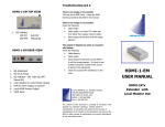
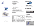
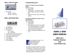
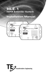
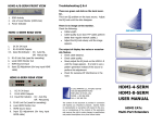
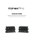
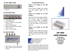
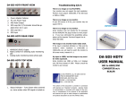
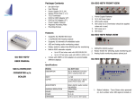
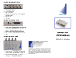
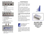
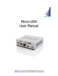
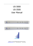
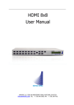
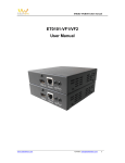
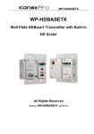
HDBT-1-E FRONT VIEW
Specifications
1.
2.
3.
4.
DC 12 V Input w/ Locking
LINK OUT (RJ45)
HDMI Input
RS232 Input
HDBT-1-E REAR VIEW
1.
2.
3.
4.
IR Output
HDCP Indicator
LINK Indicator
POWER Indicator
FEATURES/
MODEL
HDMI In
HDBT-1-E
HDBT-1-R
1 x HDMI AType Female
None
HDMI Out
1 x HDMI AType Female
1
RJ-45
1
IR OUT
IR IN
3.5 mm phone
jack
None
Max Resolution
1080p 60Hz
3.5 mm
phone jack
1080p 60Hz
Cable Distance
Power Adapter
100 meters
(Max)
12 V DC
100 meters
(Max)
12 V DC
Weight g)
310g
310g
Dimension
(mm)
None
150 W x 80 x 150 W x 80 x
D 25 H
D 25 H
HDBT-1-R FRONT VIEW
1.
2.
3.
4.
DC 12 V Input w/ Locking
LINK IN (RJ45)
HDMI Output
RS232 Output
© 2012 APANTAC LLC, All rights reserved
7556 SW BRIDGEPORT ROAD
PORTLAND, OR 97224, USA
PHONE +1 503 968 3000
FAX +1 503 389 7921
HDBT-1-R REAR VIEW
1.
2.
3.
4.
5.
IR Input
IR Input
HDCP Indicator
LINK Indicator
POWER Indicator
The content of this document is provided in connection
with Apantac LLC (“Apantac”) products.
Apantac
makes no representation or warranties with respect to
the accuracy or completeness of the contents of this
publication and reserves the right to make changes to
specifications and product descriptions at any time
without notice.
HDBT-SET-1
USER MANUAL
HDMI Extender/Receiver
based on
HDBaseT Technology
Package Contents
Installation
1 x HDBT-1-E
1 x HDBT-1-R
User Manual
2 x Power Adapters (12V)
1 x IR Blaster Cable
1 x IR Receiver Cable
Magnetic Mounting Plate
Mounting Screws
Accessories
1.
2.
3.
4.
5.
Turn off the source (ex: DVD Players) and the
HDTV monitor.
Connect the HDMI cable between the source and
the <HDMI IN> port of the HDBT-1-E.
Connect the HDMI cable between the HDBT-1-R
between the monitor and the <HDMI OUT> port
of the HDBT-1-R.
Connect the CATx cable between the HDBT-1-E
and HDBT-1-R’s <LINK> port.
Connect the power.
CATx Wiring
Identification
Pin
Assignment
Color Code
5
White-Blue
4
Blue
1
White-Orange
2
Orange
3
White-Green
6
Green
7
White-Brown
8
Brown
Pair 1
IR Receiver Cable
Insert the IR receiver cable into the HDBT-1-R’s
<IR2 IN> (so you can point to it easily with your
IR remote control).
Power Adapter
Pair 2
Pair 3
IR Receiver Cable
GND
+V
Si g
IR Blaster Cable
Mounting Screws
Features
Uses the latest HDBase-T technology
Extends 1080p signals up to 330 feet
(100 meters) with a single CATx cable
Supports HDMI 1.4 with 3D function
Supports HDMI 1.2 and 1.3a
HDCP Compliant
Supports 3D pass-through
Supports CEC pass-through
Supports RS-232 (Bi-directional transfer)
Supports al frequency band IR control
Pair 4
IR Blaster Cable
Insert IR blaster cable into HDMI-1-E <IR OUT>
port.
Locate it close to the IR receiving sensor on the
source (ex: DVD player).
NC
P+
N-
Pin
#
Signal
Pin
#
Signal
1
TMDS Data 2+
11 TMDS Clock Shield
2
TMDS Data 2 Shield
12 TMDS Clock -
3
TMDS Data 2-
13 CEC
4
TMDS Data 1+
14 (N.C. on device)
5
TMDS Data 1 Shield
15 SCL
6
TMDS Data 1-
16 SDA
7
TMDS Data 0+
17 DDC/CEC Ground
8
TMDS Data 0 Shield
18 +5 Power
9
TMDS Data 0-
19 Hot Plug Detect
10 TMDS Clock+
Reserved