Download User Manual


Transcript
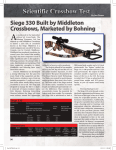
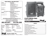
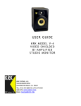
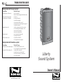
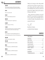
TROUBLESHOOTING GUIDE
Having trouble with the sound system?
Condition
Possible Cause
No sound (power LED not lit):
•
•
•
•
•
•
•
Charge indicator doesn’t light:
No sound (power LED lights):
Shortened battery life:
•
•
•
•
•
•
•
•
Distorted sound:
Excessive hum or noise:
power switch OFF
batteries fully discharged (LED flashes briefly)
blown fuse
no output from source
input cable unplugged
input volume control low or off
plug inserted into switched speaker output, but
no speaker connected
short in external speaker cable or speaker
total external speaker impedance < 4Ω
batteries not fully charged
batteries need replacement
poor connection on input cable
input signal too strong
input cable not shielded
not using balanced microphone
Having trouble with the wireless system?
Condition
Possible Cause
No sound (TX ON indicator lights):
•
•
•
•
•
•
No sound (TX ON indicator off):
wireless volume control low or off
no mic plugged into belt-pack transmitter
sound system not turned on
transmitter power switch turned off
low battery or no battery in transmitter
not on same channel
Liberty
Sound System
Owner’s Manual
ANCHOR Audio, Inc. (310) 784-2300
100-0134-000 / Revision A - 09/03
IMPORTANT SAFEGUARDS
SPECIFICATIONS
Liberty
Rated power output:
50 watts @ 4Ω continuous
Max SPL @ rated power:
WARNING: To prevent fire or electric shock, do not expose this equipment to rain or
moisture.
117 dB speech projection on
107 dB speech projection off
Batteries (two):
12 Volt rechargeable, 7.0 AH
CAUTION: To reduce the risk of fire, replace only with same type fuse (see specifications).
General
CAUTION: To reduce the risk of electric shock, do not remove the cover. No user-serviceable
parts inside. Refer servicing to qualified personnel.
ATTENTION: Pour eviter les risques de choc électrique, ne pas enlever le couvercle. Aucun
entretien de pièces intérieures par l'usager. Confier l'entretien au personnel qualifié.
AVIS: Pour eviter les risques d'incendie ou d’électrocution, n'exposez pas cet article à la
pluie ou a l'humidité.
ATTENTION: Pour diminuer le risque d’incendie, remplacer par des fusibles de même type
(voir caractéristiques).
EXPLANATION OF GRAPHICAL SYMBOLS
Frequency response:
60 Hz - 15 kHz ± 3 dB speech projection off
+ 10 dB from 1.5 - 12kHz speech projection on
Speaker type:
8" woofer, titanium dome compression driver
Inputs
Microphone inputs (two):
Lo-Z (1 kΩ), balanced, XLR
12 VDC / 6.8 k condenser mic power
Auxiliary (line) input:
Hi-Z (10 kΩ), unbalanced, 1⁄4"-phone
Sensitivity for rated output
The lightning flash with arrowhead symbol, within an equilateral triangle, is intended to
alert the user to the presence of uninsulated “dangerous voltage” within the product’s
enclosure that may be of sufficient magnitude to constitute a risk of electric shock to
humans.
Microphone:
-52 dBV (2.5 mVrms)
Auxiliary (line):
-14 dBV (200 mVrms)
The exclamation point, within an equilateral triangle, is intended to alert the user to the
presence of important operating and maintenance (servicing) instructions in the literature
accompanying the appliance.
Line output (post fader):
Lo-Z (< 1 kΩ), buffered, 1⁄4"-phone
Speaker out; switched:
8Ω, 1⁄4"-phone
Speaker out; unswitched:
4Ω, 1⁄4"-phone
DC Output:
12 Volts DC, 300 ma max.
AC power requirements:
Export model:
110-125 VAC, 50/60 Hz, 50 watts max
208-240 VAC, 50/60 Hz, 50 watts max
Dimensions (HWD):
22.5 x 13 x 10", 57 x 33 x 25 cm
Weight:
44 pounds, 20 Kg.
EXPLICATION DES SYMBOLES GRAPHIQUES
Le symbole éclair avec point de flèche à l'intérieur d'un triangle équilatéral est utilisé pour
alerter l'utilisateur de la presence à l'intérieur du coffret de “voltage dangereux” non isolé
d'ampleur suffisante pour constituer un risque d'elétrocution.
Le point d'exclamation à l'intérieur d'un triangle équilatéral est employé pour alerter les
utilisateurs de la présence d'instructions importantes pour la fonctionnement et l'entretien
(service) dans le livret d'instruction accompagnant l'appareil.
Outputs
DATE OF MANUFACTURE
The date of manufacture of this Anchor Audio product can be determined by the six digit
serial number code. The 1st digit denotes the month (A=Jan, B=Feb, etc.), the 2nd digit
denotes the year.
Specifications subject to change without notice.
Example: “H20142” states that the unit was manufactured in August of 2002.
13
ACCESSORIES
LIB-6001
Dual function (speech projection on/off) unpowered companion
speaker for the Liberty Sound System (Speaker cable not included)
SC-50
Heavy duty 50' speaker cable
SS-550
Heavy duty brushed aluminum speaker stand
MSB-201
Microphone floor stand with 33" adjustable boom
Thank you for choosing an Anchor Audio portable
sound system. Our products incorporate state-ofthe-art design and the finest quality of materials
and workmanship. We’re proud of our products and
appreciate the confidence which you have shown by
selecting an Anchor system.
I hope you’ll take a few of minutes to review this
manual. We’ve incorporated several unique features
into our products, and your knowledge of how to
use them will enhance the performance and your
enjoyment of the system.
NL-6000
Heady duty storage cover for Liberty
FL-4500
Admiral floor model lectern with a center console to accommodate a
Liberty sound system, includes a shock-mounted mic input
David Jacobs, President
on behalf of all Anchor Employees
MIC-90
Dynamic, balanced, low impedance handheld microphone with
unidirectional pick-up pattern, on/off switch, 20' cable and mic clip
WH-6000
Handheld wireless microphone/ transmitter
WB-6000
Wireless body-pack transmitter (order mic separately)
CONTENTS
Getting Started ………………………………………2
Precautions ……………………………………………3
System Setup ………………………………………4-5
Battery Operation ……………………………………6
General Operation …………………………………7-8
CM-60
CollarMic microphone (use with WB-6000 transmitter)
CD Player Operation …………………………………9
Wireless Operation ……………………………10-11
HBM-60
Accessories …………………………………………12
Headband microphone (use with WB-6000 transmitter)
Specifications ………………………………………13
LM-60
Troubleshooting Guide……………………back cover
Lapel microphone (use with WB-6000 transmitter)
12
1
GETTING STARTED
WIRELESS OPERATION
System Inspection & Inventory
Check unit carefully for damage which may have occurred during
transit. Each Anchor product is carefully inspected at the factory
and packed in a special carton for safe transport.
Inventory
NOTE:
All damage
claims must
be made with
the freight
carrier.
• Liberty sound system
• Warranty registration card
All damage claims must be made with the freight carrier. Notify the
freight carrier immediately if you observe any damage to the
shipping carton or product. Repack the unit in the carton and await
inspection by the carrier’s claim agent. Notify your dealer of the
pending freight claim.
Returning Systems For Service or Repair
IMPORTANT:
Save the
shipping
carton and
packing
materials.
They were
specially
designed to
ship your unit
safely.
Should your unit require service, contact your dealer or the Anchor
Audio Customer Service Department at (800) 262-4671 to obtain a
Return Authorization (RA) number. All shipments to Anchor Audio
must include an RA number and must be shipped prepaid. C.O.D.
shipments will be refused and returned at your cost.
Warranty Registration
Please fill out the warranty card and return it with a copy of your
invoice to Anchor’s Customer Service Department. This will
activate your limited six year warranty.
Wireless Microphone Operation
NOTE:
When using a
dual wireless
unit, make
sure each
microphone is
set to a
different
channel
frequency.
Both the receiver and microphone must be set to the same channel.
1. If you are using a body-pack transmitter, insert the plug from
the mic into the jack marked MIC on the transmitter.
2. Turn the transmitter power switch to ON.
(The red LED will flash when the mic is turned on.
If the red LED stays on, the battery is low.)
3. Turn the Liberty power switch to ON.
4. The RX indicators will light (one indicator at a time lights)
when the wireless signal is being transmitted and received.
Replacing Transmitter Battery
CAUTION:
Harmful
feedback may
occur when
walking in
front of a
sound system
or speaker
with a
wireless
microphone.
Always point
mic away
from speakers.
Handheld Transmitter:
1. Unscrew battery compartment cover on lower end of mic.
2. Install 2 fresh ‘AA’ alkaline batteries.
3. Replace the battery cover.
Place batteries into slot
and slide forward
Body-pack Transmitter:
1. Slide open battery cover on front of transmitter box.
2. Install 2 fresh ‘AA’ alkaline batteries.
3. Close the battery cover.
NOTE:
Transmitter
power switch
must be in the
OFF position
when
changing
batteries
2
11
WIRELESS OPERATION
PRECAUTIONS
Diversity Wireless by Anchor Audio
Feedback
Anchor Audio UHF wireless is a 16 channel, diversity wireless
system that utilizes two independent antennae to receive signal. The
diversity feature means that the receiver will process the stronger of
the two antenna signals, effectively minimizing dropouts and
interference from other transmitting sources. The antennae are
mounted internally so there are no obstructions or risk of damage.
Feedback is a howling or shrill sound that is self-generated by the
sound system. It is caused by microphone pickup of the sound
emanating from the speaker and then being re-amplified. Once
generated, this can be a self-sustaining phenomenon.
Feedback Causes
Receiver Channel Selection
NOTE:
If you
experience
ongoing
interference
with your
wireless
system, the
selected
frequency
may be
incompatible
with other RF
systems in
your area.
Try a different
channel.
Before you use your UHF wireless system, you will need to select a
wireless frequency channel. The wireless receiver is mounted inside
the Liberty and can be set to any of 16 available channels.
Transmitter Channel Selection
Handheld Transmitter:
1. Unscrew battery cover on lower end of microphone.
2. Set the channel selection
dial to match the channel
setting on the receiver.
Microphone too close, pointing towards or in
front of speaker.
•
Volume setting too loud for room.
•
Sound reflections from hard surfaces, walls, etc.
Avoiding & Eliminating Feedback
1. Locate the Wireless Channel
selector on the back panel.
2. Set the Channel (frequency)
of the receiver to 1 thru 16.
•
CAUTION:
Feedback can
be damaging
to both your
equipment
and a persons
hearing.
•
Point the microphone into a different direction.
•
Keep the microphone away from the speaker; position
the speaker in FRONT of the microphone.
•
Reduce the volume of the sound system. Have all
volume controls set to minimum prior to powering on
the sound system.
•
Place sound dampening material over hard surfaces;
curtains or sound dampening foam.
3. Replace the battery cover.
Body-pack Transmitter:
NOTE:
Be sure that
the MIC/LINE
switch is in
the “MIC”
position when
a mic is
plugged into
the body-pack
transmitter.
10
1. The channel selection dial
is located on the side of
the transmitter.
2. Set the channel selection
dial to match the channel
setting on the receiver.
Acceptable
Unacceptable
3
SYSTEM SETUP
CD OPERATION
Setting Up The Liberty Sound System
For best results, it is recommended that the PA system be placed
above the heads of the audience and above the height of the tallest
obstruction using a speaker stand or table. This will benefit the
listeners in the rear while minimizing the risk of overpowering the
listeners in front.
CAUTION:
To avoid
noise at shut
off, turn CD
player off
before you
turn off the
Liberty.
CD Slot
LCD Display
Power On/Off
General Operation
Stand Setup
1. Loosen the Lower Collar Knob.
Upper Collar
Knob
2. Separate the stand legs until the
leg support cross braces are
parallel to the floor.
INSERT CD - Push a disc into the CD slot label side up. The disc
will automatically insert and begin to play.
POWER ON/OFF - Press POWER to turn the unit on and off.
Lower Collar
Knob
3. Tighten the Lower Collar Knob.
4. Extend the center pole by
loosening the Upper Collar Knob.
5. Adjust the height and retighten
the Upper Collar Knob.
6. Place the Anchor sound system
on the stand.
The CD player features direct-in play power loading, anti-shock/skip
CD mechanism, repeat & random play, three beam laser tracking
system and dual one bit D/A converters. The audio signal is fed
directly into the mixing bus, mixing it directly with all other inputs
of the Liberty for a composite output.
Cross Braces
Sound System Placement
The ideal placement of the sound system is between the crowd and
the presenter, facing the crowd. This will give the audience a direct
signal path and keep the person with the microphone behind the
sound system, helping to prevent feedback from occurring.
Single Unit Application
Place the unit along the aisle with the least amount of pedestrian
traffic. Point the unit towards the center of the audience.
EJECT CD - Press EJECT to eject the disc from the slot. If the disc
has not been removed within 10 seconds, it will automatically be
loaded into the slot again.
PLAY/PAUSE - Press to play a disc if one has been loaded. Press
this button while disk is playing to pause play, press again to resume.
UP - Press UP once to advance disc to next track. Press and hold
UP to fast forward on the current track.
DOWN - Press DOWN once to go to previous track. Press and hold
DOWN to fast backward on current track.
TOP - Press TOP once to start playing the disc from the first track.
RANDOM - Press RDM to play all the tracks continuously in
random order. Press RDM again to stop continuos random play.
REPEAT - Press this button to repeat the same track of the disc
continuously. RPT Will appear on the display, press again to stop it.
4
9
GENERAL OPERATION
SYSTEM SETUP
Mic 1 and Mic 2
Two Unit Application
These balanced XLR, low impedance inputs are for use with
balanced microphones to help prevent hum or interference when
using long cables. They feature +12VDC condenser mic power for
use with condenser-type microphones.
Place each unit along the aisles pointing just off the centerline of the
audience. With the sound system placed properly over the head of
the crowd, this should be sufficient coverage.
10
Speech Projection on (button in):
Frequencies in the vocal range (800Hz-12kHz) are boosted for added
clarity and efficient sound projection. Use this setting for outdoor
functions, large crowds and speech applications.
8
20
The Liberty provides flat, full-range frequency response for music or
indoor voice applications.
30
Speech Projection off (button out):
40
The Speech Projection switch allows you to customize the sound
output of the Liberty for a particular application:
50
Speech Projection
40
The DC output jack is used to power auxiliary equipment such as an
outboard wireless receiver or Anchor Audio’s Mini-Mix. It is rated
at 12 volts DC, 300 milliamps maximum (output available at jack
may be slightly lower depending on installed options).
30
10
LIB-6001
20
30
40
50
40
LIB-6000
30
20
LIB-6000
10
LIB-6001
LIB-6000
LIB-6000
High School Football Stadium/Stands
Line Out
12 Volt DC Output
20
LIB-6001
The unbalanced, high impedance, input is used for playback of a
cassette or CD player, musical instrument, VCR, other sound system
or similar line-level signal source. This input may be used in
conjunction with other inputs for a composite output.
The unbalanced Line-out provides a combined signal of all inputs
being used. You can use this function to record your presentation or
to “daisy chain” another powered sound system to the Liberty for
greater crowd coverage. Note: This output is post source level; any
volume fluctuations for a specific input will affect the output signal
level at this output.
10
Line In
Auditorium / Outdoor Assembly/City Hall
Sound System Connection
NOTE:
Auditoriums
or outside
areas with
large exposed
walls or
patios may
create multiple
reflections of
the original
sound.
Altering the
sound system
position will
minimize the
sound
reflections.
There are two ways of connecting two or more Liberty sound
systems together. The simplest method would be to use the speaker
output of the primary unit and connect it to the unpowered
companion speaker using an SC-50 speaker cable. No electric
power is required for an unpowered companion speaker.
The second method would be to utilize the line-output feature.
Simply connect a (EX-50PP) cable from the line-out of the primary
Liberty to the line-in on the secondary powered Liberty. Set the
volume of the second Liberty to maximum so that full volume
control will be at the primary sound system.
Secondary
Powered
Liberty
System
LIB-6000HC
LIB-6000HC
Primary
Powered
Liberty
System
Line Out - to - Line In Connection
The line-out connection can also be used to send the signal to a
sound system in a different room or a recording device.
5
BATTERY OPERATION
GENERAL OPERATION
Caring For Built-in Batteries
It is very important that you fully charge the batteries in your system
before first use and as soon as possible after each and every use,
even if operated only briefly to preserve battery life.
When The Battery LED Flashes or Won’t Light
The Battery LED will begin to flash when the battery charge is low.
To prevent damage, the automatic protection circuit turns the unit off
when the batteries approach their critical discharge point; about 1530 minutes.
Charging Batteries
Your system has a built-in automatic charger designed to properly
charge and maintain the batteries. The following steps outline the
necessary procedure to charge the batteries:
Liberty Control Panel
NOTE:
Instructions
for wireless
operation can
be found on
pages 10 & 11.
1. Set all input level controls to minimum and tones controls to
flat or middle position before turning on the power.
2. Plug a microphone into Mic 1 or Mic 2, or plug an audio
source into the Line-in input jack.
3. Press POWER on. The red LED near the switch will light.
4. Slowly increase the level control adjacent to the input jack
used to desired volume.
5. For speech applications, Speech Projection should be “on” to
overcome ambient noise. For standard applications (music
and indoors), Speech Projection should be “off”.
6. Adjust Bass and Treble controls for desired sound quality.
Wireless Receiver Controls
IMPORTANT:
Always store
your system
with the
batteries in a
fully charged
condition.
During
extended
periods of
storage, leave
the system
plugged into
an outlet. If
this is not
possible,
charge the
system at
least once
each month
for a
minimum of
24 hours.
6
CD Player
1. With the power switch off, plug the cord into an AC outlet.
The Charger LED will light, indicating the batteries are
being charged.
2. When the batteries are fully charged (about 6-8 hours), the
Charger LED will flash.
CD Volume
Input Level
Controls
Expected Battery Service Time
Tone Controls
Battery service time will vary depending on the volume level, tone
control settings, type of program usage and if a companion speaker
is used with the system. You can expect about 6-8 hours of
operation at medium volume, 2-4 hours at full volume of continuous
music input (usually longer for speech applications).
Speech/
Projection
Switch
Line Out
Input Jacks
Charger
Indicator
DC Output
Speaker
Outputs
(Switched)
Speaker
Outputs
(Unswitched)
Battery Level
Indicator
Fuse
Power Switch
LIB-6000HCU2
Back Panel
AC Inlet
7