1
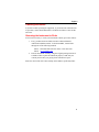
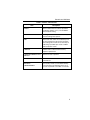
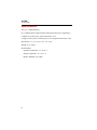
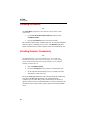
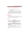
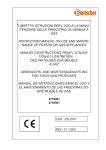
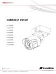
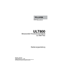
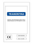
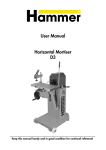
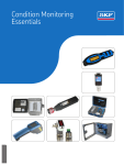
ULT800
TEE Transducer Leakage Current Tester
Users Guide
PN 2461434
August 2005
© 2005 Fluke Corporation, All rights reserved. Printed in USA
All product names are trademarks of their respective companies.
Warranty and Product Support
Fluke Biomedical warrants this instrument against defects in materials and
workmanship for one full year from the date of original purchase. During the
warranty period, we will repair or, at our option, replace at no charge a product that proves to be defective, provided you return the product, shipping
prepaid, to Fluke Biomedical. This warranty does not apply if the product has
been damaged by accident or misuse or as the result of service or modification
by other than Fluke Biomedical. IN NO EVENT SHALL FLUKE BIOMEDICAL BE LIABLE FOR CONSEQUENTIAL DAMAGES.
Only serialized products and their accessory items (those products and items
bearing a distinct serial number tag) are covered under this one–year warranty.
PHYSICAL DAMAGE CAUSED BY MISUSE OR PHYSICAL ABUSE IS
NOT COVERED UNDER THE WARRANTY. Items such as cables and
nonserialized modules are not covered under this warranty.
Recalibration of instruments is not covered under the warranty.
This warranty gives you specific legal rights, and you may also have other
rights which vary from state to state, province to province, or country to
country. This warranty is limited to repairing the instrument to Fluke Biomedical’s specifications.
Warranty Disclaimer
Should you elect to have your instrument serviced and/or calibrated by someone other than Fluke Biomedical, please be advised that the original warranty
covering your product becomes void when the tamper-resistant Quality Seal is
removed or broken without proper factory authorization. We strongly recommend, therefore, that you send your instrument to Fluke Biomedical for
factory service and calibration, especially during the original warranty period.
In all cases, breaking the tamper-resistant Quality Seal should be avoided at all
cost, as this seal is the key to your original instrument warranty. In the event
that the seal must be broken to gain internal access to the instrument, you
must first contact Fluke Biomedical’s Technical Assistance Department at
775-883-3400. You will be required to provide the serial number for your instrument as well as a valid reason for breaking the Quality Seal. You should
break this seal only after you have received factory authorization. Do not
break the Quality Seal before you have contacted us. Following these steps
will help ensure that you will retain the original warranty on your instrument
without interruption.
Fluke Biomedical, 6920 Seaway Blvd., Everett, WA 98203 USA
Introduction
The ULT800 TEE Transducer Leakage Current Tester measures the
leakage current of ultrasound transducers independent of their ultrasound
systems. Use the hand-held, battery-operated instrument during the routine
transducer cleaning procedure conducted between patients.
Connect the transducer to be tested to the ULT800 via a unique adapter.
The ULT800 performs the measurement with the transducer immersed in
either the cleaning solution or saline. To insure that the leakage current
test is accurate, first test the conductivity of the fluid. A special dual
element probe also connected to the ULT800 tests the conductivity of the
fluid. A green PASS light or a red FAIL light indicates the results of the
conductivity and leakage current tests.
In addition to verifying that the ultrasound transducers are safe for patient
use, the ULT800 makes it possible to reduce expensive repairs. Identifying
transducers that exceed safe leakage currents early may allow for repairs
to be made before a transducer becomes non-repairable.
Key Features
•
Hand-held instrument
•
Stand-alone operation
•
Direct measurement of leakage current
•
Battery operation for safety
•
Independent of 120 or 240V ac systems
•
Built-in self-test circuit
•
Auto shut off to conserve battery
1
ULT800
Users Guide
Support
Customer Support and Sales
USA and Canada:
Outside the USA:
E-Mail: sales@flukebiomedical.com
Internet: www.flukebiomedical.com
800.648.7952
775.883.3400
Service
Service:
Outside the USA:
E-Mail:
888.993.5853
425.446.5560
service@fluke.com
For additional sales or service information, contact your local Fluke
Biomedical Distributor or Fluke Electronics office.
Claims
Our routine method of shipment is via common carrier, FOB origin. Upon
delivery, if physical damage is found, retain all packing materials in their
original condition and contact the carrier immediately to file a claim.
If the instrument is delivered in good physical condition but does not operate
within specifications, or if there are any other problems not caused by shipping
damage, please contact Fluke Biomedical or your local sales representative.
Certification
This instrument was thoroughly tested and inspected. It was found to meet
Fluke Biomedical’s manufacturing specifications when it was shipped from the
factory. Calibration measurements are traceable to the National Institute of
Standards and Technology (NIST). Devices for which there are no NIST
calibration standards are measured against in-house performance standards
using accepted test procedures.
2
Support
Obtaining Assistance
If you have trouble operating the equipment, or just need some clarification on
its operation, contact Fluke Biomedical’s Technical Assistance Center at 800648-7952.
Returning the Instrument to Fluke
If it becomes necessary to return your instrument to Fluke, proceed as follows:
1.
Every product returned to Fluke must have a Return Material
Authorization (RMA) number. To obtain an RMA, contact Fluke
through one of the following methods:
Phone: 888-99FLUKE (888-993-5853) or 425-446-5560
Email: service@fluke.com
2.
Pack the instrument carefully, using the original packing materials if
available. Failure to pack the instrument properly could void your
warranty and result in you paying for the instrument’s repair.
Insure the unit for full retail value and ship to the address specified by Fluke.
3
ULT800
Users Guide
Controls and Indicators
Input connectors are interchangeable and provide for inputting an
ultrasound transducer adapter and the dual conductivity electrode. Refer to
Figure 1 and Table 1 for complete control and indicator descriptions.
ULT800
Biomed
ical
TEE TR
LEAKAGANSDUCER
E CURR
ENT TEST
ER
READY
LEAKAG
PASS
FAIL
LOW BAT
E
ON
CONDU
CTIVITY
TEST
INSTRU
CTIONS
1. Conn
:
ect the
transdu
cer and
2. Pres
the adap
s the ON
ters to
/TEST bu
the ULT
tton an
3. Select
800.
d wait fo
CONDUC
r the RE
Wait fo
TIVITY
ADY lig
r the PA
an
d press
ht.
SS light
th
e
.
ON
4. Select
/TEST Bu
LEAKAG
ttonE and pr
observ
e PASS
ess the
or FAIL
ON/TES
TRANSD
light. If
T butto
UCER.
test fails
n againRefer to
, DO
the user
’s manua NOT USE
l.
ecy10f.eps
Figure 1. Controls and Indicators
4
Controls and Indicators
Table 1. Controls and Indicators
Item
Description
READY
Glows amber when the self-test procedure
completes (approx. 8 sec.). The ULT800 is
then ready for testing.
PASS
Glows green when either the Conductivity
Test or Leakage Test passes.
FAIL
Glows red when either the Conductivity Test
or the Leakage Test fails. Pulses red when
the Leakage Test results in less than 20 µA,
indicating a possible open circuit condition
with invalid test results.
LOW BAT
Flashes red to indicate that the battery
requires replacement.
LEAKAGE/CONDUCTIVITY
SWITCH
Selects the test to perform.
ON/TEST BUTTON
Turns the ULT800 on and initiates the
selected test.
BATTERY
COMPARTMENT
(not shown): Holds a 9-volt alkaline battery.
The instrument automatically powers off if
you do not perform a test within 12 seconds.
5
ULT800
Users Guide
Specifications
Power: 9 V Alkaline Battery
No. of Measurements: Approximately 1000 measurements on a single battery
Conductivity: Limit to pass: greater than 250 µA ±5 %
Leakage: Limits to pass: less than 100 µA ±5 % and greater than 20 µA ±5 µA
Dimensions: 6.5 x 3.7 x 1.5 in. (17 x 19 x 4 cm)
Weight: 12 oz (340 g)
Environmental
Operation Temperature: 15 ° to 40 ° C
Storage Temperature: 15 ° to 65 ° C
Relative Humidity: 90 % Max
6
Using the ULT800
Using the ULT800
X W Warning
To avoid personal injury, do not touch the dual
conductivity electrode rods. Voltage is present on the rods
during a test.
Inspect the conductivity probe for damaged insulation or
exposed metal. To avoid personal injury, replace a
damaged conductivity probe before using.
W Caution
To avoid damage to the transducer, observe the immersion
levels. Do not immerse or allow the cable or connector of a
transducer to become wet.
The ULT800 TEE Transducer Leakage Current Tester is a portable, selfcontained, battery-operated device. It measures the leakage current of the
devices attached to its connectors. The ULT800 applies 120 VAC, 60 Hz
to devices placed in a conductive bath (basin or storage tube). The
ULT800 measures the current and compares the results to an internal
threshold. The instrument displays the results as a PASS or FAIL
indication. It also performs an internal self-calibration on each
measurement cycle.
The ULT800 makes two types of measurements. The Leakage Test
measures the current between the probe and the electrode. The
Conductivity Test measures the conductivity of the bath solution between
the two electrodes.
Figures 2 and 3 show some typical test setups. Figure 2 shows the
HP/Agilent Disinfection Basin (HP Part No. 21110A). Figure 3 shows the
ATL Disinfection and Storage Tube. You can use other setups, as long as
you observe the following rules:
1.
Connect the ultrasound probe you are testing to the probe
adapter. See the list of available adapters under Accessories.
2.
Place the probe you are testing in a saline bath with the entire
critical area of the probe fully immersed.
3.
Place the dual electrode (Part No. 2392502 or 2392569) in the
saline bath to a depth of at least one inch.
7
ULT800
Users Guide
4.
Plug the probe adapter and the electrode wire connectors into the
ULT800. The connections are fully interchangeable.
600/212
X
HP/Agilent
ULT800
TEE TRANSDUCER
LEAKAGE CURRENT TESTER
Biomedical
READY
PASS
FAIL
LOW BAT
LEAKAGE
ON
CONDUCTIVITY
Fluke
ULT800
600/210
TEST
INSTRUCTIONS:
1. Connect the transducer and the adapters to the ULT 800.
2. Press the ON/TEST button and wait for the READY light.
3. Select CONDUCTIVITY and press the ON/TEST ButtonWait for the PASS light.
4. Select LEAKAGE and press the ON/TEST button againobserve PASS or FAIL light. If test fails, DO NOT USE
TRANSDUCER. Refer to the user’s manual.
ecy02f.eps
Figure 2. HP/Agilent Disinfection Basin Test Setup
8
Using the ULT800
600/210
HP/Agilent
Transducer Adapter
Fluke
ULT800
X
ULT800
TEE TRANSDUCER
LEAKAGE CURRENT TESTER
Biomedical
READY
PASS
FAIL
LOW BAT
LEAKAGE
ON
CONDUCTIVITY
TEST
INSTRUCTIONS:
1. Connect the transducer and the adapters to the ULT 800.
2. Press the ON/TEST button and wait for the READY light.
3. Select CONDUCTIVITY and press the ON/TEST ButtonWait for the PASS light.
4. Select LEAKAGE and press the ON/TEST button againobserve PASS or FAIL light. If test fails, DO NOT USE
TRANSDUCER. Refer to the user’s manual.
600/212 Dual
Conductivity
Electrode
with 600/213
Extenders
ATL
Disinfection
and Storage
Tube
ecy03f.eps
Figure 3. ATL Disinfection/Storage Tube Setup
9
ULT800
Users Guide
Checking the Battery
Note
The LOW BAT light flashes red to indicate that the battery needs
replacement.
1.
Use the LEAKAGE/CONDUCTIVITY switch to select
CONDUCTIVITY.
2.
Press the ON/TEST button to turn on the ULT800.
The self-check routine starts, calibrating the unit. All four LED indicators
flash in sequence, continuing for five cycles. The READY light glows
amber when the self-test routine completes with a successful battery test.
Checking Solution Conductivity
Note
The LED indicating a test result remains on for 12 seconds. The
ULT800 then powers off to conserve the battery. To resume testing,
power on the ULT800, allow the self-check/battery test to complete,
and then reinitiate the test.
1.
Select CONDUCTIVITY.
2.
Press the ON/TEST button to perform a measurement cycle.
3.
At the end of the measurement cycle (two seconds), the LED
indicates the results of the test.
The green PASS light illuminates if the solution passed the Conductivity
Test. The red FAIL light illuminates if the solution failed the
Conductivity Test. Check that you have immersed the electrodes to a
depth of at least 25 mm (1 inch) and that they are firmly connected to the
ULT800, then retest. If the failure repeats, replace the solution and then
retest.
10
Testing for Transducer Leakage Current
Testing for Transducer Leakage Current
Note
Perform the Leakage Test only if the Conductivity Test passes.
1.
Select LEAKAGE.
2.
Press the ON/TEST button to perform a leakage measurement.
The green PASS light illuminates if the transducer passed the leakage
current test. The red FAIL light illuminates if the transducer failed the
leakage current test. If there is less than 20 µA of leakage current, the red
light pulses, indicating a possible open circuit condition with invalid test
results.
Maintenance
Your ULT800 needs little maintenance or special care. However, treat it
as a calibrated measuring instrument. Avoid dropping or other mechanical
abuse that could cause a shift in the calibrated settings.
Cleaning
W Caution
Do not pour fluid onto the ULT800 surface; fluid seepage
into the electrical circuitry may cause ULT800 failure.
W Caution
Do not use spray cleaners on the ULT800; such action may
force cleaning fluid into the ULT800 and damage electronic
components.
Clean the ULT800 occasionally utilizing a damp cloth and mild detergent.
Take care to prevent the entrance of liquids.
Wipe down the adapter cables with the same care. Inspect them for
damage to and deterioration of the insulation. Check the connections for
integrity.
11
ULT800
Users Guide
Battery
W Warning
The 9-volt alkaline battery provided with the ULT800 may
explode or leak if recharged, inserted improperly, disposed
of in a fire, or mixed with different battery types. Dispose
of the battery in accordance with any applicable state or
local regulations.
The ULT800 uses a standard 9-volt alkaline battery. The battery has a life
expectancy of approximately 1000 measurements. Replace the battery
yearly, regardless of its condition.
Calibration
W Warning
Examine the calibration label on the back of the ULT800
prior to each use. Do not use a ULT800 with an expired
calibration label. A ULT800 without a calibration label or
with the anti-tamper case label broken is out of calibration.
A ULT800 that is out of calibration can cause excessive
leakage current exposure to the patient; risk of injury to
the patient could result.
W Caution
Avoid dropping the ULT800 or allowing other mechanical
abuse that could cause a shift in the ULT800’s calibrated
settings.
The ULT800 requires yearly Fluke factory calibration, which uses
appropriate tools and reference instruments that are traceable to the
National Institute of Standards and Technology (NIST). Factory
calibration provides a calibration sticker on the back of the ULT800 to
verify that the calibration was performed.
To locate a service center, visit the Fluke web site at www.fluke.com, or
contact Fluke at service@fluke.com. Call from anywhere in the world at
+1-425-446-5500 or call for service in the USA at 1-888-99-FLUKE (1888-993-5853.)
12
Accessories
Accessories
Refer to Table 2 for a list of transducer adapters and other accessories for
the ULT800.
Table 2. Accessories
Part
Number
Model
Number
Description
2392430
600/156FG
Ultrasound Transducer Adapter –
Siemens/Acuson 156 series probes
2392453
600/202FG
Ultrasound Transducer Adapter – GE
YMS/RT
2392466
600/203FG
Ultrasound Transducer Adapter – GE
CGR
2392475
600/204FG
Ultrasound Transducer Adapter – GE
LogiQ
2231602
600/205
Ultrasound Transducer Adapter – GE
LogiQ
2392482
600/210FG
Ultrasound Transducer Adapter –
HP/Agilent
2392494
600/211FG
Ultrasound Transducer Adapter –
HP/Agilent
2392516
600/213FG
Ultrasound Transducer Adapter –
Acuson/Toshiba
13
ULT800
Users Guide
Table 2. Accessories (cont.)
Part
Number
Model
Number
Description
2392540
600/216FG
Ultrasound Transducer Adapter – Hitachi
2392557
600/218FG
Ultrasound Transducer Adapter –
Philips/ATL
2392578
600/260FG
Ultrasound Transducer Adapter –
Siemens/Acuson 260 series probes
2231811
600/360
Ultrasound Transducer Adapter –
Siemens/Acuson 360 series probes
2392591
600/MPFG
Ultrasound Transducer Adapter –
Siemens/Acuson MP series probes
2392427
600/102FG
Chassis ground probe, 8-foot coiled cord
2231616
600/206
Universal ultrasound probe
2392502
600/212FG
Dual conductivity electrode
2392525
600/214FG
Hard-sided carrying case
2392533
600/215FG
Conductivity cable
2392569
600/220FG
Dual conductivity probe
14
Symbols
Symbols
Symbol
Description
W
See Users Guide
X
Caution: risk of electric shock
Standby – On
Manufacturer’s declaration of product compliance
with applicable EU directives
P
>
UL Listing mark
LISTED
58GB
E233218
~
6AM-6P1
Do not mix with solid waste stream. Dispose using a
qualified recycler or hazardous material handler.
9V
c
9-volt battery
15
ULT800
Users Guide
16