1
UNIVERSITI TEKNOLOGI MALAYSIA
DECLARATION OF THESIS / UNDERGRADUATE PROJECT PAPER AND COPYRIGHT
Author’s full name :
HAWA DIYANA SAIM
Date of birth
:
15TH MAY 1985
Title
:
WIRELESS MESH ROUTING FOR TELEMEDICINE SYSTEM
Academic Session:
2007/2008
I declare that this thesis is classified as :
√
CONFIDENTIAL
(Contains confidential information under the Official Secret
Act 1972)*
RESTRICTED
(Contains restricted information as specified by the
organisation where research was done)*
OPEN ACCESS
I agree that my thesis to be published as online open access
(full text)
I acknowledged that Universiti Teknologi Malaysia reserves the right as follows :
1. The thesis is the property of Universiti Teknologi Malaysia.
2. The Library of Universiti Teknologi Malaysia has the right to make copies for the purpose
of research only.
3. The Library has the right to make copies of the thesis for academic exchange.
Certified by :
SIGNATURE
850515-14-6414
(NEW IC NO. /PASSPORT NO.)
Date : 12TH MAY 2008
NOTES :
*
SIGNATURE OF SUPERVISOR
DR. EKO SUPRIYANTO
NAME OF SUPERVISOR
Date : 12TH MAY 2008
If the thesis is CONFIDENTIAL or RESTRICTED, please attach with the letter from
the organisation with period and reasons for confidentiality or restriction.
“I hereby declare that I have read this thesis and in
my opinion this thesis is sufficient in terms of scope and
quality for the purpose of awarding a Bachelor’s Degree of
Electrical Engineering (Electronic).”
Signature: ………………………………
Name of Supervisor: Dr. Eko Supriyanto
Date: …………………………………
WIRELESS MESH ROUTING
FOR TELEMEDICINE SYSTEM
HAWA DIYANA BINTI SAIM
Submitted to the Faculty of Electrical Engineering
in partial fulfillment of the requirement for the degree of
Bachelor in Electrical Engineering (Electronics)
Faculty of Electrical Engineering
Universiti Teknologi Malaysia
MAY 2008
ii
“I hereby declare that this work as the product of my own effort with the
exception of excerpts cited from other works of which the sources were duly
noted.”
Signature: …………………………
Author’s Name: Hawa Diyana Saim
Date: ………………………………
iii
ACKNOWLEDGEMENT
First of all, I would like to express my gratitude to my supervisor, Dr.
Eko Supriyanto for all the guidance he has given me throughout the whole
project.
My family’s support and assistance are truly appreciated because without
them, I might have not made it this far. Thank you so much.
Not forgetting my friends who were with me through the ups and downs
of this whole project. I hope I helped you as much as you helped me.
iv
ABSTRACT
In rural areas the penetration of telecommunication services, for example
telephony and internet access, is low and in some regions non-existent. The
telecommunication operators consider rural area as uneconomical due to the
nature of these regions - remote, often inaccessible, lacking in infrastructure,
sparsely populated, low income households and people with low skills levels.
Therefore, it is very difficult to monitor the inhabitants of these rural areas
especially if they are suffering from medical conditions. By using the Linksys
WRT54GL router which works in the 2.4 GHz frequency band and with wireless
mesh routing programmed into the router, patients can be monitored at all times,
regardless of their distance from the health centers. The patient’s health data can
be monitored with a physiological monitoring system that has been tested to
work the wireless mesh router designed. It is basically about overcoming
distance and improving access to healthcare.
v
ABSTRAK
Di kawasan pedalaman, penerobosan servis telekomunikasi seperti
telefon dan internet adalah kurang memuaskan dan di setengah kawasan, tiada
langsung. Operator telekomunikasi melihat kawasan pedalaman sebagai kawasan
yang kurang menguntungkan oleh sebab-sebab seperti ia terpencil, sukar untuk
didatangi, kurang infrastruktur, kurang penduduk, pendatapan keluarga yang
rendah serta penduduk yang kurang mempunyai kemahiran. Oleh itu, ia adalah
sangat sukar untuk mengawasi penduduk-penduduk di kawasan pedalaman ini
jika mereka meghidap penyakit. Dengan menggunakan router Linksys
WRT54GL yang berfungsi pada jalur frekuensi 2.4 GHz dan befungsi dengan
protokol “mesh”, pesakit boleh sentiasa diawasi walaupun mereka jauh dari
pusat kesihatan atau hospital. Data pesakit boleh dilihat oleh doktor dengan
mengunakan satu sistem pengawasan fisiologi yang telah diuji dengan router ini.
Ini adalah satu tindakan untuk mengatasi jarak jauh serta memperbaiki sistem
kesihatan.
vi
TABLE OF CONTENTS
CHAPTER
1
2
TITLE
PAGE
DECLARATION OF THESIS
i
ACKNOWLEDGEMENT
ii
ABSTRACT
iv
ABSTRAK
v
TABLE OF CONTENTS
vi
LIST OF TABLES
viii
LIST OF FIGURES
ix
LIST OF ABBREVIATIONS
xi
LIST OF APPENDICES
xiii
INTRODUCTION
1.1 Background
1
1.2 Objective of Project
2
1.3 Scope of Project
3
1.4 Outline of Thesis
3
LITERATURE REVIEW
2.1 Introduction
4
2.1.1 Star Topology
6
2.1.2 Mesh Topology
7
2.1.3 Star-Mesh Topology
9
2.2 Applications of Wireless Networks in Health and
10
Medicine
2.3 Applications of Wireless Mesh Networks
2.3.1 Athens Wireless Network
11
12
vii
2.3.2 Berlin FreiFunk.net
3
4
5
13
2.4 Other Wireless Mesh Router/Modules
13
2.4.1 Crossbow’s MPR 2400 (MICAz)
13
2.4.2 Cirronet’s Wireless Mesh Modules
15
METHODOLOGY
3.0 Introduction
16
3.1 The Linksys WRT54GL
16
3.2 Work Flow and Work Breakdown
19
3.3 Gantt Chart
20
3.4 Design and Implementation
22
3.4.1 Mesh Routing
22
3.4.2 Shortest Path Algorithm
24
3.4.3 Implementing the Algorithm Using PuTTY
28
3.4.4 Main System Settings
31
RESULTS AND DISCUSSION
4.1 Router Configurations
32
4.2 Testing and Integration with Other System
34
CONCLUSION AND RECCOMENDATION
5.1 Conclusion
38
5.2 Recommendation
38
REFERENCES
40
APPENDICES
41
viii
LIST OF TABLES
TABLE
TITLE
PAGE
3.0
Specifications of the Linksys WRT54GL
18
3.1
Gantt Chart for PSM1
20
3.2
Gantt Chart for PSM2
21
ix
LIST OF FIGURES
FIGURE
TITLE
PAGE
1.0
Scope of Project
3
2.0
Network Cabling is Expensive & Difficult
6
2.1
Star Topology
6
2.2
Mesh Topology
8
2.3
Mesh Networks are Reliable
8
2.4
Installation is a Breeze
9
2.5
Star-Mesh Topology
9
2.6
A Body Sensor
11
2.7
A map of the active nodes in the Athens Wireless Mesh
12
Network
2.8
A partial map of the Berlin wireless mesh network
13
2.9
The MPR 2400 and its Block Diagram
14
2.10
The miniMESH DM1800, miniMESH 1810 and
15
VersaMESH DM2200
3.0
The Linksys WRT54GL (front)
17
3.1
The rear of the Linksys WRT54GL
18
3.2
The Block Diagram of the WRT54GL
19
3.3
Breakdown of Work Done for the Project
19
3.4
MPR Selection
23
3.5
MPR Forwarding (a) Normal Flooding (b) MPR
24
Flooding
3.6
Flowchart of Shortest Path Algorithm
26
3.7
The PuTTY Window
29
3.8
Password Prompt
30
x
3.9
/etc file directory
31
4.0
A Part of the Configuration File of the Router
34
4.1
A Pinging of another Laptop in the Network
35
4.2
A Successful Pinging of the Router
36
4.3
Integration with Physiological Monitoring System
36
4.4
Network Activity
37
xi
LIST OF ABBREVIATIONS
AES
Advanced Encryption Standard
BSSID
Basic Service Set Identifier
CD
Compact Disc
CTS
Clear To Send
DHCP
Dynamic Host Configuration Protocol
DSL
Digital Subscriber Line
ESSID
Extended Service Set Identifier
IEEE
Institute of Electrical and Electronic Engineer
IP
Internet Protocol
LAN
Local Area Network
MAC
Media Access Control
MPR
Multi Point Relay
OLSR
Optimized Link State Protocol
OQPSK
Offset Quadrature Phase Shift Keying
PAN
Personal Area Network
PC
Personal Computer
PDA
Personal Digital Assistant
QoS
Quality of Service
RF
Radio Frequency
RTS
Request To Send
SPI
Stateful Packet Inspection
SSH
Secure Shell
TKIP
Temporal Key Integrity Protocol
VPN
Virtual Private Network
WEP
Wired Equivalent Privacy
W-iFi
IEEE 802.11 Wireless Standards. Trademark of the Wi-Fi
xii
Alliance
WLAN
Wireless Local Area Network
WPA
WiFi Protected Access
WSN
Wireless Sensor Network
ZigBee
IEEE 802.15.4 Standard for Wireless Personal Area Network
xiii
LIST OF APPENDICES
APPENDIX
A
TITLE
The Configuration File for the OLSR Mesh
PAGE
41
Protocol
B
The UDHCPD Configuration File
43
CHAPTER 1
INTRODUCTION
1.1
Background
Telemedicine is a rapidly developing field. It is the application of
clinical medicine where medical information is transferred via telephone, the
internet or other networks. It is most beneficial for populations living in isolated
regions and is currently being applied in all medical domains.
In a traditional network, routers are used to direct data traffic from one
place, or node, to another. Each router has a specific set of locations from which
it can accept data, and a specific set of locations to which it can send data. A
mesh, or multi-hop network, is a highly decentralized way of organizing nodes
that does not require predetermined paths between them. Such networks are
made possible by mesh routers, which adjust, in real time, the locations with
which they can communicate.
Mesh routers work by continuously monitoring network activity and
maintaining lists of other devices in their vicinity. When a potential node
appears, it broadcasts its address and networking capabilities. Nearby mesh
routers will receive the broadcast, and adjust their own lists to reflect the new
node. When the device turns off or otherwise disappears, the mesh routers will
again update their lists.
If a known device broadcasts a request to send data to a specific location, and a
router has the receiving node on its list of active devices, it will complete the
path and transmit the data. If no individual mesh router can provide a direct path
2
between transmitting and receiving nodes, the data will be sent to another router
in the network, and the process repeated until a path can be found.
Because mesh routers are continuously adjusting to their environment,
the network they create is very robust and highly fault tolerant. With a large
enough mesh, it is possible to route around any failed or disappeared router; no
mesh router can be a point of failure for the entire network. The drawback of
such networks is that without predetermined routing paths, data may take a
longer time to reach its destination.
Mesh networks are often wireless devices. A mesh router can be as
simple as a wireless laptop set to operate in ad hoc mode. In this mode, the
laptop acts as the router. There are also dedicated devices that provide greater
bandwidth and range. Typically, a dedicated mesh router will not be mobile.
Many wireless access points are in fact mesh routers, and can be used to create
geographically large wireless networks.
1.2
Objective of Project
The main objective of this project is to implement Wireless Mesh
Routing using Linksys WRT54GL for Telemedicine System.
1.3
Scope of Project
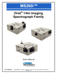
Figure 1.0 shows the big picture of the whole project. However, my
project will only focus on the router. As we know, a router is a device that
determines the proper path for data to travel between different networks, and
forwards data packets to the next device along this path. Therefore, the aim of
my project is to make sure that the router works by choosing the shortest and
correct path to send the data. The router used for this project is the Linksys
3
WRT54GL. The router must then be tested to show that it can connect to other
routers or computers and work in a mesh network.
Figure 1.0: Scope of the Project
1.4
Outline of Thesis
This thesis consists of five chapters. The first chapter is on the
introduction of the project, including its objective and scope. Chapter 2
concentrates on the theory and literature review used for this project. It
discusses about wireless mesh routing and its applications. Chapter 3 will be on
the methodology of this project. It will also include details on the steps
implemented in this project. The results and discussions of this project will be
presented in Chapter 4. The conclusion and future recommendations will be
discussed in the last chapter, Chapter 5.
CHAPTER 2
LITERATURE REVIEW
2.1
Introduction
What is a wireless network, you might ask? While the term wireless network
may technically be used to refer to any type of computer network that is wireless,
the term is most commonly used to refer to a telecommunications network whose
interconnections between nodes is implemented without the use of wires, such as a
computer network (which is a type of communications network). Wireless
telecommunications networks are generally implemented with some type of remote
information transmission system that uses electromagnetic waves, such as radio
waves, for the carrier and this implementation usually takes place at the physical
level or "layer" of the network.
Wireless networks have had a significant impact on the world as far back as
World War II. Through the use of wireless networks, information could be sent
overseas or behind enemy lines easily and quickly and more reliably. Since then
wireless networks have continued to develop and its uses have significantly grown.
Cellular phones are part of huge wireless network systems. People use these phones
daily to communicate with one another. Sending information over seas is possible
through wireless network systems using satellites and other signals to communicate
across the world. Emergency services such as the police department utilize wireless
networks to communicate important information quickly. People and businesses use
wireless networks to send and share data quickly whether it be in a small office
building or across the world.
5
Another important use for wireless networks is as an inexpensive and rapid
way to be connected to the Internet in countries and regions where the telecom
infrastructure is poor or there is a lack of resources, like most developing countries.
Compatibility issues also arise when dealing with wireless networks.
Different components not made by the same company may not work together, or
might require extra work to fix compatibility issues. Wireless networks are typically
slower than those that are directly connected through an Ethernet cable.
A wireless network is more vulnerable because anyone can try to break into a
network broadcasting a signal. Many networks offer WEP - Wired Equivalent
Privacy - security systems which have been found to be vulnerable to intrusion.
Though WEP does block some intruders, the security problems have caused some
businesses to stick with wired networks until security can be improved. Another
type of security for wireless networks is WPA - Wi-Fi Protected Access. WPA
provides more security to wireless networks than a WEP security set up. The use of
firewalls will help with security breaches which can help to fix security problems in
some wireless networks that are more vulnerable
So, why go wireless? Well, there are many reasons why a wireless
connection is better than a cabled connection. This can be seen in the Figure 2.0.
6
Figure 2.0: Network Cabling is Expensive & Difficult
There are three main topologies of a wireless network. The topologies are:
Star Topology
Mesh Topology
Star-Mesh Topology
2.1.1 Star Topology
Figure 2.1: Star Topology
7
Single-hop system in which all nodes/wireless routers are within direct
communication range (usually 30 to 100 meters) to a base (monitoring)
station
All nodes are identical and the base station serves to communicate data and
commands to the sensor end points
The base station is also used to transmit data to a higher-level control or
monitoring system
Delivers the lowest overall power consumption, but the transmission distance
of the radio limits it in each node
An example of an application using a star topology is a medical monitoring
PAN (personal area network) in each medical devices measuring patient
information such as blood pressure and glucose level can wirelessly transmit
the data to the PDA by a doctor performing rounds
2.1.2 Mesh Topology
Below are a few key points on mesh topology:
Multi-hopping systems in which all wireless sensor nodes are identical and
communicate with each other to hop data to and from the sensor nodes and
base station
Wireless sensors can also pass commands directly to each other in a mesh
network, avoiding the need to communicate with each other through a base
station
Highly fault-tolerant since each sensor node has multiple paths back to the
gateway and to other nodes. If a sensor node fails, the network will
reconfigure itself around the failed node automatically
The multi-hop system allows for much longer range than a star topology, but
it has a higher power consumption rate
These key points can be understood better by referring to Figures 2.2, 2.3 and 2.4.
8
Figure 2.2: Mesh Topology
Figure 2.3: Mesh Networks are Reliable
9
Figure 2.4: Installation is a Breeze
2.1.3 Star-Mesh Topology
Figure 2.5: Star-Mesh Topology
Seeks to take advantage of the low power and simplicity of the star topology
as well as the extended range and self-healing nature of a mesh topology
10
Organize nodes in a star topology around routers and repeaters that in turn
organize themselves in a mesh network
Routers serve both to extend the range of the network and to provide fault
tolerance
Offers the highest degree of mobility and flexibility for rapid changes to the
network populations and the lowest overall power consumption for networks
that need to stretch beyond 30 to 100 meters
2.2
Applications of Wireless Networks in Health & Medicine
There are many areas where Wireless Sensor Networks (WSN) can be used
in Health & Medicine. The trend of using WSN’s is catching on really quickly. This
technology moving forwards progressively as many big names such as Intel are
looking into WSN’s as the next generation of mobile telemedicine.
Living alone in her quiet home, Harriet often feels lonely and depressed.
Newly widowed at 82, she has little interest in physical activity and no zest for
social contact. Eating is a chore. She doesn't feel like going out for a meal, and she
doesn't feel like fixing food for herself. Consequently, Harriet's health is in serious
jeopardy. This combination of social isolation, inactivity and failing nutrition is
alarmingly common among today's aging population, but information technology
may offer the means to counteract a harmful outcome. Imagine that there's a tiny
sensor embedded in one of Harriet's walking shoes and another on the peg where she
hangs her outdoor jacket. Whenever these and other miniature sensing devices
throughout Harriet's home notice her moving in the direction of her front door, the
sensors use a wireless network to alert Sonya, across the street, and Roland, down
the block, that Harriet is about to go for a morning walk. Sonya gets the suggestion
on her television, and Roland hears it by phone: "Call Harriet now if you want to go
along for some exercise." Later the same day, Harriet learns much the same way
that cabinet doors are opening in her neighbor Ruth's kitchen. Acting on a verbal
cue that she hasn't eaten yet today, Harriet calls Ruth to suggest that they prepare
11
and eat lunch together. The two end up sharing food, activity and conversation.
Such technology scenarios may seem far-fetched, even science fiction-like,
but they are in fact close to becoming real. The key is wireless sensor networks, an
intriguing new technology model in which behavioral and biological data is
collected and analyzed for customized proactive computing applications. As the
name implies, proactive computing aims to anticipate people's needs and take action
to meet those needs on their behalf, relieving people of tedious data entry.
Another example is inside an experimental smart home at Intel’s Oregon
campus, where a sensor network is under development that could someday keep tabs
on an Alzheimer’s patient’s vital signs while reminding him how to warm up his
lunch.
Body sensors monitor vital signs such as heart and sugar. The sensor is
attached to the body like the figure below:
Figure 2.6: A Body Sensor
2.3
Applications of Wireless Mesh Networks
Mesh networks are becoming ever more popular. This is because it is
affordable, easy to manage and trusted. It has been implemented all around the
world for many different types of functions.
12
2.3.1
Athens Wireless Network
This wireless mesh network is one of the biggest mesh networks there is. It
has more than 7000 nodes and usually around 2000 nodes are active. It has 909
backbone nodes and 607 access points.
Figure 2.7: A Map of the Active Nodes in the Athens Wireless Mesh Network
13
2.3.2
Berlin FreiFunk.net
This wireless mesh network has over 600 nodes. It is also very successful
and many other wireless mesh networks have tries to emulate this particular mesh
network.
Figure 2.8: A Partial Map of the Berlin Wireless Mesh Network
2.4
Other Wireless Mesh Router/Modules
In this subtopic, the different types of wireless mesh routers/modules will be
discussed. This is done so that the different types of modules can be compared in
terms of price, hardware, software, user friendliness and etc.
2.4.1
Crossbow’s MPR 2400 (MICAz)
The MICAz is the latest generation of Motes from Crossbow Technology.
The MPR2400 (2400 MHz to 2483.5 MHz band) uses the Chipcon CC2420, IEEE
802.15.4 compliant, ZigBee ready radio frequency transceiver integrated with an
14
Atmega128L micro-controller. The same MICA2, 51 pin I/O connector, and serial
flash memory is used; all MICA2 application software and sensor boards are
compatible with the MPR2400.
Figure 2.9: The MPR 2400 and its Block Diagram
The radio used by the MPR2600 is an IEEE 802.15.4 compliant RF
transceiver designed for low-power and low-voltage wireless applications. It uses
Chipcon’s CC2420 radio that employs OQPSK with half sine pulse shaping. The
802.15.4 radio includes a DSSS (digital direct sequence spread spectrum) baseband
modem providing a spreading gain of 9 dB and an effective data rate of 250 kbps.
The radio is a highly integrated solution for wireless communication in the 2.4 GHz
unlicensed ISM band. It complies with worldwide regulations covered by ETSI EN
300 328 and EN 300 440 class 2 (Europe), FCC CFR47 Part 15 (US) and ARIB
STD-T66 (Japan).
An MPR 2400 costs 99USD which is far more expensive that the Linksys
WRT54GL. Therefore it is less economical when using it in a mesh network
because a mesh networks needs a lot of modules for it to be more efficient.
15
2.4.2
Cirronet’s Wireless Mesh Modules
Cirronet has quite a few wireless mesh modules. It is used in short to
medium-range industrial and commercial applications.
One of its products is the miniMESH DM1800. It is a single fixed channel
RF transceiver operating on either 433.92 MHz or 916.5MHz unlicensed
frequencies. It is compatible with many low-current power sources as it operates on
only 4mA in receive mode and 13.5mA in peak transmit mode. Its range is about
200meters/hop in an ‘open field’ outdoor environment. Out of all the other mesh
nodes we have discussed so far, it is the most affordable as it costs only 25USD per
node.
Another one of Cirronet’s products is the miniMESH DM1810. It is also a
single fixed channel RF transceiver operating on either 433.92 MHz or 916.5MHz
unlicensed frequencies. It operates on only 5.5mA in receive mode 28.5mA peak in
transmit mode which make sit compatible with many low-current power sources. In
an ‘open field’ outdoor environment, its range is 200meters/hop. However, it is a bit
more costly than the miniMESH 1800 as it costs 30USD per node.
Figure 2.10: The miniMESH DM1800, miniMESH 1810 and VersaMESH DM2200
Other than that, there is also the VersaMESH DM2200. Single digitally
modulated channel operating centered on 433.92 MHz and 916.5 MHz unlicensed
frequency
CHAPTER 3
METHODOLOGY
3.0
Introduction
In this project, the hardware that will be used is the Linksys WRT54GL.
When bought at the store, the Linksys WRT54GL should come with a power
adapter, a LAN cable and a CD which contains the user manual. The CD will not be
needed, but the other peripherals are important.
3.1
The Linksys WRT54GL
The Linksys WRT54GL Wireless-G Broadband Router combines the
functionalities of three devices into a single device, a wireless access point, a fourport full-duplex 10/100 Mbps switch and a router. The wireless access point lets
you connect Wireless-G or Wireless-B devices to the network while the switch
connects your wired-Ethernet devices together. The router function ties it all
together by letting your whole network share a high-speed cable or DSL Internet
connection.
The push button setup feature makes it easy to configure your wireless
devices. The WRT54GL even features TKIP and AES to protect your data and
privacy with up to 128-bit encryption.
17
With the Linksys Router at the center of your home or office network, you
can share a high-speed Internet connection, files, printers and multi-player games
with flexibility, speed, security and simplicity. Status Indicators - Port status, link
activity Compliant Standards - FCC IEEE 802.3, IEEE 802.3U, IEEE 802.11b,
IEEE 802.11g Data Link Protocol - Ethernet, Fast Ethernet, IEEE 802.11b, IEEE
802.11g Interfaces - 1x network - Ethernet 10Base-T/100Base-TX - RJ-45 ( WAN /
DMZ ), 4 x network - Ethernet 10Base-T/100Base-TX - RJ-45, 1 x network - RadioEthernet Dimensions - Height 4.8 cm x Depth 20 cm x Width 18.6 cm Weight - 0.5
kg.
Linksys released the WRT54GL in 2005 to support third-party firmware
based on Linux, after the original WRT54G line was switched from Linux to
VxWorks, starting with version 5. The WRT54GL is technically a reissue of the
version 4 WRT54G. The 1.0 version of this model has serial numbers starting with
CL7A;
version 1.1 models have serial numbers starting with CL7B and CL7C. The cost
of a Linksys WRT54GL module is RM220.
However, the specifications mentioned above will change once the project
gets going. Much of it original functionalities will be changed with the new one that
is to be uploaded that will enable it to work as a mesh router.
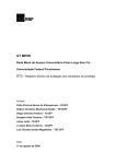
Figure 3.0: The Linksys WRT54GL (front)
18
Figure 3.1: The rear of the Linksys WRT54GL
Reset button: There are two ways to reset the router’s factory settings. Either press
the reset button and hold for 5 seconds, or by restoring the defaults in the web UI.
Internet port: The Internet port is where the Ethernet cable will be connected
1, 2, 3, 4:
These ports connect the router to the networked PCs
Power:
The Power port is where the power adapter is to be connected
Table 3.0: Specifications of the Linksys WRT54GL
Architecture
MIPS
Vendor
Broadcom
CPU Speed
200 MHz
RAM
16MB
Flash Memory
4MB
System-On-Chip
Broadcom 5352EKPB
Frequency Band
2.4 GHz
19
Figure 3.2: The Block Diagram of the WRT54GL
3.2
Work Flow and Work Breakdown
Integration of router with
PC
Update the Linksys
WRT54GL with mesh
protocol
Implement shortest path
Input main system settings
such as ESSID, BSSID,
Subnet Mask and etc
Figure 3.3 Breakdown of Work Done for the Project
3.3
Gantt Chart
Table 3.0 Gantt chart for PSM 1
Tasks for PSM1
Meet with lecturer
WEEK
1
2
Study of Telemedicine System
Study of Wireless Mesh
Network
Reverse Engineering of
Wireless Router
Measurements of Power, Signal
etc. in a Wireless Router
Design of a Wireless Mesh
Router
Algorithm Design of Mesh
Protocol
Report Writing
Proposed
Actual
3
4
5
6
7
8
9
10
11
12
13
14
Table 3.1: Gantt chart for PSM 2
WEEK
Tasks for PSM2
1
2
Meet with lecturer
Research/ Study on Routers
Testing of Router
Integration/Installation with PC
Implementation of Programming
Integration in Wireless Mesh
Network
Testing and Optimization
Report Writing
Proposed
Actual
3
4
5
6
7
8
9
10
11
12
13
14
22
3.4
Design and Implementation
The Linksys WRT54GL is a normal wireless router which can be used as an
access point. However, it will not be able to work as a mesh router with its original
setting. Changes needed to be made and these included updating it with the mesh
protocol as well as the shortest path algorithms.
3.4.1
Mesh Routing
There are many ways to implement mesh routing as there are many different
types of mesh protocols. For this project, I chose to follow the mesh protocol
Optimized Link State Routing Protocol (OLSR).
The OLSR is a proactive routing protocol. Every node sends periodically
broadcast "Hello"-messages with information to specific nodes in the network to
exchange neighbourhood information. The information includes the nodes IP,
sequence number and a list of the distance information of the nodes neighbours.
After receiving this information a node builds itself a routing table. Now the
node can calculate with the shortest path algorithm the route to every node he wants
to communicate. When a node receives an information packet with the same
sequence number twice he is going to discard it. In these routing tables he stores the
information of the route to each node in the network. The information is only
updated:
a change in the neighbourhood is detected
a route to any destination is expired
a better (shorter) route is detected for a destination
The difference from OLSR to LSR (Links State Protocol) is that OLSR relies on
multi-point relays (MPR). MPR is a node which is selected by its direct neighbour
(one hop). The first idea of multipoint relays is to minimize the flooding of
23
broadcast messages in the network. An information packet should not be sent twice
in the same region of the network. MPR helps to optimize and reduce that problem.
Each node informs its direct neighbours (one hop) about its MPR set in the "Hello"messages. After receiving such a "Hello"-message, each node records the nodes
MPR Selector that selects it as one of their MPRs. The second idea is that the size
of the hello messages is reduced. It includes only the neighbours that select node N2
as one of their MPR nodes. In this way partial topology information is propagated.
Node N2 can be reached only from its MPR selectors.
Each node in the network, in our example node N2, selected a few neighbour
nodes in the network. These nodes will send node N2-packets. These selected
nodes, N1 and N6 are called Multipoint Relays of node N2. Node N2 selects its
MPR to cover all the nodes that are exactly two hops away from it. In our example:
N7, N8, N9 and N4. A node which is not a Multipoint Relay can read the packet
sent from N2 but cannot forward it.
Figure 3.4 MPR Selection
In opposition to normal flooding (Figure 3.5(a)), only Multi point relays can forward
the messages (Figure 3.5(b)).
24
(a)
(b)
Figure 3.5 MPR Forwarding (a) Normal Flooding (b) MPR Flooding
Advantages:
minimal latency
ideal in high density and large networks
OLSR achieves more efficiency than classic LS algorithms when networks
are dense
OLSR avoids the extra work of "finding" the destination by retaining a
routing entry for each destination all the time, thus providing low singlepacket transmission latency
OLSR can easily be extended to QoS monitoring by including bandwidth
and channel quality information in link state entries. Thus, the quality of the
path (e.g., bandwidth, delay) is known prior to call setup
3.4.2 Shortest Path Algorithm
As discussed in the above subtopic, the mesh routing must implement the
shortest path algorithm. For this algorithm, the procedures are as explained below.
1. The router builds a graph of the network and identifies source and
destination nodes, as V1 and V2 for example. Then it builds a matrix, called
the "adjacency matrix." In this matrix, a coordinate indicates weight. For
25
example, [i, j] is the weight of a link between Vi and Vj. If there is no direct
link between Vi and Vj, this weight is identified as "infinity."
2. The router builds a status record set for every node on the network. The
record contains three fields:
(a)
Predecessor field - The first field shows the previous node.
(b)
Length field - The second field shows the sum of the weights from
the source to that node.
(c)
Label field - The last field shows the status of node. Each node can
have one status mode: "permanent" or "tentative."
3. The router initializes the parameters of the status record set (for all nodes)
and sets their length to "infinity" and their label to "tentative."
4. The router sets a T-node. For example, if V1 is to be the source T-node, the
router changes V1's label to "permanent." When a label changes to
"permanent," it never changes again. A T-node is an agent and nothing
more.
5. The router updates the status record set for all tentative nodes that are
directly linked to the source T-node.
6. The router looks at all of the tentative nodes and chooses the one whose
weight to V1 is lowest. That node is then the destination T-node.
7. If this node is not V2 (the intended destination), the router goes back to step
5.
8. If this node is V2, the router extracts its previous node from the status record
set and does this until it arrives at V1. This list of nodes shows the best route
from V1 to V2.
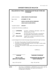
These steps are shown below in a flowchart:
26
Figure 3.6: Flowchart of Shortest Path Algorithm
A detailed explanation is as follows:
Here we want to find the best route between A and E (see below). You can
see that there are six possible routes between A and E (ABE, ACE, ABDE, ACDE,
ABDCE, ACDBE), and it's obvious that ABDE is the best route because its weight
is the lowest. But life is not always so easy, and there are some complicated cases in
which we have to use algorithms to find the best route.
As you see in the image below, the source node (A) has been chosen as Tnode, and so its label is permanent (we show permanent nodes with filled circles and
T-nodes with the --> symbol).
27
In this step, you see that the status record set of tentative nodes directly
linked to T-node (B, C) has been changed. Also, since B has less weight, it has been
chosen as T-node and its label has changed to permanent (see below).
In this step, like in step 2, the status record set of tentative nodes that have a
direct link to T-node (D, E), has been changed. Also, since D has less weight, it has
been chosen as T-node and its label has changed to permanent (see below).
In this step, we don't have any tentative nodes, so we just identify the next Tnode. Since E has the least weight, it has been chosen as T-node.
E is the destination, so we stop here.
28
We are at end. Now we have to identify the route. The previous node of E is
D, and the previous node of D is B, and B's previous node is A. So the best route is
ABDE. In this case, the total weigh is 4 (1+2+1).
3.4.3 Implementing the Algorithm Using PuTTY
PuTTY is an SSH and telnet client, developed originally by Simon Tatham
for the Windows platform. PuTTY is open source software that is available with
source code and is developed and supported by a group of volunteers.
PuTTY is a client program for the SSH, Telnet and Rlogin network
protocols. These protocols are all used to run a remote session on a computer, over
a network. PuTTY implements the client end of that session: the end at which the
session is displayed, rather than the end at which it runs.
In really simple terms: you run PuTTY on a Windows machine, and tell it to
connect to (for example) a Unix machine. PuTTY opens a window. Then, anything
you type into that window is sent straight to the Unix machine, and everything the
Unix machine sends back is displayed in the window. So you can work on the Unix
machine as if you were sitting at its console, while actually sitting somewhere else.
PuTTY does not process the commands you type into it. It's only a
communications tool. It makes a connection to another computer; it passes the
commands you type to that other computer; and it passes the other computer's
responses back to you. Therefore, the precise range of commands you can use will
not depend on PuTTY, but on what kind of computer you have connected to and
what software is running on it. The PuTTY team cannot help you with that.
Think of PuTTY as being a bit like a telephone. If you phone somebody up
and you don't know what language to speak to make them understand you, it isn't the
telephone company's job to find that out for you.
29
Figure 3.7: The PuTTY Window
There are quite a few basic commands that must be understood. If we look
at Figure 3.5; we can see that I have entered “root@192.168.1.1”. This is because
the default gateway of the WRT54GL is 192.168.1.1. By entering the command
root, we are directly accessing the WRT54GL. This is because the default username
programmed in the Linksys WRT54GL is root. Once we have accessed the Linksys,
a prompt for your password will appear. The default password is “admin”, but both
the username as well as the password can be changed later on.
30
Figure 3.8: Password Prompt
We must now unpack, compile and install the source code of the OLSR
algorithm:
# tar jxvf uolsrd-x.y.z
# od unik-olsrd-x-y.z
# make
# make install
The olsrd gets installed to /usr/bin/ and a default config file can be found under /etc
Below you can see that I have changed the directory using the cd /etc
command as I want to view the contents of the directory. I then keyed in ls –l loc*
to view the files in that directory.
31
Figure 3.9: /etc file directory
3.4.4 Main System Settings
For the mesh routing to work properly, many changes and settings need to be
made. Check out the /etc/olsrd.conf configuration files. All values in the files is
overridden with command line option clsrd. The main options to change are shown
below. Setting the “DEBUG” to 0 makes it run in the background. Setting this
higher will produce a lot more info messages on forwarding, parsing of the
configuration file etc.
# Debug level (0-9)
# If set to zero the daemon runs in the background
DEBUG
1
# IP version to use (4 to 6)
IPVERSION
6
# A list of whitespace separated interface names
INTERFACES
eth1
CHAPTER 4
RESULTS AND DISCUSSION
In this chapter of the thesis I will mainly discuss the configurations of the
Linksys WRT54GL and why those settings are chosen. I will then show the final
outcome of this project.
4.1 Router Configurations
Firstly, the most important setting is the WLAN-IP Address. I chose
10.1.1.10 for the router. However, the IP address is chosen according to the RFC
1918. When dealing with IP addresses, the RFC 1918 plays a big part as it dictates
what IP address are available and allowed to use for private network. Some IP
addresses are locked and can only be used for specific purposes.
Next is the WLAN Protocol; where the Static Protocol is chosen. This is
because a static WLAN does not automatically change its IP address. It tells the
router that all messages with the sender and receiver having an address showing the
first three groups of numbers are on the same network.
WLAN Mode must be set to ad-hoc as in ad-hoc mode where there is no
hierarchical master-client relationship. Routers can communicate directly as long as
they are within range of their wireless interfaces. Ad-hoc routers do not repeat by
default, but they can effectively do the same if routing is applied. Mesh networks
33
are based on the strategy that every mesh-enabled router acts as a relay to extend the
coverage of the wireless network.
The ESSID (Network Name) for my project is PSM_MESH and the BSSID (
this is the MAC address of the wireless interface) is 02: ca: ff: ee: ba: be. All routers
must have the same BSSID. The BSSID is important to specify to allow rejoining
mesh networks should the mesh ever break into at least 2 networks due to a
connection going down and later coming back on.
Channel is set to 6 and all routers must be on the same channel. Once again,
channel allocation must refer to the RFC 1918 as some channels are restricted in
some countries.
Beacon Interval represents the amount of time between beacon
transmissions. Before the router enters power save mode, the router needs the
beacon interval to know when to wake up to receive the beacon. After receiving a
beacon frame, each router waits for the beacon interval and then sends a beacon if
no other router does so after a random time delay. This ensures that at least one
station will send a beacon, and the random delay rotates the responsibility for
sending beacons.
By increasing the beacon interval, you can reduce the number of beacons and
associated overhead, but that will likely delay the association and roaming process
because stations scanning for available access points may miss the beacons. You
can decrease the beacon interval, which increases the rate of beacons. This will
make the association and roaming process very responsive; however, the network
will incur additional overhead and throughput will go down. As you can see, beacon
intervals are very important, after a lot of testing, I found out the most suitable
beacon interval for this project would be 100 milliseconds.
Fragmentation threshold and RTS threshold are both set to 2346 and 2347
respectively as this is the default setting for all routers. The fragmentation threshold
determines the packet size needed to activate the fragmentation of data packet into
several fragments. It improves the performances of the wireless mesh network. The
34
RTS threshold will activate the RTS/CTS handshaking mode for secure data
transfers in wireless networks.
Figure 4.0: A Part of the Configuration File of the Router
4.2 Testing and Integration with Other System
For this project, testing had to be done many times. This is because it must
work with a physiological monitoring system which is another project conducted by
another student.
35
At first, the tests were simple. I simply tested to see if other computers and
laptops could connect to the wireless router that has been set up. After that, the
testing with the physiological monitoring system began.
When computers or laptops were connected to the network, a pinging of the
PC/laptop would show if the devices are communicating with each other.
Figure 4.1: A Pinging of another Laptop in the Network
The figure above shows that the devices in the mesh network are
communicating with each other and that data is being sent and received successfully.
Figure 4.2 shows a pinging of the router itself. As you can see that the
pinging is successful so the router is working as a mesh router.
36
Figure 4.2: A Successful Pinging of the Router
After pinging is successful, the wireless router is tested to work with the
physiological monitoring system. Tests proved that the wireless mesh routing using
the Linksys WRT54GL was able to work with the system.
Figure 4.3: Integration with Physiological Monitoring System
37
Monitoring of the wireless network was also done using a networking
monitoring software. It shows when there is a lot of activity in the network. A lot of
activity is observed when the computers are communicating, i.e. when the
physiological system is in process. However, network activity is monotonous when
there is nothing going on. This can be seen in the Figure 4.4.
Figure 4.4: Network Activity
CHAPTER 5
CONCLUSION AND RECCOMENDATION
5.1 Conclusion
Mesh networks are different. As long as a node is connected to at least one
other node in a mesh network, it will have full connectivity to the entire network
because each mesh node forwards packets to other nodes in the network as required.
Mesh protocols determine the best route through the network and can dynamically
reconfigure the network if a link becomes unusable.
After buying a Linksys WRT54GL wireless router, it was successfully
updated to work as a mesh router using a mesh protocol as well as the shortest path
algorithm using PuTTY. Tests were carried out to find out if the wireless mesh
router is working as it should be. However, the most important test was to test the
router with a physiological monitoring system. This was successfully done and was
presented in the result section. It can be said that wireless mesh routing was
successfully implemented using the Linksys WRT54GL router.
5.2 Recommendation
Even though the wireless mesh routing using the Linksys WRT54GL was
successful, it would have been better if more routers were used in the tests and the
distance of each router was around 70 to 100 meters.
39
The routers must however be carefully mapped out before test can be carried
out because the 2.4 GHz frequency band used in this project is very sensitive. Trees
and plants – water on leaves negatively impact the signal. Construction materials
such as metal objects or reinforcing in walls affect the signal strength.
In existing mesh networks around the world, the networks are very complex.
Some networks have satellite connectivity and some of them are able to connect to
other networks and become one. More research and test can be done if these
complex configurations were to be carried out. The time taken to carry out such a
big project would be time consuming.
40
REFERENCES
Jack McCullough. 185 Wireless Secrets. Wiley Publishing, Inc. 2004.
Walter Glenn. Linksys Networks – The Official Guide. 3rd Edition. McGrawHill/Osborne. 2005.
Rob Tidrow. Teach Yourself Visually – Wireless Networking. 2nd Edition. Wiley
Publishing, Inc. 2006.
Danny Briere & Pat Hurley. Wireless Networks Hack and Mods for Dummies. Wiley
Publishing, Inc. 2005.
Himanshu Dwivedi. Implementing Secure Shell – Strategies For Optimizing the
Secure Shell. Wiley Publishing, Inc. 2004.
David Johnson, Karel Matthee, Dare Sokoya, Lawrence Mboweni, Ajay Makan, and
Henk Kotze. Building A Rural Wireless Mesh Network. Wireless Africa, Meraka
Institute, South Africa. 2007.
www.olsr.org
www.pmasoftware.net
www.linksys.com
41
APPENDIX A
The Configuration File for the OLSR Mesh Protocol
DebugLevel
IpVersion
0
4
AllowNoInt
FIBMetric
Pollrate
yes
"approx"
0.025
TcRedundancy
2
NatThreshold
0.75
MprCoverage
7
LinkQualityFishEye
1
LinkQualityWinSize
100
LinkQualityDijkstraLimit 0 10.0
LoadPlugin "olsrd_arprefresh.so.0.1"
{
}
RtTable 111
LoadPlugin "olsrd_nameservice.so.0.3"
{
PlParam "name"
"Diyanas_PSM"
PlParam "hosts-file"
"/var/etc/hosts"
PlParam "suffix"
".olsr"
PlParam "interval"
"180"
PlParam "timeout"
"3600"
PlParam "latlon-infile" "/var/run/latlon.txt"
PlParam "latlon-file" "/var/run/latlon.js"
}
LoadPlugin "olsrd_txtinfo.so.0.1"
{
PlParam "Accept" "127.0.0.1"
}
42
Hna4
{
192.168.1.0 255.255.255.0
}
LinkQualityLevel 2
UseHysteresis no
Interface "eth1"
{
HelloInterval
5.0
HelloValidityTime
TcInterval
TcValidityTime
MidInterval
MidValidityTime
HnaInterval
HnaValidityTime
}
125.0
2.0
500.0
25.0
500.0
25.0
500.0
43
APPENDIX B
The UDHCPD Configuration File
start
192.168.0.100
end
192.168.0.150
max_leases
50
opt
router 192.168.1.1
opt
subnet 255.255.0.0
opt
lease 43200
opt dns 81.169.139.12
opt dns 217.146.139.5
interface
br0
lease_file
/var/run/udhcpd.leases