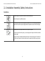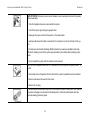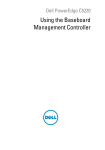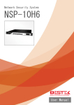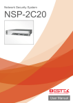
1
STRATOS S210 Series S210-X12RS Ultra-Socket High Memory 1U Rackmount Server User's Guide Version: 1.0 CONVENTIONS Conventions Several different typographic conventions are used throughout this manual. Refer to the following examples for common usage. Note: Highlights general or useful information and tips. Bold type face denotes menu items, buttons and application names. Italic type face denotes references to other sections, and the names of the folders, menus, programs, and files. <Enter> type face denotes keyboard keys. ! ! WARNING! Warning information appears before the text it references and should not be ignored as the content may prevent damage to the device. CAUTION! CAUTIONS APPEAR BEFORE THE TEXT IT REFERENCES, SIMILAR TO NOTES AND WARNINGS. CAUTIONS, HOWEVER, APPEAR IN CAPITAL LETTERS AND CONTAIN VITAL HEALTH AND SAFETY INFORMATION. Important: Indicates information that is important to know for the proper completion of a procedure, choice of an option, or completing a task. XV ACRONYMS Acronyms TERM A/D DEFINITION Analog to Digital ACPI Advanced Configuration and Power Interface ASF Alerting Standard Forum Asserted Deasserted DTC Active-high (positive true) signals are asserted when in the high electrical state (near power potential). Activelow (negative true) signals are asserted when in the low electrical state (near ground potential). BIOS Basic Input/Output System BIST Built-In Self Test BMC At the heart of the IPMI architecture is a microcontroller called the Baseboard management controller (BMC) EEPROM A signal is deasserted when in the inactive state. Activelow signal names have “_L” appended to the end of the signal mnemonic. Active-high signal names have no “_L” suffix. To reduce confusion when referring to active-high and active-low signals, the terms one/zero, high/low, and true/false are not used when describing signal states. Data Transfer Controller Electrically Erasable Programmable Read-Only Memory EMP Emergency Management Port FRU Field Replaceable Unit GB 1024 MB. GPIO General Purpose Input/Out HSC Hot-Swap Controller Circuitry connecting one computer bus to another, allowing an agent on one to access the other Hz Hertz (1 cycle/second) BSP Bootstrap processor I 2C Inter-Integrated Circuit bus Byte 8-bit quantity CLI Command Line Interface IBF Input buffer In terms of this specification, this describes the PC-AT compatible region of battery-backed 128 bytes of memory, which normally resides on the baseboard ICH I/O Controller Hub Bridge CMOS CPU IANA Central Processing Unit ICMB Intelligent Chassis Management Bus IERR Internal Error IP IPMB XVI Internet Assigned Numbers Authority Internet Protocol Intelligent Platform Management Bus ACRONYMS IPMI Intelligent Platform Management Interface NM Node Management ITP In-Target Probe OBF Output buffer KB 1024 bytes. OEM Original Equipment Manufacturer KCS Keyboard Controller Style Ohm Unit of electrical resistance KVM Keyboard, Video, Mouse PDB Power Distribution Board LAN Local Area Network PEF Platform Event Filtering LCD Liquid Crystal Display PEP Platform Event Paging LCT Lower Critical Threshold LED Light Emitting Diode POH Power-On Hours LNCT Lower Non-Critical Threshold POST Power-On Self Test LNRT Lower Non-Recoverable Threshold PWM Pulse Width Modulation LPC Low Pin Count RAC Remote Access Card LSI Large Scale Integration RAM Random Access Memory LUN Logical Unit Number MAC Media Access Control MB PERR RMCP 1024 KB MD2 Message Digest 2 – Hashing Algorithm MD5 Message Digest 5 – Hashing Algorithm – Higher Security Ms Milliseconds Mux Multiplexer NIC Network Interface Card NMI Nonmaskable Interrupt Remote Management Control Protocol ROM Read Only Memory RTC Real-Time Clock. Component of the chipset on the baseboard. RTOS Real Time Operation System SCI Serial Communication Interface SDC SCSI Daughter Card SDR Sensor Data Record SEEPROM XVII Parity Error Serial Electrically Erasable Programmable Read-Only Memory ACRONYMS SEL System Event Log SERR System Error SMBus A two-wire interface based on the I2C protocol. The SMBus is a low-speed bus that provides positive addressing for devices, as well as bus arbitration SMI Server Management Interrupt. SMI is the highest priority nonmaskable interrupt SMM Server Management Mode SMS Server Management Software SNMP SOL UART Simple Network Management Protocol Serial Over LAN Universal Asynchronous Receiver/Transmitter UCT Upper Critical Threshold UDP User Datagram Protocol UNCT Upper Non-Critical Threshold UNRT Upper Non-Recoverable Threshold WDT Watchdog Timer Word 16-bit quantity XVIII SAFETY INFORMATION Safety Information Important Safety Instructions modems attached to the server before opening it. Otherwise, personal injury or equipment damage can result. Read all caution and safety statements in this document before performing any of the instructions. Electrostatic discharge (ESD) and ESD protection: ESD can damage drives, boards, and other parts. We recommend that you perform all procedures in this chapter only at an ESD workstation. If one is not available, provide some ESD protection by wearing an antistatic wrist strap attached to chassis ground any unpainted metal surface on the server when handling parts. Warnings Heed safety instructions: Before working with the server, whether using this manual or any other resource as a reference, pay close attention to the safety instructions. Adhere to the assembly instructions in this manual to ensure and maintain compliance with existing product certifications and approvals. Use only the described, regulated components specified in this manual. Use of other products / components will void the UL listing and other regulatory approvals of the product and will most likely result in non-compliance with product regulations in the region(s) in which the product is sold. ESD and handling boards: Always handle boards carefully. They can be extremely sensitive to electrostatic discharge (ESD). Hold boards only by their edges. After removing a board from its protective wrapper or from the server, place the board component side up on a grounded, static free surface. Use a conductive foam pad if available but not the board wrapper. Do not slide board over any surface. Installing or removing jumpers: A jumper is a small plastic encased conductor that slips over two jumper pins. Some jumpers have a small tab on top that can be gripped with fingertips or with a pair of fine needle nosed pliers. If the jumpers do not have such a tab, take care when using needle nosed pliers to remove or install a jumper; grip the narrow sides of the jumper with the pliers, never the wide sides. Gripping the wide sides can damage the contacts inside the jumper, causing intermittent problems with the function controlled by that jumper. Take care to grip with, but not squeeze, the pliers or other tool used to remove a jumper, or the pins on the board may bend or break. System power on/off: The power button DOES NOT turn off the system AC power. To remove power from system, you must unplug the AC power cord from the wall outlet. Make sure the AC power cord is unplugged before opening the chassis, adding, or removing any components. Hazardous conditions, devices and cables: Hazardous electrical conditions may be present on power, telephone, and communication cables. Turn off the server and disconnect the power cord, telecommunications systems, networks, and XIX REVISION HISTORY Revision History Refer to the table below for the updates made to this manual. DATE 3/11/14 CHAPTER UPDATES Specification Ivy-Bridge plafform support BIOS Adding iSCSI and other sections BMC Adding SNMP and Quanta SMASH Copyright ties with respect to the contents hereof and specifically disclaims any implied warranties of merchantability or fitness for any particular purpose. Furthermore, the manufacturer reserves the right to revise this publication and to make changes from time to time in the content hereof without obligation of the manufacturer to notify any person of such revision or changes. Copyright © 2014 Quanta Computer Inc. This publication, including all photographs, illustrations and software, is protected under international copyright laws, with all rights reserved. Neither this manual, nor any of the material contained herein, may be reproduced without the express written consent of the manufacturer. All trademarks and logos are copyrights of their respective owners. For the latest information and updates please refer to www.QuantaQCT.com All the illustrations in this technical guide are for reference only and are subject to change without prior notice. Version 1.0.2 3/11/14 Disclaimer The information in this document is subject to change without notice. The manufacturer makes no representations or warran- XX REVISION HISTORY XXI About the Server Chapter 1 ABOUT THE SERVER INTRODUCTION 1.1 Introduction This manual is written for system technicians who are responsible for troubleshooting, upgrading, and repairing the server chassis. This document provides an overview of the hardware features of the chassis, troubleshooting information, and instructions on how to add and replace components of the multi-node server series.The document also provides information on the BIOS, and Baseboard Management Controller (BMC). For the latest version of this manual, see www.QauntaQCT.com. System Features Note: The system comprises a 1U/28.66” long chassis using 16.5” x 19.18” mainboard. The major components are featured as follows: A second processor must be installed (in processor slot 2) to activate the expansion slot and to allow the mezzanine card in there to function properly. Chipset: Intel® C602 series, upgradeable ROM kit support. Note: Expansion cards descriebed in the document are optional components. Processors (x2): Intel® Xeon processor E5-2600 / E52600 v2 product family. PCI Express: (1) PCIe x16 G3 Low profile riser slot, (1) PCIe x8 G3 Network Mezzanine slot, (1) PCIe x8 G3 SAS/ RAID Mezzanine slot. Memory: Up to twenty-four DIMM slots are available. DDR3 800/1066/1333/1600/1866 MHz RDIMM/LR-DIMM memory is supported. Storage: Up to ten 2.5" SATA/SAS hot-plug drives or four 3.5" SATA/SAS hot-plug drives. One SATADOM is optional. Network: Intel® Powerville I350GbE RJ45 or Intel® Twinville X540 10G BASE T RJ45 dual-port on board. Table 1-1: Specification Chassis type 1-1 1U Chassis ABOUT THE SERVER SYSTEM FEATURES Table 1-1: Specification (Continued) Size (L x W x H) MB factor (W x L) Table 1-1: Specification (Continued) 728.0 mm x 438.0 mm x 43.2 mm 28.6" x 17.2" x 1.7" (24) DDR3 800/1066/1333/1600/1866 MHz ECC RDIMM/LR-DIMM slots up to 768 GB System Memory 487.17 mm x 419.1 mm 19.18" x 16.5" (10) 2.5" SATA/SAS hot-plug drives, or (4) 3.5" SATA/SAS hot-plug drives (1) SATADOM (optional) Processor (2) Intel® Xeon® processor E5-2600/ E52600 V2 family, up to 130W Storage Chipset Intel® C602 (Patsburg A) HDD Backplane 1 to 1 or expander Intel® SAS controller SAS Controller (1) PCIe x16 G3 low profile riser slot (1) PCIe x8 G3 10GbE SFP+ Mezzanine slot (1) PCIe x8 G3 Quanta LSISAS/RAID Mezzanine slot Intel® C602 (Patsburg A) upgrade ROM #1 (optional) PCI Expansion Slot Intel® C602 (Patsburg A) upgrade ROM #2 (optional) Intel® C602 (Patsburg A) upgrade ROM #5 (optional) Intel® C602 (Patsburg A) upgrade ROM #6 (optional) or LSI SAS controller Quanta LSISAS 2008 Mezzanine card (optional) Quanta LSISAS 2108 Mezzanine card (optional) Quanta LSISAS 2208 Mezzanine card (optional) Quanta LSISAS 2308 Mezzanine card (optional) 1-2 ABOUT THE SERVER SYSTEM FEATURES Table 1-1: Specification (Continued) Table 1-1: Specification (Continued) Intel® SW RAID Software RAID Options Intel® RSTe SATA RAID 0/1/10 (AHCI HDD) Network Interface (2) Intel® Twinville X540 10G BASE T RJ45 ports Intel® C602 (Patsburg A) upgrade ROM #1 RAID 0/1/10 for SCU (optional) Management Port (1) Dedicated GbE RJ45 management port Intel® C602 (Patsburg A) upgrade ROM #2 RAID 0/1/10/5 for SCU (optional) Integrated Graphics BMC Aspeed AST2300 8MB DDR3 Video memory Intel® C602 (Patsburg A) upgrade ROM #5 RAID 0/1/10 for SCU (optional) Intel® C602 (Patsburg A) upgrade ROM #6 RAID 0/1/10/5 for SCU (optional) Rear I/O Interface Intel® C602 (Patsburg A) upgrade ROM #9 SATA RAID 0/1/10/5 for SCU (optional) or (2) USB 2.0 ports (1) VGA port (1) RS232 serial Port (2) GbE or 10G BASE-T RJ45 ports (1) GbE RJ45 management port (1) ID button with LED Power Supply (1) 750W high efficiency PSU, 100240VAC 50/60Hz (1) 750W high efficiency redundant PSU, 100-240VAC 50/60Hz (optional) TPM Yes (optional) RoHS Yes LSI SW RAID Quanta LSISAS 2008 mezzanine card for RAID 0/1/10 (optional) Quanta LSISAS 2308 mezzanine card for RAID 0/1/10 (optional) Quanta LSISAS2208 PD-32 mezzanine card for RAID 0/1/10/5 (optional) Quanta LSISAS2208 PD-32 mezzanine card + LSI RAID 6 Key for RAID 0/1/10/5/ 6/50/60 (optional) Systems Management Hardware RAID Options (2) Intel® Powerville I350 GbE RJ45 ports, or 1-3 IPMI v2.0 Compliant On board "KVM over IP" support ABOUT THE SERVER PACKAGE CONTENTS Package Contents The following list includes the package components: (1) 1U chassis system (1) Mainboard modules (2) Processor heatsinks (1) Power supply (1) Power cord (Optional) (1) CD (user manual included) (1) Rail kit 1-4 ABOUT THE SERVER A TOUR OF THE SYSTEM 1.2 A Tour of the System The system is available as a 2.5” or a 3.5” form factor. The following illustrations show the major component parts of these two variants. 2.5” HDD System Table 1-2: 2.5” HDD System Component Overview NO. 1 7 ITEM DESCRIPTION 1 Riser Assembly (1) PCIe x16 G3 low profile riser slot (1) PCIe x8 G3 10GbE SFP+ Mezzanine slot (1) PCIe x8 G3 Quanta LSISAS/RAID Mezzanine slot 2 Hot-Swap PSU (2) Power supply units 3 Front Panel Control and LED panel for system status 4 2.5” Hard Drives (10) 2.5” hard disk drives (HDD) 5 System Fan (6) Fan module assembly 6 Air Duct Maintains proper airflow throughout system 7 iBBU holder Backup battery unit for mezzanine expansion card 2 6 5 4 Figure 1-1. 3 2.5” HDD System Component Overview 1-5 ABOUT THE SERVER 3.5” HDD SYSTEM 3.5” HDD System Table 1-3: 3.5” HDD System Component Description 1 6 NO . DESCRIPTION Riser Assembly (1) PCIe x16 G3 low profile riser slot (1) PCIe x8 G3 10GbE SFP+ Mezzanine slot (1) PCIe x8 G3 Quanta LSISAS/RAID Mezzanine slot 2. Hot-Swap PSU (2) Power supply units 3. Front Panel Control and LED panel for system status 4. iBBU holder Backup battery unit for mezzanine expansion card 5. 3.5 Hard Drives (4) 3.5” hard disk drives (HDD) 6. System Fan (6) Fan module assembly 7. Air Duct Maintains proper airflow throughout system 1. 2 7 3 5 4 Figure 1-2. ITEM 3.5” HDD System Component Description 1-6 ABOUT THE SERVER 3.5” HDD SYSTEM 3.5” HDD System Front Features 1 2 Figure 1-3. 3.5” HDD System Front Features 3.5” HDD System Front Panel Definition 3.5” HDD System Front Control Panel Table 1-4: 3.5” HDD Front Panel Definition ITEM NAME 1 2 3 4 5 6 7 DESCRIPTION 1 Control Panel Connect USB devices to these ports 2 HDD Bays Insert HDDs here. Table 1-5: 3.5” HDD System LED Function and Behavior ITEM 1 1-7 ICON NAME Front USB ports DESCRIPTION Connect USB devices to these ports 8 ABOUT THE SERVER 3.5” HDD SYSTEM Table 1-5: 3.5” HDD System LED Function and Behavior (Continued) Table 1-5: 3.5” HDD System LED Function and Behavior (Continued) ITEM ICON NAME DESCRIPTION Reset Button with LED Base system On Push button to Reset system 3 MGMT LED Green On, link Green Blinking, LAN access 4 LAN 2/1 LED Green On, link Green Blinking, LAN access 5 HDD Activity LED Green Blinking, HDD access Off, no access Event LED Amber Blinking Critical failure: fan, voltage, temperature state Non-critial failure: fan, voltage, temperature state, CPU, thermal trip Off SEL cleared, DC Off, last pending warning/error de-asserted ID Button with LED Blue On Selected unit ID Off No ID requested 2 6 7 ITEM 8 ICON NAME Power button with LED DESCRIPTION Green On Off System off Turn system on / off. 1-8 ABOUT THE SERVER 3.5” HDD SYSTEM 2.5” HDD System Front Features 1 2 Figure 1-4. 2.5” HDD System Front Features 2.5” HDD System Front Panel Definition 2.5” HDD System Front Control Panel Table 1-6: 2.5” HDD Front Panel Definition ITEM NAME DESCRIPTION 1 Control Panel Connect USB devices to these ports 2 HDD Bays Insert HDDs here. 1 3 2 4 Figure 1-5. 1-9 Control Panel ABOUT THE SERVER 3.5” HDD SYSTEM Table 1-7: 2.5” HDD LED Function and Behavior ITEM ICON NAME DESCRIPTION 1 Event LED Amber Blinking Critical failure: fan, voltage, temperature state Non-critial failure: fan, voltage, temperature state, CPU, thermal trip Off SEL cleared, DC Off, last pending warning/error de-asserted 2 LAN1/2 LED Green ON, link Green Blinking, LAN access 3 Power Button with LED Green On Off System off Turn system on / off 4 ID button with LED Blue On Selected unit ID Off No ID requested 1-10 ABOUT THE SERVER SYSTEM HDD INTRODUCTION System HDD Introduction This system is available in two form factors, 2.5” HDD and 3.5” HDD. 2.5” Hard Disk Drive Configuration HDD 0 HDD 2 HDD 4 HDD 6 HDD 8 HDD 1 HDD 3 HDD 5 HDD 7 HDD 9 Figure 1-6. 2.5” HDD Configuration 3.5” Hard Disk Drive Configuration HDD 0 HDD 1 HDD 2 Figure 1-7. 3.5” HDD Configuration 1-11 HDD 3 ABOUT THE SERVER SYSTEM REAR FEATURES System Rear Features System Rear View 1 3 4 Figure 1-8. 6 7 8 9 Table 1-8: System I/O Features (Continued) FEATURE 10GbE SFP+ Port Optional 2 PCIe Card PCIe x16 G3 card PSU Power supply unit Left: PSU1 Right: PSU0 4 ID button Press this to illuminate the ID LED on the front panel 5 VGA port Connect a monitor to this port 6 Console port Connect a serial cable to this port 7 USB port (2) USB 2.0 ports FEATURE ITEM DESCRIPTION 1 3 5 I/O Features (shown with ports on Mezzanine card) Table 1-8: System I/O Features ITEM 2 DESCRIPTION 8 GbE (or 10GbE) LAN port Connect this to the data network 9 Dedicated Management LAN Port Connect this to a network monitoring station Note: The system supports single and redundant PSU. Redundant PSU is optional. 1-12 ABOUT THE SERVER SYSTEM REAR FEATURES System I/O LED Description Rear I/O LED Description Table 1-9: Rear side LED Function and Behavior (1G LAN) ICON NAME COLOR Identification LED Blue CONDITION ON Unit selected for identification OFF No identification requested On Link/Act LAN1 LED (Right) Speed Green Blinking LAN2 LED (Left) Speed LAN Link LAN access (off when there is traffic) OFF Disconnect Green ON Link speed is 100Mbits/sec Amber ON Link speed is 1000Mbits/sec -- OFF OFF, link speed is 10Mbits/sec On Link/Act DESCRIPTION Green Blinking LAN Link LAN access (off when there is traffic) OFF Disconnect Green ON Link speed is 100Mbits/sec Amber ON Link speed is 1000Mbits/sec -- OFF OFF, link speed is 10Mbits/sec 1-13 ABOUT THE SERVER SYSTEM REAR FEATURES Table 1-9: Rear side LED Function and Behavior (1G LAN) (Continued) NAME ICON COLOR CONDITION DESCRIPTION On Service Port (LAN 3) LED Link/Act Speed Green LAN Link Blinking Green LAN access (off when there is traffic) OFF Disconnect ON Link speed is 10/100/1000Mbits/sec Table 1-10: Rear side LED Function and Behavior (10G LAN) NAME COLOR Identification LED Blue ICON CONDITION DESCRIPTION ON Unit selected for identification OFF No identification requested On Link/Act LAN1 LED (Right) Speed Green Blinking LAN Link LAN access (off when there is traffic) OFF Disconnect Blue ON Link speed is 10Gbits/sec Amber ON Link speed is 1Gbits/sec -- OFF Link speed is 10/100Mbits/ sec 1-14 ABOUT THE SERVER SYSTEM REAR FEATURES Table 1-10: Rear side LED Function and Behavior (10G LAN) (Continued) NAME ICON COLOR CONDITION On Link/Act LAN2 LED (Left) Speed Green Blinking LAN access (off when there is traffic) Disconnect Blue ON Link speed is 10Gbits/sec Amber ON Link speed is 1Gbits/sec -- OFF Link speed is 10/100Mbits/ sec Green Service Port (LAN 3) LED Speed LAN Link OFF On Link/Act DESCRIPTION Green 1-15 Blinking LAN Link LAN access (off when there is traffic) OFF Disconnect ON Link speed is 10/100/ 1000Mbits/sec OFF Disconnect Installation and Assembly Safety Instructions Chapter 2 INSTALLATION AND ASSEMBLY SAFETY INSTRUCTIONS INSTALLATION ASSEMBLY SAFETY INSTRUCTIONS 2.1 Installation Assembly Safety Instructions Guidelines The power supply in this product contains no user-serviceable parts. Refer servicing only to qualified personnel. Do not attempt to modify or use the supplied AC power cord if it is not the exact type required. A product with more than one power supply will have a separate AC power cord for each supply. The power button on the system does not turn off system AC power. To remove AC power from the system, you must unplug each AC power cord from the wall outlet or power supply. The power cord(s) is considered the disconnect device to the main (AC) power. The socket outlet that the system plugs into shall be installed near the equipment and shall be easily accessible. 2-1 INSTALLATION AND ASSEMBLY SAFETY INSTRUCTIONS GUIDELINES SAFETY STEPS: Whenever you remove the chassis covers to access the inside of the system, follow these steps: 1. Turn off all peripheral devices connected to the system. 2. Turn off the system by pressing the power button. 3. Unplug all AC power cords from the system or from wall outlets. 4. Label and disconnect all cables connected to I/O connectors or ports on the back of the system. 5. Provide some electrostatic discharge (ESD) protection by wearing an antistatic wrist strap attached to chassis ground of the system-any unpainted metal surface-when handling components. 6. Do not operate the system with the chassis covers removed. After you have completed the six SAFETY steps above, you can remove the system covers. To do this: 1. Unlock and remove the padlock from the back of the system if a padlock has been installed. 2. Remove and save all screws from the covers. 3. Remove the cover(s). A microprocessor and heat sink may be hot if the system has been running. Also, there may be sharp pins and edges on some board and chassis parts. Contact should be made with care. Consider wearing protective gloves. 2-2 INSTALLATION AND ASSEMBLY SAFETY INSTRUCTIONS GUIDELINES For proper cooling and airflow, always reinstall the chassis covers before turning on the system. Operating the system without the covers in place can damage system parts. To install the covers: 1. Check first to make sure you have not left loose tools or parts inside the system. 2. Check that cables, add-in cards, and other components are properly installed. 3. Attach the covers to the chassis with the screws removed earlier, and tighten them firmly. 4. Insert and lock the padlock to the system to prevent unauthorized access inside the system. 5. Connect all external cables and the AC power cord(s) to the system. Danger of explosion if the battery is incorrectly replaced. Replace only with the same or equivalent type recommended by the equipment manufacturer. Dispose of used batteries according to manufacturer's instructions. 2-3 INSTALLATION AND ASSEMBLY SAFETY INSTRUCTIONS GUIDELINES The system is designed to operate in a typical office environment. Choose a site that is: Clean and free of airborne particles (other than normal room dust). Well ventilated and away from sources of heat including direct sunlight. Away from sources of vibration or physical shock. Isolated from strong electromagnetic fields produced by electrical devices. In regions that are susceptible to electrical storms, we recommend you plug your system into a surge suppressor and disconnect telecommunication lines to your modem during an electrical storm. Provided with a properly grounded wall outlet. Provided with sufficient space to access the power supply cord(s), because they serve as the product's main power disconnect. The server system is safety certified as rack-mounted equipment for use in a server room or computer room, using the customer rack kit. The rail racks are designed to carry only the weight of the server system. Do not place additional load onto any railmounted equipment. System rack kits are intended to be installed in a rack by trained service technicians. Heavy object. Indicates two people are required to safely handle the system. 2-4 Safety Information Chapter 3 SAFETY INFORMATION SERVER SAFETY INFORMATION 3.1 Server Safety Information Safety Warnings and Cautions To reduce the risk of bodily injury, electrical shock, fire, and equipment damage, read this document and observe all warnings and precautions in this guide before installing or maintaining your server product. To avoid personal injury or property damage, before you begin installing the product, read, observe, and adhere to all of the following safety instructions and information. The following safety symbols may be used throughout the documentation and may be marked on the product and / or the product packaging. In the event of a conflict between the information in this document and information provided with the product or on the website for a particular product, the product documentation takes precedence. Table 9-1: Safety Warning and Cautions Your server should be integrated and serviced only by technically qualified persons. You must adhere to the guidelines in this guide and the assembly instructions in your server manuals to ensure and maintain compliance with existing product certifications and approvals. Use only the described, regulated components specified in this guide. Use of other products / components will void the UL Listing and other regulatory approvals of the product, and may result in noncompliance with product regulations in the region(s) in which the product is sold. CAUTION Indicates the presence of a hazard that may cause minor personal injury or property damage if the CAUTION is ignored. WARNING Indicates the presence of a hazard that may result in serious personal injury if the WARNING is ignored. Indicates potential hazard if indicated information is ignored. Indicates shock hazards that result in serious injury or death if safety instructions are not followed. Indicates hot components or surfaces. Indicates do not touch fan blades, may result in injury. 3-1 SAFETY INFORMATION INTENDED APPLICATION USES Table 9-1: Safety Warning and Cautions this product for other product categories and environments (such as medical, industrial, residential, alarm systems, and test equipment), other than an ITE application, may require further evaluation. Indicates to unplug all AC power cord(s) to disconnect AC power. Please recycle battery. Site Selection The rail racks are designed to carry only the weight of the server system. Do not use rail-mounted equipment as a workspace. Do not place additional load onto any rail-mounted equipment. The system is designed to operate in a typical office environment. Choose a site that is: Indicates two people are required to safely handle the system. Restricted Access Location: The server is intended for installation only in a Server Room or Computer Room where both these conditions apply: access can only be gained by SERVICE PERSONS or by USERS who have been instructed about the reasons for the restrictions applied to the location and about any precautions that shall be taken; and access is through the use of a TOOL or lock and key, or other means of security, and is controlled by the authority responsible for the location. Clean, dry, and free of airborne particles (other than normal room dust). Well-ventilated and away from sources of heat including direct sunlight and radiators. Away from sources of vibration or physical shock. Isolated from strong electromagnetic fields produced by electrical devices. In regions that are susceptible to electrical storms, we recommend you plug your system into a surge suppressor and disconnect telecommunication lines to your modem during an electrical storm. Provided with a properly grounded wall outlet. Provided with sufficient space to access the power supply cord(s), because they serve as the product's main power disconnect. Provided with either two independent AC power sources or two independent phases from a s single source. Intended Application Uses This product was evaluated as Information Technology Equipment (ITE), which may be installed in offices, schools, computer rooms, and similar commercial type locations. The suitability of 3-2 SAFETY INFORMATION EQUIPMENT HANDLING PRACTICES Equipment Handling Practices ! Reduce the risk of personal injury or equipment damage: Conform to local occupational health and safety requirements when moving and lifting equipment. Use mechanical assistance or other suitable assistance when moving and lifting equipment. To reduce the weight for easier handling, remove any easily detachable components. ! ! Power and Electrical Warnings ! CAUTION! THE POWER BUTTON, INDICATED BY THE STAND-BY POWER MARKING, DOES NOT COMPLETELY TURN OFF THE SYSTEM AC POWER, 5V STANDBY POWER IS ACTIVE WHENEVER THE SYSTEM IS PLUGGED IN. TO REMOVE POWER FROM SYSTEM, YOU MUST UNPLUG THE AC POWER CORD FROM THE WALL OUTLET. YOUR SYSTEM MAY USE MORE THAN ONE AC POWER CORD. MAKE SURE ALL AC POWER CORDS ARE UNPLUGGED. MAKE SURE THE AC POWER CORD(S) IS / ARE UNPLUGGED BEFORE YOU OPEN THE CHASSIS, OR ADD OR REMOVE ANY NON HOT-PLUG COMPONENTS. ! CAUTION! SOME POWER SUPPLIES IN SERVERS USE NEUTRAL POLE FUSING. TO AVOID RISK OF SHOCK USE CAUTION WHEN WORKING WITH POWER SUPPLIES THAT USE NEUTRAL POLE FUSING. CAUTION! THE POWER SUPPLY IN THIS PRODUCT CONTAINS NO USERSERVICEABLE PARTS. DO NOT OPEN THE POWER SUPPLY. HAZARDOUS VOLTAGE, CURRENT AND ENERGY LEVELS ARE PRESENT INSIDE THE POWER SUPPLY. RETURN TO MANUFACTURER FOR SERVICING. CAUTION! WHEN REPLACING A HOT-PLUG POWER SUPPLY, UNPLUG THE POWER CORD TO THE POWER SUPPLY BEING REPLACED BEFORE REMOVING IT FROM THE SERVER. ! CAUTION! ! CAUTION! SOME POWER SUPPLIES IN SERVERS USE NEUTRAL POLE FUSING. TO AVOID RISK OF SHOCK USE CAUTION WHEN WORKING WITH POWER SUPPLIES THAT USE NEUTRAL POLE FUSING. DO NOT ATTEMPT TO MODIFY OR USE AN AC POWER CORD IF IT IS NOT THE EXACT TYPE REQUIRED. A SEPARATE AC CORD IS REQUIRED FOR EACH SYSTEM POWER SUPPLY. 3-3 CAUTION! TO AVOID RISK OF ELECTRIC SHOCK, TURN OFF THE SERVER AND DISCONNECT THE POWER CORD, TELECOMMUNICATIONS SYSTEMS, NETWORKS, AND MODEMS ATTACHED TO THE SERVER BEFORE OPENING IT. SAFETY INFORMATION SYSTEM ACCESS WARNINGS System Access Warnings Power Cord Warnings If an AC power cord was not provided with your product, purchase one that is approved for use in your country. ! ! CAUTION! Turn off all peripheral devices connected to this product. Turn off the system by pressing the power button to off. Disconnect the AC power by unplugging all AC power cords from the system or wall outlet. Disconnect all cables and telecommunication lines that are connected to the system. Retain all screws or other fasteners when removing access cover(s). Upon completion of accessing inside the product, refasten access cover with original screws or fasteners. Do not access the inside of the power supply. There are no serviceable parts in the power supply. Return to manufacturer for servicing. Power down the server and disconnect all power cords before adding or replacing any non hot-plug component. When replacing a hot-plug power supply, unplug the power cord to the power supply being replaced before removing the power supply from the server. Do not attempt to modify or use the AC power cord(s) if they are not the exact type required to fit into the grounded electrical outlets. The power cord(s) must meet the following criteria: The power cord must have an electrical rating that is greater than that of the electrical current rating marked on the product. CAUTION! ! ! THE POWER SUPPLY CORD(S) IS / ARE THE MAIN DISCONNECT DEVICE TO AC POWER. THE SOCKET OUTLET(S) MUST BE NEAR FOLLOWING SAFETY INSTRUCTIONS APPLY WHENEVER ACCESSING THE INSIDE OF THE PRODUCT: TO AVOID ELECTRICAL SHOCK OR FIRE, CHECK THE POWER CORD(S) THAT WILL BE USED WITH THE PRODUCT AS FOLLOWS: THE POWER CORD MUST HAVE SAFETY GROUND PIN OR CONTACT THAT IS SUITABLE FOR THE ELECTRICAL OUTLET. CAUTION! TO AVOID PERSONAL INJURY OR PROPERTY DAMAGE, THE CAUTION! THE EQUIPMENT AND READILY ACCESSIBLE FOR DISCONNECTION. ! ! CAUTION! THE POWER SUPPLY CORD(S) MUST BE PLUGGED INTO SOCKETOUTLET(S) THAT IS /ARE PROVIDED WITH A SUITABLE EARTH GROUND. 3-4 CAUTION! IF THE SERVER HAS BEEN RUNNING, ANY INSTALLED PROCESSOR(S) AND HEAT SINK(S) MAY BE HOT. SAFETY INFORMATION ! ! RACK MOUNT WARNINGS Rack Mount Warnings CAUTION! UNLESS YOU ARE ADDING OR REMOVING A HOT-PLUG COMPONENT, ALLOW THE SYSTEM TO COOL BEFORE OPENING THE COVERS. TO AVOID THE POSSIBILITY OF COMING INTO CONTACT WITH HOT COMPONENT(S) DURING A HOT-PLUG INSTALLATION, BE CAREFUL WHEN REMOVING OR INSTALLING THE HOT-PLUG COMPONENT(S). The following installation guidelines are required by UL for maintaining safety compliance when installing your system into a rack. The equipment rack must be anchored to an unmovable support to prevent it from tipping when a server or piece of equipment is extended from it. The equipment rack must be installed according to the rack manufacturer's instructions. CAUTION! TO AVOID INJURY DO NOT CONTACT MOVING FAN BLADES. IF YOUR SYSTEM IS SUPPLIED WITH A GUARD OVER THE FAN, DO NOT OPERATE THE SYSTEM WITHOUT THE FAN GUARD IN PLACE. Install equipment in the rack from the bottom up, with the heaviest equipment at the bottom of the rack. Extend only one piece of equipment from the rack at a time. You are responsible for installing a main power disconnect for the entire rack unit. This main disconnect must be readily accessible, and it must be labeled as controlling power to the entire unit, not just to the server(s). To avoid risk of potential electric shock, a proper safety ground must be implemented for the rack and each piece of equipment installed in it. Elevated Operating Ambient - If installed in a closed or multiunit rack assembly, the operating ambient temperature of the rack environment may be greater than room ambient. Therefore, consideration should be given to installing the equipment in an environment compatible with the maximum ambient temperature (Tma) specified by the manufacturer. 3-5 SAFETY INFORMATION ELECTROSTATIC DISCHARGE (ESD) Electrostatic Discharge (ESD) Reduced Air Flow - Installation of the equipment in a rack should be such that the amount of air flow required for safe operation of the equipment is not compromised. ! Mechanical Loading - Mounting of the equipment in the rack should be such that a hazardous condition is not achieved due to uneven mechanical loading. CAUTION! ESD CAN DAMAGE DRIVES, BOARDS, AND OTHER PARTS. WE RECOMMEND THAT YOU PERFORM ALL PROCEDURES AT AN ESD WORKSTATION. IF ONE IS NOT AVAILABLE, PROVIDE SOME ESD PROTECTION BY WEARING AN ANTISTATIC WRIST STRAP ATTACHED TO CHASSIS GROUND Circuit Overloading - Consideration should be given to the connection of the equipment to the supply circuit and the effect that overloading of the circuits might have on overcurrent protection and supply wiring. Appropriate consideration of equipment nameplate ratings should be used when addressing this concern. -- ANY UNPAINTED METAL SURFACE -- ON YOUR SERVER WHEN HANDLING PARTS. Always handle boards carefully. They can be extremely sensitive to ESD. Hold boards only by their edges. After removing a board from its protective wrapper or from the server, place the board component side up on a grounded, static free surface. Use a conductive foam pad if available but not the board wrapper. Do not slide board over any surface. Reliable Earthing - Reliable earthing of rack-mounted equipment should be maintained. Particular attention should be given to supply connections other than direct connections to the branch circuit (e.g. use of power strips). 3-6 SAFETY INFORMATION OTHER HAZARDS Other Hazards Cooling and Airflow Battery Replacement ! ! CAUTION! THERE IS THE DANGER OF EXPLOSION IF THE BATTERY IS INCORRECTLY REPLACED. WHEN REPLACING THE BATTERY, USE ONLY THE BATTERY RECOMMENDED BY THE EQUIPMENT MANUFACTURER. ! ! CAUTION! CAREFULLY ROUTE CABLES AS DIRECTED TO MINIMIZE AIRFLOW BLOCKAGE AND COOLING PROBLEMS. FOR PROPER COOLING AND AIRFLOW, OPERATE THE SYSTEM ONLY WITH THE CHASSIS COVERS INSTALLED. OPERATING THE SYSTEM WITHOUT THE COVERS IN PLACE CAN DAMAGE SYSTEM PARTS. TO INSTALL THE COVERS: Check first to make sure you have not left loose tools or parts inside the system. Check that cables, add-in cards, and other components are properly installed. Attach the covers to the chassis according to the product instructions. CAUTION! DISPOSE OF BATTERIES ACCORDING TO LOCAL ORDINANCES AND REGULATIONS. Laser Peripherals or Devices CAUTION! DO NOT ATTEMPT TO RECHARGE A BATTERY. CAUTION! ! ! CAUTION! DO NOT ATTEMPT TO DISASSEMBLE, PUNCTURE, OR OTHERWISE DAMAGE A BATTERY. TO AVOID RISK OF RADIATION EXPOSURE AND / OR PERSONAL INJURY: Do not open the enclosure of any laser peripheral or device. Laser peripherals or devices are not serviceable. Return to manufacturer for servicing. Use certified and rated Laser Class I for Optical Transceiver product. 3-7 Regulatory and Compliance Information Chapter 4 REGULATORY AND COMPLIANCE INFORMATION PRODUCT REGULATORY COMPLIANCE MARKINGS 4.1 Product Regulatory Compliance Markings This product is marked with the following Product Certification markings: Table 10-1: Product Regulatory Compliance Markings (Continued) Table 10-1: Product Regulatory Compliance Markings REGULATORY COMPLIANCE REGION cULus Listing Marks USA / Canada CE Mark Europe FCC Marking (Class A) VCCI Marking (Class A) USA MARKING This device complies with Part 15 of the FCC Rules. Operation of this device is subject to the following two conditions: (1) This device may not cause harmful interference, and (2) This device must accept any interference received, including interference that may cause undesired operation. Japan 4-1 BSMI Certification Number & Class A Warning Taiwan KCC Korea GOST R Marking Russia REGULATORY AND COMPLIANCE INFORMATION PRODUCT REGULATORY COMPLIANCE MARKINGS Table 10-1: Product Regulatory Compliance Markings (Continued) This Class A digital apparatus complies with Canadian ICES003. ICES Canada Cet appareil numérique de la classe A est conforme à la norme NMB-003 du Canada. Recycling Package Mark Other than China 4-2 REGULATORY AND COMPLIANCE INFORMATION ELECTROMAGNETIC COMPATIBILITY NOTICES Electromagnetic Compatibility Notices FCC Verification Statement (USA) This device complies with Part 15 of the FCC Rules. Operation is subject to the following two conditions: (1) this device may not cause harmful interference, and (2) this device must accept any interference received, including interference that may cause undesired operation. Any changes or modifications not expressly approved by the grantee of this device could void the user's authority to operate the equipment. The customer is responsible for ensuring compliance of the modified product. Only peripherals (computer input/output devices, terminals, printers, etc.) that comply with FCC Class A or B limits may be attached to this computer product. Operation with noncompliant peripherals is likely to result in interference to radio and TV reception. This equipment has been tested and found to comply with the limits for a Class A digital device, pursuant to Part 15 of the FCC Rules. These limits are designed to provide reasonable protection against harmful interference in a residential installation. This equipment generates, uses, and can radiate radio frequency energy and, if not installed and used in accordance with the instructions, may cause harmful interference to radio communications. However, there is no guarantee that interference will not occur in a particular installation. If this equipment does cause harmful interference to radio or television reception, which can be determined by turning the equipment off and on, the user is encouraged to try to correct the interference by one or more of the following measures: Reorient or relocate the receiving antenna. Increase the separation between the equipment and the receiver Connect the equipment to an outlet on a circuit other than the one to which the receiver is connected. Consult the dealer or an experienced radio/TV technician for help. All cables used to connect to peripherals must be shielded and grounded. Operation with cables, connected to peripherals, that are not shielded and grounded may result in interference to radio and TV reception. Europe (CE Declaration of Conformity) This product has been tested in accordance too, and complies with the Low Voltage Directive (73/23/EEC) and EMC Directive (89/336/EEC). The product has been marked with the CE Mark to illustrate its compliance. 4-3 REGULATORY AND COMPLIANCE INFORMATION VCCI (JAPAN) VCCI (Japan) KCC (Korea) ( Korean Communications Commission (KCC) Class A Statement: English translation of the notice above: This is a Class A product based on the standard of the Voluntary Control Council for Interference (VCCI) from Information Technology Equipment. If this is used near a radio or television receiver in a domestic environment, it may cause radio interference. Install and use the equipment according to the instruction manual. Regulated Specified Components To maintain the UL listing and compliance to other regulatory certifications and/or declarations, the following regulated components must be used and conditions adhered to. Interchanging or use of other component will void the UL listing and other product certifications and approvals. BSMI (Taiwan) The BSMI Certification Marking and EMC warning is located on the outside rear area of the product. Updated product information for configurations can be found on the site at the following URL: www.quantaqct.com If you do not have access to the Web address, please contact your local representative. 4-4 Add-in cards: must have a printed wiring board flammability rating of minimum UL94V-1. Add-in cards containing external power connectors and/or lithium batteries must be UL recognized or UL listed. Any add-in card containing REGULATORY AND COMPLIANCE INFORMATION RESTRICTION OF HAZARDOUS SUBSTANCES (ROHS) COMPLIANCE modem telecommunication circuitry must be UL listed. In addition, the modem must have the appropriate telecommunications, safety, and EMC approvals for the region in which it is sold. Product recycling and end-of-life take-back systems and requirements vary by country. Contact the retailer or distributor of this product for information about product recycling and / or take-back. Quanta® Computer Inc. has a system in place to restrict the use of banned substances in accordance with the European Directive 2002/95/EC. Compliance is based on declaration that materials banned in the RoHS Directive are either (1) below all applicable threshold limits or (2) an approved / pending RoHS exemption applies. RoHS implementation details are not fully defined and may change. Threshold limits and banned substances are noted below: Quantity limit of 0.1% by mass (1000 PPM) for: Lead Mercury Hexavalent Chromium Cadmium End of Life / Product Recycling Restriction of Hazardous Substances (RoHS) Compliance Quantity limit of 0.01% by mass (100 PPM) for: Peripheral Storage Devices: must be UL recognized or UL listed accessory and TUV or VDE licensed. Maximum power rating of any one device is 19 watts. Total server configuration is not to exceed the maximum loading conditions of the power supply. Polybrominated Biphenyls Diphenyl Ethers (PBDE) 4-5