1
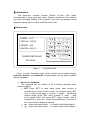
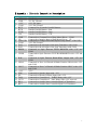
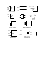
ZDJ Series
ZDJ-SRIII Microcontroller
User’s Manual
© Sunrise Electric Co.,Ltd
Phone:86-571-88994699, 88994633
http://www.sunrise-electric.com
Copyright Notice
This document is copyrighted 2005 by Sunrise Electric Co.,Ltd. All rights are reserved.
Sunrise Electric Co.,Ltd reserves the right to make improvements to the products
described in this manual at any time without notice.
No part of this manual may be reproduced, copied, translated or transmitted in any form
or by any means without the prior written permission of Sunrise Electric. Information
provided in this manual is intended to be accurate and reliable. However, Sunrise Electric
assumes no responsibility for its use, nor for any infringements upon the rights of third
parties which may result from its use.
Printed in P.R.China July 2005
2
§Introduction
This document contains Sunrise Electric Co.,Ltd’s ZDJ series
microcontroller’s using guide and notice. Operator should use the machine
only after thoroughly reading of this manual. If you have any problem during
operation, please refer to Notice and FAQ section first.
§How to use
PASSEL: 100
TOTALS: 12345
RSPEED: 400
LENGTH: 6000.0
MICROCONTROLLER
ZDJ-SRIII
figure 1.
www.sunrise−motor.com
Controller Panel
Figure 1 shows Controller panel, which contains three function blocks:
keyboard, display, and trademark. All parameters can be easily modified
through keyboard.
1. How to use keyboard
The keyboard has 14 buttons in all. Following describes each
button’s function.
¾ SET: Press ‘SET’ to enter setup mode, each function is
identified by its unique function name. For example, press ‘SET’
once to enter setup page 1, function 1: length - modify bag
making length; press ‘SET’ twice, function 2: curve - drag
motor speed. Each time press ‘SET’ button, funtion code is
increased by 1 ,then can modify other parameters. The color of
the current set line displays reversely.
¾ ←: when enter setup mode, ‘←’is used to left shift shining bit
¾ →: when enter setup mode, ‘→’is used to right shift shining bit
3
¾ ↑: when enter setup mode, ‘↑’is used to increase shining bit
by 1 with carry.
¾ ↓: when enter setup mode, ‘↓’is used to decrease shining bit
by 1 with carry.
¾ CL A: clr all, is used to clear totally bag group to zero
¾ CLR: is used to clear current bag passel or group to zero
¾ CW: is used to jog step motor forward
¾ CCW: is used to jog step motor backward
¾ F/S: is used to alter between two operate mode: fast detect and
slow detect, disabled when making blank bag. Fast detect mode
is mainly used for normal bag making, slow detect is for test
purpose mainly
¾ P/B: is used to choose making blank bag or printed bag
¾ B/W: is used to choose optic detector’s operation mode, the
LED inside button indicates if the color mark is detected by optic
detector, if yes it is light, or it is dark
¾ RUN: is used to start running. The LED inside indicates if it is on
running mode
¾ STOP: is used to stop running. The LED inside indicates if it is
normal stop(GREEN LIGHT) or error stop(RED LIGHT)。
2. How to understand LED indicator
¾ F/S:red,fast detect light, slow detect dark.
¾ P/B:red, printed bag light;blank bag dark.
¾ B/W:red,when the color mark is detected it is light, or it is dark.
¾ RUN:green,run light;stop dark.
¾ STOP:red and green,normal stop green light;over speed or
error stop red light. Before run, all dark.
¾ PORTA:red,drag port ,when light , step motor begin work.
¾ PORTC: red,two position, one: machine stop position, another:
drag motor stop position.
3. Status page
Two display mode: setup mode or status mode.when it is in status
mode,lcd displays:
¾ PASSEL: bag no. of current passel or group
¾ TOTALS: total groups. total bags=TOTALS*PPASSEL+PASSEL.
¾ RSPEED: real speed, bag making speed, unit number per
minute.
¾ LENGTH: set bag length, when making printed bag, should be
1~2 mm shorter than real bag speed. Unit 0.1mm, max
6000.0mm.
Press ‘SET’, enter setup mode; after the last parameter, return the
status page and mode. Other, when modify parameters, press
‘RUN’,return status page.
4
4. Setup Parameter
Accurate parameters make better bag-making. For the first time of
using, parameters as follows must be set: bag length, motor speed,
bag group, number of pause, diameter of rollers.
Setup page 1:
¾ LENGTH: the set length of bags, appreciably 1.0~2.0mm less
than real length when making printed bag. When stopping and
bag-making, can be modified if the button ‘SET’ is pressed one
time. Sparkling digit can be modified. ‘↑’ and ‘↓’ are used
to change the value. ‘←’ and ‘→’ are used to circularly
choose digit for modification. Max 6000.0 mm, Min 0.1 mm.
¾ CURVE: the speed of step motor, 9 the fastest, 0 the slowest.
When stopping and bag-making, can be modified. Sparkling digit
can be modified. ‘↑’ and ‘↓’ are used to change the value.
‘ ← ’ and ‘ → ’ are used to circularly choose digit for
modification.
¾ PSPEED: the speed of main motor, 0~750/min refers to 0~10V
voltage. When stopping and bag-making, speed can be modified.
Sparkling digit can be modified. ‘↑’ and ‘↓’ are used to
change the value. ‘←’ and ‘→’ are used to circularly choose
digit for modification. Max 750/min.
¾ PSWORD: password to next setup page which normally needn’t
be modified.
Setup page 2
¾ MEASURE: measure the printed bag from one printed mark to
another. When at one mark, Please press ‘CLR’ first ,then press
‘CW’ , when reaching another mark it stops. The display is the
measure length.
¾ PPASSEL: preset passel, one group. The horn works ahead 5
bags when one group has been made. Max 999, min 6.
¾ DIAMETER: the diameter of roller, Unit 0.1mm. Only when
stopping can be modified. ‘←’ and ‘→’ are used to circularly
choose digit for modification. ‘↑’ and ‘↓’ are used to
change the value. Max 130.0 mm, Min 30.0 mm.
¾ DETECT L: Detect length, when making printed bags, the length
for detecting printed mark. Only when stopping can be modified.
‘←’and‘→’are used to circularly choose digit for modification.
‘↑’ and ‘↓’ are used to change the value. Max 20.0 mm,
Min 0.1 mm.
Setup page 3
¾ ERROR STOP: permitted errors for over speed or finding no
printed mark. Max 5, min 1.when adding up to the number, it
alerts and stops immediately with alert. Press ‘STOP’ to clear it.
¾ PUSH HOLE: the time for push hole, max 400 ms, 0 for no hole
5
¾ TABLE TIME: the time for table motor works when one group or
passel has been done. Max 9.9s, 0 for no table.
¾ PAUSE DRAG: the pausing number after bag group reaches.
When one group has been done, some times it need the step
motor pause dragging for one or more cycles. Max 9; 0 for no
pausing.
Setup page 4
¾ FEED BROKEN: the switch for detecting feed broken. 1: enable;
0: disable. If enabled, when feed broken, it alerts and stops
immediately with displaying FEED BROKEN. Press ‘STOP’ to
clear it.
¾ GLUE BROKEN: the switch for detecting GLUE BAR broken. 1:
enable; 0: disable. If enabled, when glue bar broken, it alerts
and stops immediately with displaying GLUE BROKEN. Press
‘STOP’ to clear it.
§Notice
I. DO NOT LEAVE THIS CONTROLLER IN AN UNCONTROLLED
ENVIRONMENT WHERE THE STORAGE TEMPERATURE IS
BELOW –20 CELSES OR ABOVE 60 CELSUS. IT MAY DAMAGE
THE CONTROLLER. ALSO DO NOT USE CONTROLLER AT
FERROMANEGTIC CIRCUMSTANCE.
II.
DO NOT OPEN THE CONTROLLER BOX.
§FAQ
1) Why some buttons have no answer when pressed, i.e., the buzzer don’t
sound?
These buttons is automatically disabled, because its function has conflict with
current task.
2) Why the machine stops abnormally sometimes?
To minimize the waster, the controller will automatically stop the machine and
generate an alarm when the number of wasters exceeds 5. which may caused
by over speed or optic detect error, please check the motor speed or adjust
the optic detector.
3) Why the display is black after start?
Please check the power switch and the DC input power connection.
4) When it alert, how to clear it?
Please press ‘STOP’ to clear it and check the reason.
6
§Appendix :Electric Connection Description
No.
Name
1
2
3
4
5
6
7
8
9
10
11
12
13
14
15
+5V
GND
+12V
COM
BUT
RUN
STOP
CW
GND
CP
CW/CCW
COM
DA1
DA2
BRKN
16
GLBR
17
B/W
18
OPAA
19
OPCC
20
21
22
23
24
25
26
+12V
SPK
EP
TAB
OUT1
BK1
BK2
Detail
+5V DC Input
+5V DC Ground
+12V DC Input
+12V DC Ground
Common Pin of Outside Parallel Buttons
Outside Parallel Button—Run
Outside Parallel Button—Stop
Outside Parallel Button—CW
Connected to Common Port of Step Motor Driver COM
Connected to Impulse Input of Step Motor Driver CP
Connected to Change Directional Input of Step Motor CW/CCW
+12V DC Ground
Connected to the AD input of the main Transducer with COM
Connected to the AD input of the feed Transducer with COM
Connected to Optic Detector FEED BROKEN with +12V and
COM.
Connected to Optic Detector GLUE BAR BROKEN with +12V and
COM.
Connected to Optic Detector Black/White Output with +12V and
COM.
Connected to Port A of Board of Blade Position OPAA with +12V
and COM.
Connected to Port C of Board of Blade Position OPCC with +12V
and COM.
+12V
Connected to Speaker Input with +12V
Connected to Board of Stiletto Input with +12V
Connected to Controller of TABLE Relay with +12V
Connected to Controller of Out1 Relay with +12V, reserved
Connected to Outside Start Controller Input I of Transducer
Connected to Outside Start Controller Input II of Transducer
7
+5V
GND
+12V
COM
+5V
RUN
GND
STOP
+12V
COM
CW
CP
CW/CCW
+12V +12V
relay
EP
SSR
PUSH HOLE
+12V
COM
OPAA
OPCC
Outside Parallel Button
+12V
TAB
A
C
DCM
SPEAKER
(2W/8Ω)
+12V
+12V
COM
COM
SIGNAL
B/W
POSITION DETECT
BK2
+12V
SPK
SCROLL MOTOR
COM
FWD or REV
SM DRIVER
+12V
relay
SSR
+12V
BK1
CW+
CPCW-
GND
BUT
POWER SUPPLY
CP+
PRINT MARK DETECT
DA2
FLOATING ROLLER
SPEED
DA1
SPEED
COM
ACM
MAIN MOTOR
TRANSDUCER
COM
ACM
FEED MOTOR
TRANSDUCER
8