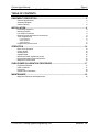
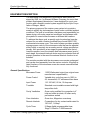
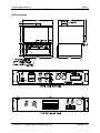
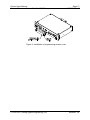
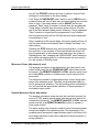
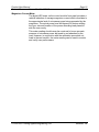
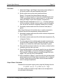
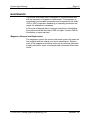
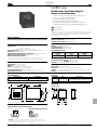
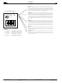
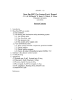
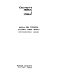
1
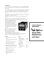
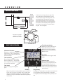
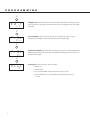
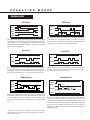
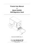
Product User Manual ♦ Custom Microwave Oven Part No. 912112 Document # 930062, Rev. 6 GERLING Gerling Applied Engineering, Inc. P.O. Box 580816 ♦ Modesto, CA 95358 www.2450mhz.com Product User Manual Custom Microwave Oven – Part No. 912112 REV. 1 2 3 4 5 6 REVISION HISTORY DESCRIPTION PROTOTYPE RELEASE Corrected Stage 2 programming procedure Updated schematic Misc. updates Corrected timer setting instructions Changed Stage 2 “Short” timer Page 2 930062, Rev. 6 DATE 21DEC05 12JAN06 27APR06 31OCT06 11MAY07 10JUL07 APPROVAL JFG JFG JFG JFG JFG JFG WARRANTY Products manufactured and sold by Gerling Applied Engineering, Inc. (“GAE”) are warranted to be free of defects in materials and workmanship under normal use and service for a period of twelve (12) months from the date of original shipment. GAE’s obligation under this warranty is limited to repairing or replacing, at GAE’s option, all nonconsumable component parts. Consumable parts are specifically excluded from this warranty and may include, but are not be limited to, magnetrons, fuses, lamps, seals, orings, v-belts, and fluids. All warranty repairs are to be done at GAE’s facility or as otherwise authorized by GAE. All shipping charges for warranty repair or replacement are the purchaser’s responsibility unless otherwise agreed to by GAE. This warranty supercedes all other warranties, expressed or implied. No warranty is given covering the product for any particular purpose other than as covered by the applicable product specifications. GAE assumes no liability in any event for incidental or consequential damages, financial losses, penalties or other losses incurred in conjunction with the use of GAE products. DOCUMENT CONVENTIONS NOTE: Means the reader should take note. Notes contain helpful information, suggestions, or references to other sections, chapters, or documents. CAUTION: Means the reader should be careful. You are doing something that might result in equipment damage or loss of data. WARNING: Means danger. A situation exists that could cause bodily injury or death. All personnel must be aware of the hazards involved with high voltage electrical circuitry and high power microwave devices. 2005-2007 Gerling Applied Engineering, Inc. Modesto, CA Product User Manual Custom Microwave Oven – Part No. 912112 Page 3 930062, Rev. 6 WARNING The microwave oven described in this manual is capable of producing a microwave field that is potentially hazardous to operating personnel. The unit must never be connected or operated in a manner that allows a field in excess of 10 milliwatts per square centimeter to be generated in an area accessible to operating personnel. Contact GAE, Inc. for technical support prior to installation and/or operation of these units if there is any question or concern about microwave leakage. All electrical cable connections must be secure prior to operation. Never operate the microwave oven without a properly rated absorbing load inside the oven cavity. To ensure safe operation and prevent microwave leakage, the equipment must be periodically inspected and maintained as required or recommended. 2005-2007 Gerling Applied Engineering, Inc. Modesto, CA Product User Manual Custom Microwave Oven – Part No. 912112 Page 4 930062, Rev. 6 TABLE OF CONTENTS EQUIPMENT DESCRIPTION.......................................................................................... 5 General Specifications Schematic Diagram Outline Drawing 5 7 8 INSTALLATION .............................................................................................................. 9 Preliminary Inspection Mounting Position Line Power Connection Remote Control and Interlock Connections Timer Programming Pre-Programming Stage 1 Duration Stage 2 Duration Programming Access Cover 9 9 9 9 10 10 11 11 12 OPERATION ................................................................................................................. 14 Basic Oven Operation Control Power Standby Mode Operate Mode Microwave Power Adjustment (Local) Remote Microwave Power Adjustment Magnetron Current Meter 14 14 14 14 15 15 16 OVEN POWER CALIBRATION PROCEDURE ............................................................ 17 Equipment Required Initial Conditions Procedure Output Power Calculation 17 17 18 18 MAINTENANCE ............................................................................................................ 19 Magnetron Removal and Replacement 2005-2007 Gerling Applied Engineering, Inc. 19 Modesto, CA Product User Manual Custom Microwave Oven – Part No. 912112 Page 5 930062, Rev. 6 EQUIPMENT DESCRIPTION The microwave oven described in this manual was custom designed by GAE, Inc. for Sherwin Williams Company for use in their product development laboratories. It was designed for use in conjunction with a humidity control system supplied by the Nyle Corporation of Bangor, Maine. The primary purpose of the custom oven system is to provide a means to quickly dry test samples of paint under controlled ambient conditions. The goal is to maintain consistency and repeatability between drying runs under same test conditions, and between multiple systems in use at either the same or different lab locations. To achieve the above goal, a special control system has been developed for use with a custom modified Sanyo model EM-E1100 commercial microwave oven. This control system provides variable average power control of the microwave oven that can be adjusted either locally or remotely via an analog control voltage provided externally. Also provided is a two-stage programmable timer that allows the operator to set the duration and microwave power level of each stage. An external interlock device may be connected that will prevent operation in the event the external interlock function is not satisfied. The controls provided with the microwave oven remain unchanged and can be used separately from the custom controls. All safety related functions of the microwave oven also remain unmodified and fully functional. General Specifications Microwave Power 11000 Watts rated output (per original oven manufacturer’s specification) Power Control Variable duty cycle from zero to 100% in 4% increments; 417 millisecond time base Input Power 110-120 VAC, 60 Hz, 15 Amp max. Turntable Standard oven turntable covered with hightemp silica cloth Cavity Ventilation Oven cavity modified for connection to 4” inlet and outlet air ducts; All other cavity perforations sealed Oven Interlocks Oven door; Magnetron over-temp Remote Interlock Connections for dry contact switch rated for 120 VAC, 1/4 Amp Cycle Timer 2-Stage digital programmable timer; Stage 1 Duration: 1-9999 seconds 2005-2007 Gerling Applied Engineering, Inc. Modesto, CA Product User Manual Custom Microwave Oven – Part No. 912112 Page 6 930062, Rev. 6 Stage 2 Duration: Selectable between two programmable settings: ”Long” Duration: 0.1-999.9 seconds ”Short” Duration: 1-999 seconds Local Controls Power On/Off (toggle switch) Stage 1 Mw Power Adjust (10-turn dial) Stage 2 Mw Power Adjust (10 turn dial) Stage 2 Long/Short Select (toggle switch) Remote/Local Power Adjust (toggle switch) Mw Start (pushbutton switch) Mw Stop (pushbutton switch) Local Indicators System Ready (Green) Stage 1 On (Red) Stage 2 On (Red) Magnetron Power (Digital display) End of Cycle Buzzer Remote Control 0-10 VDC input for average power control 2005-2007 Gerling Applied Engineering, Inc. Modesto, CA Product User Manual Custom Microwave Oven – Part No. 912112 Page 7 930062, Rev. 6 Schematic Diagram 2005-2007 Gerling Applied Engineering, Inc. Modesto, CA Product User Manual Custom Microwave Oven – Part No. 912112 Page 8 930062, Rev. 6 Outline Drawing 2005-2007 Gerling Applied Engineering, Inc. Modesto, CA Product User Manual Custom Microwave Oven – Part No. 912112 Page 9 930062, Rev. 6 INSTALLATION Preliminary Inspection Upon arrival at the installation site the custom oven system should be thoroughly inspected for damage or wear caused during shipping. Any visible damage to the packaging material or the magnetron head itself should be noted and reported immediately to the shipping company in accordance with standard claims procedures. The following items are supplied with the system: 1. Custom Oven System (microwave oven, control module and cabinet) 2. Fabric covered turntable and support roller ring 3. Original oven user manual 4. Product User Manual (this document) Mounting Position The custom oven system is supplied as an integral assembly consisting of the modified microwave oven, control module control cabinet. It must be mounted upright on a level surface capable of supporting its weight. Sufficient clearance must be provided at the top and rear of the oven to allow adequate ventilation and connection to the inlet and outlet ventilation ducts. Line Power Connection Line power is supplied to the system by connecting the oven power cord (located at the rear of the oven) to a standard 120 VAC grounded outlet receptacle. The circuit supplying voltage to the receptacle must be rated for at least 15 Amps of continuous current draw. Although a 15 Amp fuse is provided inside the oven, the line power supply circuit should also be fused or circuit breaker protected. Remote Control and Interlock Connections Remote power control and interlock connections are made to the 6position terminal block (TB1) located on the rear panel of the control module. WARNING: Disconnect line power before performing the following step to protect against exposure to hazardous voltages. Positions TB1-1 and TB1-2 are to be connected to a dry contact type interlock device rated for 120 VAC, ¼ Amp, that provides a short circuit connection when the interlock function is satisfied. In 2005-2007 Gerling Applied Engineering, Inc. Modesto, CA Product User Manual Custom Microwave Oven – Part No. 912112 Page 10 930062, Rev. 6 the absence of an external interlock device, connect a jumper wire between positions 1 and 2 to enable system operation. For remote control of microwave peak power, connect a 0-10 VDC analog signal between positions TB1-3 and TB1-4 with the positive (+) side connected to TB1-3. Timer Programming The control module includes two multifunction programmable timers. The timer located on the control module front panel (TM1) can be programmed for Stage 1 and Stage 2 “Long” duration, while another timer located inside the control module (TM2) can be programmed for Stage 2 “Short” duration. The operating instructions supplied by the timer manufacturers have been provided as a supplement to this Product User Manual as a reference for user programming. Pre-Programming Since both timers are multifunction programmable, both require programming of the operation mode. Stage 1 Timer Pre-Programming The front panel timer (TM1) has been preprogrammed by GAE for the following program modes: Operating Function: Delay/Interval (provides 2-stage timer functionality) WARNING: The control module circuitry requires the timer to be programmed for the “Delay/Interval” operating function ONLY. Operating the oven system with the timer programmed for a different operating function can result in faulty and possibly unsafe system operation. Time Range: Seconds Decimal Position: 1/10ths (0.0) Timing Direction: Down (timing will decrement from the preset value and change the output state at zero) Power Reset Enable: On (timer is reset upon application of line power) Front Panel Reset Enable: On (timer can be reset by simultaneously pressing E and P keys) Security Level: 0 = Full access 2005-2007 Gerling Applied Engineering, Inc. Modesto, CA Product User Manual Custom Microwave Oven – Part No. 912112 Page 11 930062, Rev. 6 Stage 2 “Short” Timer Pre-Programming The internal timer (TM2) has been preprogrammed by GAE for the following program modes: Operating Function (rotary switch): On-Delay (relay operates at end of timing cycle) Time Base (right-most thumbwheel switch): S (seconds) Stage 1 Duration Use the numeric keys 1 through 4 to adjust the Stage 1 duration from 1 to 9999 seconds. Prior to system operation, the value will be displayed in both lines (large and small numbers) of the timer digital display. Once set, the value will be retained for each consecutive cycle until readjusted by the operator. Stage 2 Duration Stage 2 operation of the system may be preset to one of two operator selectable durations. The “Long” stage 2 duration is determined by the front panel timer (TM1) while the Stage 2 “Short” duration is determined by the timer (TM2) located inside the control module chassis. Stage 2 “Long” Duration Programming Press the “P” button and hold for 3 seconds. This puts the timer into “Program Mode” where it will stay until a) the “P” button is again pressed and held for 3 seconds, or b) there has been no key activity for 60 seconds. Once in Program Mode, press the “P” button once more to enter the Interval Time parameter (“int” appears on the upper line of the LCD display). Use the 1 thru 4 keys to set the value in the range of 0.1 to 999.9 seconds as shown in the lower line of the LCD display. Press and hold the “P” button for 3 seconds to save the value and return the timer to operate mode. Note that the Stage 2 “Long” duration preset value will not be shown on the timer display prior to system operation. Stage 2 “Short” Duration Programming WARNING: Disconnect line power before performing the following step to protect against exposure to hazardous voltages. To gain access to the Stage 2 “Short” duration timer (TM2), slide the control module out of the cabinet and remove the top cover. Located the timer mounted horizontally to the bracket on the chassis bottom (see Figure 1). The Stage 2 “Short” duration timer (TM2) must first be preprogrammed to the “On-Delay” function by setting the rotary switch 2005-2007 Gerling Applied Engineering, Inc. Modesto, CA Product User Manual Custom Microwave Oven – Part No. 912112 Page 12 930062, Rev. 6 on its front panel accordingly. This timer begins counting down at the end of Stage 1 and actuates a relay to terminate Stage 2 upon completion of its programmed delay time. Adjust the three left-most thumbwheel switches to the desired setting (in seconds) for the Stage 2 “Short” duration time-out. For practical reasons, this timer should not be set for a time-out delay greater than the Stage 2 “Long” duration. Figure 1, Control module chassis showing Stage 2 “Short” duration timer. Programming Access Cover A cover is provided that restricts operator access to the front panel cycle timer and microwave power adjust dials to prevent changes to settings during repeated operation cycles. After setting the power adjust dials as described in the following section, the access cover may be attach to the front panel using two #8-32 screws provided with the cover. 2005-2007 Gerling Applied Engineering, Inc. Modesto, CA Product User Manual Custom Microwave Oven – Part No. 912112 Page 13 930062, Rev. 6 Figure 2, Installation of programming access cover. 2005-2007 Gerling Applied Engineering, Inc. Modesto, CA Product User Manual Custom Microwave Oven – Part No. 912112 Page 14 930062, Rev. 6 OPERATION Basic Oven Operation The microwave oven can be operated independently of the custom controls by means of the original oven control panel. The custom controls need not be turned on or operating in order to use the oven in this manner. All safety related functions of the original oven remain fully operational. However, no preprogramming of the original oven controls has been done by the oven manufacturer or GAE. Consult the oven operating instructions supplied by the oven manufacturer (provided with this manual) for detailed operating and programming instructions. NOTE: Operation of the microwave oven independently of the custom controls will not be disabled by opening the external interlock contacts. Control Power Line power is available to the custom control module whenever line power is supplied to the oven and the oven door is closed. Turning on the POWER switch on the control module front panel supplied line power to and enable the control circuitry which is evidenced by the timer display. Unplugging the oven from the line power source, opening its door or turning off the POWER switch will remove line power from and disable the custom control circuitry altogether. Standby Mode Once line power has been supplied to the control circuitry, the READY indicator will turn on if the external interlock device is closed. The system is then in Standby mode and ready to start generating microwave power. Opening the contacts of the external interlock device or pressing the STOP button will return the system to Standby mode and turn off microwave power. Operate Mode Once in Standby mode, the two stage operating cycle can be started by pressing the START button. Microwave energy will then be delivered to the oven cavity at power levels determined by the settings of the POWER ADJUST dials for each stage of operation. Upon pressing the START button the cycle timer display will begin counting down in seconds and the STAGE 1 indicator will be on. After the first stage has counted down the STAGE 1 indicator will 2005-2007 Gerling Applied Engineering, Inc. Modesto, CA Product User Manual Custom Microwave Oven – Part No. 912112 Page 15 930062, Rev. 6 turn off, the STAGE 2 indicator will turn on and the “Interval Time“ will begin to count down on the timer display. If the Stage 2 LONG/SHORT select switch is set to LONG then microwave power will turn off after the cycle timer display has counted down to zero. If the select switch is set to SHORT and the programmed “Short” stage 2 duration is shorter than the programmed “Long” stage 2 duration then microwave power will turn off at the end of the short duration delay period. However, if the programmed “Short” duration is longer than the programmed “Long” duration then microwave power will turn off after the cycle timer display has counted down to zero. After completion of the second stage, microwave power will turn off and the timer will be automatically reset to display the Stage 1 duration setting. Pressing the STOP button at any time during operation, or opening the oven door or the contacts of the external interlock device, will stop the generation of microwave power and return the system to Standby mode. Also, changing the LONG/SHORT select switch position while microwave power is on will terminate the cycle and return the system to Standby mode. Microwave Power Adjustment (Local) The average microwave power delivered by the oven can be controlled locally using the two POWER ADJUST dials located on the front panel. The REMOTE ANALOG / LOCAL selector switch must be in the LOCAL position to enable power control using the front panel dials. Two dials are provided for independent power control during each stage of the operating cycle. The dials can be adjusted either before or during cycle operation. The dial readings when multiplied by ten (x10) provide an approximate indication of the percentage of microwave output power. Remote Microwave Power Adjustment The average microwave power can also be controlled remotely using a 0-10 VDC analog control signal (see the previous section for connection information). The REMOTE ANALOG / LOCAL selector switch must be in the REMOTE ANALOG position to enable remote power control. The same analog control signal is used to control microwave power during both stages of the operating cycle. The percentage of microwave power generated is approximately equal to ten times (x10) the voltage delivered. Power can be adjusted at any time before or during operation. 2005-2007 Gerling Applied Engineering, Inc. Modesto, CA Product User Manual Custom Microwave Oven – Part No. 912112 Page 16 930062, Rev. 6 Magnetron Current Meter The digital LED meter on the control module front panel provides a relative indication of average magnetron current which correlates to the approximate level of microwave power being generated by the magnetron. The actual power level will depend on factors relating the type, size and location of the power absorbing load placed inside the oven cavity. This meter reading should never be construed to be an accurate measure of microwave power delivered to and absorbed by the load. However, in conjunction with the calibration procedure outlined in the next section, the meter reading can be used to monitor and verify oven performance. 2005-2007 Gerling Applied Engineering, Inc. Modesto, CA Product User Manual Custom Microwave Oven – Part No. 912112 Page 17 930062, Rev. 6 OVEN POWER CALIBRATION PROCEDURE The procedure outlined in this section can be used to correlate the MAGNETRON CURRENT meter reading with actual microwave power delivered by the oven for a specific load. It is derived from the international standard IEC 60705 (3rd Edition, 1999-04) used worldwide by microwave oven manufacturers for performance measurement. NOTE: This procedure utilizes a standardized water load for calibration. As with any microwave oven, the actual power generated may vary with different load types, sizes and locations within the oven cavity. However, the performance variation between two different loads will remain constant as long as both loads remain unchanged. The procedure involves heating the water from a starting temperature below ambient temperature to approximately ambient temperature using energy from the microwave oven. This enables a reasonably accurate compensation for heat loss to the container. The procedure may be performed at any microwave power setting as may be required for calibration of normal operation. Equipment Required • Cylindrical container made of borosilicate glass (Pyrex) with outside diameter of approximately 190 mm, height of approximately 90 mm and maximum thickness of 3 mm • Potable (tap) water, approximately 1000 grams • Thermocouple probe thermometer capable of accurately measuring the temperature of the water • IR optopyrometer capable of accurately measuring the temperature of the empty container • Scale capable of accurately measuring the weight of the container, both empty and filled with water • Line voltage to be within the range per the oven specifications and within +/-1 % of the voltage to be supplied during normal operation. • Ambient temperature to be 20 °C +/-5 °C. • The temperature of the microwave oven power supply components to be within +/-5 °C of ambient. This condition can usually be met by not operating the oven for a few hours. External forced air cooling may be used to shorten this time. Initial Conditions 2005-2007 Gerling Applied Engineering, Inc. Modesto, CA Product User Manual Custom Microwave Oven – Part No. 912112 Page 18 930062, Rev. 6 Procedure 1. Adjust both Stage 1 and Stage 2 microwave power settings on the control panel to the same desired power level. 2. Set the cycle timer on the control panel as follows: Stage 1: 2 seconds (this allows filament warm-up) Stage 2: A value (t) equal to 52 seconds multiplied by the ratio of full output power to the set output power (i.e. for half power setting the Stage 2 cycle time should be 104 seconds). 3. Adjust the water temperature to 10 °C +/- 1 °C before putting it into the container. Ice chips may be used to lower the temperature, but the ice should be completely melted prior to heating. 4. Accurately measure and record the container mass (mc) in grams. Note: Steps 5 through 10 should be done in rapid succession to minimize heat loss and temperature measurement error. 5. Accurately measure and record the initial container temperature (T0) in degrees Celsius. 6. Accurately measure and record the initial water temperature (T1) in degrees Celsius. 7. Pour the water into the container and accurately measure and record the filled container weight. Subtract the empty container weight (mc) to obtain the actual water weight (mw) in grams. 8. Place the filled container inside the oven cavity, centered on the turntable, and close the oven door. 9. Press the Start button on the control panel to turn on microwave power. During Stage 2, record the reading of the Magnetron Current meter. Allow the system to operate through both cycle stages. The oven will turn off automatically. 10. Upon completion of Stage 2, open the oven door and accurately measure and record the final water temperature (T2) in degrees Celsius. Gentle stirring will provide a more accurate measurement of average temperature. Output Power Calculation Calculate the microwave output power using the following formula: P = [4.187 ∗ mw (T2 – T1) + 0.55 ∗ mc (T2 – T0)]/t The meter reading recorded in step 9 above now corresponds to the calculated output power. 2005-2007 Gerling Applied Engineering, Inc. Modesto, CA Product User Manual Custom Microwave Oven – Part No. 912112 Page 19 930062, Rev. 6 MAINTENANCE The custom microwave oven is designed to be maintenance free with the exception of magnetron replacement. The magnetron is considered a consumable component and is expected to fail within 1000 to 3000 of operation depending on operating conditions and usage. No calibration is necessary. In the event of damage due to improper operation or mishandling, the system should be returned to GAE for repair. Contact GAE for information on repair services. Magnetron Removal and Replacement The magnetron used in the custom microwave oven is the same as that supplied with the original oven by its manufacturer. Replacement of the magnetron should be done only by technical personnel properly trained for repair of residential and commercial microwave ovens. 2005-2007 Gerling Applied Engineering, Inc. Modesto, CA Introduction An excellent value in its class, the B856 features a compact 1/16 DIN package, the precision of digital setting, versatile functionality, and a straightforward button-perdigit interface. It can be easily programmed to perform any standard timing operation: On-Delay, OffDelay, Interval 1, Interval 2, or Repeat Cycle. A unique On-Delay /Interval Mode can in many cases perform the function of two separate timers. Output is via DPDT relay contacts. Five selectable time ranges, and a programmable decimal point provide preset times ranging from .01 seconds to 9999 hours. An available model's output features separate timed and instantaneous SPDT contacts. Simplicity of operation is maintained while still providing a high level of functionality. All programming is done through the front panel, with an intuitive button-per-digit keypad that makes entry of preset times quick and easy. A crisp dual line LCD display lets the operator readily view elapsed or remaining cycle time as well as the preset value. Prominent annunciators indicate information such as the time range and the status of the input and outputs. Reliability is a key feature of the B856. IEC Level 4 noise immunity ensures flawless operation in harsh electrical environments, while its IEC IP65 enclosure rating allows use in washdown conditions. Eagle Signal brand Series B856 Multifunction LCD Timer Wiring via an industry standard 11 pin socket and a power supply that can accept 24 - 240 VAC or 24 VDC vastly simplify setup. Features • Field programmable choice of 6 operating modes • 5 selectable time ranges with resolution down to 0.01 seconds • High Contrast LCD display indicates both process time and preset value • Simple button per digit interface • Programmable security levels prevent unauthorized setpoint or program changes • Universal Power Supply (24 - 240 VAC, 24 VDC) • External Start and Reset Inputs • UL and CUL recognized, CE marked • IEC IP65 rated front panel • Model with Instantaneous contacts also available Index Overview Panel Mounting Wiring Connections Front Panel Operation Programming Program Mode Operating Modes Timing Diagrams General Specifications Ordering Information Warranty Technical Manual 702070-0001 page 2 page 2 page 2 page 3-4 page 5 page 8 page 8 page 8 O V E R V I E W INSTALLATION & WIRING 8mm Socket To wire the unit, an 11 pin socket is required. The unit can then either be DIN rail mounted or panel mounted using the supplied mounting bracket. For panel mounting, place the unit in the cutout, then slide the bracket forward over the rear of the unit so that the tabs catch in the grooves on the housing and the bracket is as far forward as possible. Tighten the panel mount screws until there is a snug fit against the panel. Do not overtighten. 48mm 66mm 81mm Reset Start 6 5 For the -511 version, Pins 1, 3, 4 are the instantaneous contacts 7 4 8 3 9 2 1 11 10 Power FRONT PANEL OPERATION I/O Status Indicators Illuminates to display when an input or output is active: "IN' for the start input, "OUT" for the timed output, and "RST" for the external reset signal. Time Indicators The word "Timing" flashes when a timing function is taking place. The applicable arrow also lights to indicate if the display is set to time up or time down. EAGLE SIGNAL 1234 H M IN OUT RST Timing Set Value Settable value used to trigger the timed output. 1234 4 3 E Time Value Indicates the elapsed/remaining time to preset. Edit Key Many of the parameters in Program Mode require selection of a specific choice as opposed to a numeric value. The Edit key is used to scroll through the available choices. In Operation mode, the Edit key can be pressed simultaneously with the Program key to reset the timer. 2 H M S 2 Time Range Indicator Illuminates to show the time base: H for hours, M for minutes, S for seconds. Multiple indicators will be illuminated when the time base is Hours:Minutes or Minutes:Seconds. 1 P Numeric Keys Each of the number keys is used to increment or decrement the value of the corresponding digit of the preset or a parameter value (increments if unit is set in time up mode and decrements if set in time down mode). Program Key Pressing the key continuously for 3 seconds moves the unit in and out of Program mode. Once in Program mode, pressing and releasing the key will scroll the display from one parameter to the next. P R O G R A M M I N G PROGRAM MODE • Enter the Program Mode by holding down the "P" key for 3 seconds • Press the "P" key to move the top display from one parameter to the next • Press the "E" key to scroll the bottom display through the available choices for that parameter • While in Program Mode the unit will stop timing, and the output will retain its last state. The new settings will only become effective after returning to Operation Mode by holding down the "P" key for 3 seconds P For 3 Seconds F u n c O n d L P 1 S t O n Operating Function: Determines how outputs will operate in relation to the set value. Choices are: • On-Delay (OndL) • Off Delay (OFdL) • Interval 1 (int1) • Interval 2 (int2) • Delay/Interval (dint) • Repeat Cycle (CYCL) See Appendix A for timing charts. First Operation: Determines whether the Repeat Cycle will start with an On or an Off Operation Note: This parameter will only appear if Repeat Cycle is chosen as the Operating Function P i n t 1 . 0 S P t r n G S P d E c P 0S Interval Time: Sets the amount of time the output will be active after the On-Delay function has timed out. Use the 1 through 4 keys to set the value in a range from 0.1 to 999.9 seconds. Note: This parameter will only appear if Delay/Interval is chosen as the Operating Function Time Range: Sets the unit of measure for the time values that will be shown on the display in Operation Mode. Choices are: • Seconds • Minutes • Hours • Minutes:Seconds • Hours:Minutes Decimal Position: Sets the decimal position for the time display. Choices are: no decimal point (0), 1/10ths position (0.0), or Hundredths position (0.00). The time range selected in the previous parameter will remain illuminated for reference. Note: This parameter will not appear if Minutes:Seconds or Hours:Minutes is selected as the time range 3 P R O G R A M M I N G P t d i r u P Timing Direction: Determines whether the time value will increment from zero and change the state of the output at the set value (uP) or decrement from the set value and change the state of the output at zero (dn). P P r S t O Power Reset Enable: After a loss of power, the unit can be programmed to either reset upon reapplication of power (On) or continue from the point of power interruption (Off). n P F r S t O n Front Panel Reset Enable: When active (On), the timing operation can be reset in Operation Mode by simultaneously pressing the "E" and "P" keys. If inactive (Off), the timing operation can only be reset through the remote input. P S L u L 0 Security Level: 4 different levels of security are available: 0 = Full Access 1 = SP Locked Out 2 = Access to Program Mode only by holding the "P" key for 8 seconds 3 = SP Locked Out and access to Program Mode only by holding the "P" key for 8 seconds 4 O P E R A T I N G M O D E S TIMING DIAGRAMS Off-Delay On-Delay Power Power Start Output Start T Reset Instant. Output T Output Timing begins on the leading edge of the start input. The output will activate at the completion of the preset time (T) and will remain active until the reset signal is applied or power is interrupted.* The instantaneous output will activate upon the start signal and will remain active until the reset signal is applied or power is interrupted.* The output is activated at the leading edge of the start signal. Timing begins on the trailing edge. The output will remain active until the preset time (T) has elapsed or power is interrupted.* Reapplying the start signal before T has elapsed will reset the time value. The reset input is not used. Interval 1 Interval 2 Power Power Start Start Output T T T Output T T On the leading of the start input, the output is activated and timing begins. The output will remain active until the preset time (T) has elapsed or power is interrupted.* Removal of the start signal will also cause the output to be deactivated and the time value to be reset. The reset input is not used. On the leading of the start input, the output is activated and timing begins. The output will remain active until the preset time (T) has elapsed or power is interrupted.* The reset input is not used. Repeat Cycle Delay/Interval Power Power Start Repeat Cycle Start Output Output T T T Reset Reset Power Start Output T1 T2 Reset Timing begins on the leading edge of the start signal. A cycle is initiated where the output will be OFF for the preset time (T), then ON for the preset time. This cycle will continue until a reset signal is applied or power is interrupted.* The unit can also be programmed for the timing sequence to begin with an ON cycle. * The Power Reset parameter in Program Mode can be set so that a timing sequence will not be reset upon power interruption but instead continue on when power is restored. The delay cycle begins upon application of the start signal. The output will activate at the completion of the preset time (T1). Upon activation of the output, the Interval cycle will begin. The output will be deactivated at the end of the Interval time (T2). T1 is the primary preset value and is set in Operation Mode. T2 is set in Program Mode in a range from 0.1 to 999.9 seconds. The timing sequence and output can also be reset through the reset input or interruption of power.* 5 N O T E S DANAHER CONTROLS has representatives and distributors located in major cities within the United States and throughout the world. For information about the distributor or sales office nearest you, contact our customer service department: 6 Customer Service Internet Presence call Toll Free 800.873.8731 or 847.662.2666 E-Mail: dancon@dancon.com Worldwide Web: http://www.dancon.com Veeder-Root Dynapar Eagle Signal N O T E S DANAHER CONTROLS has representatives and distributors located in major cities within the United States and throughout the world. For information about the distributor or sales office nearest you, contact our customer service department: Customer Service Internet Presence call Toll Free 800.873.8731 or 847.662.2666 E-Mail: dancon@dancon.com Worldwide Web: http://www.dancon.com Veeder-Root Dynapar Eagle Signal 7 G E N E R A L Operation Supply Voltage: Power Consumption: Time Ranges: ORDERING INFORMATION SPECIFICATIONS Inputs Start: Reset: NPN or Dry Contact NPN or Dry Contact Resolution: Operating Modes: Outputs Timed (B856-500): Timed (B856-511): Instantaneous (B856 -511): Activation Time: Physical Dimensions: Mounting Wiring Connection Repeat Accuracy: Electrical Service Life: Mechanical Service Life: Weight: DPDT - 5 amp SPDT - 5 amp SPDT - 5 amp 15 msec. max. 48mm x 48mm, 81mm deep Panel Mounting 45 x 45 cutout, or DIN rail Via 11 pin plug in socket Environmental Front Panel Rating: Operating Temperature: Storage Temperature: Humidity: Approvals: 24 - 240 VAC 50/60Hz, or 24 VDC 50 VA @ 240 VAC Hours, Minutes, Seconds, Hours:Minutes, Minutes:Seconds Settable for XXXX or XX.XX for Hours, Minutes and Seconds ranges On Delay, Off Delay, Interval 1, Interval 2, Repeat, Delay/Interval + 0.03% 100,000 cycles at full load 10 million cycles at min. load 100 grams (3.5 ounces) IEC IP65 B856-500: 0° to 60° C (32° to 140° F) B856-511: 0° to 50° C (32° to 122° F) -40° to 90° C (-40° to 194° F) 5% to 95% RH non-condensing UL, CUL recognized; CE certified ORDERING INFORMATION Description Model # Description Model # Multifunction Timer, 24 - 240 VAC, 24 VDC B856-500 11 Pin Socket 60SR3P06 Timer w/Instant Cont, 24 - 240 VAC, 24 VDC B856-511 11 Pin Socket - Outward Facing Terminals PBT-03172 WARRANTY Standard B856 products manufactured by the Company are warranted to be free from defects in workmanship and material for a period of two years from the date of shipment, and products which are defective in workmanship or material will be repaired or replaced, at the option of the Company, at no charge to the Buyer. Final determination as to whether a product is actually defective rests with the Company. The obligation of the Company hereunder shall be limited solely to repair and replacement of products that fall within the foregoing limitations, and shall be conditioned upon receipt by the Company of written notice of any alleged defects or deficiency promptly after discovery within the warranty period, and in the case of components or units purchased by the Company, the obligation of the Company shall not exceed the settlement that the Company is able to obtain from the supplier thereof. No products shall be returned to the Company without its prior consent. Printed in U.S.A. #702070-0001 February 1998 Revision A 8 Products which the Company consents to have returned shall be shipped F.O.B. the Company's factory. The Company cannot assume responsibility or accept invoices for unauthorized repairs to its components, even though defective. The life of the products of the Company depends, to a large extent, upon the type of usage thereof, and THE COMPANY MAKES NO WARRANTY AS TO FITNESS OF ITS PRODUCTS FOR SPECIFIC APPLICATIONS BY THE BUYER NOR AS TO PERIOD OF SERVICE UNLESS THE COMPANY SPECIFICALLY AGREES OTHERWISE IN WRITING AFTER THE PROPOSED USAGE HAS BEEN MADE KNOWN TO IT. THE FOREGOING WARRANTY IS EXCLUSIVE AND IN LIEU OF ALL OTHER WARRANTIES EXPRESSED OR IMPLIED, INCLUDING, BUT NOT LIMITED TO ANY WARRANTY OF MERCHANTABILITY OR OF FITNESS FOR A PARTICULAR PURPOSE. Danaher Controls 1675 Delany Road Gurnee, IL 60031–1282 Phone: 847.662.2666 Fax: 847.662.6633 Email: dancon@dancon.com Catalog 1308242 Issued 3-03 P&B CNM5 series Multifunction Time Delay Relay For Plug-In or Panel Mounting • • • • • • Five timing functions selectable via rotary switch 0.1 sec. to 9,990 hr. timing range Fixed input type (120VAC ± 15%) 10A output relay with DPDT contacts 1/16 DIN style enclosure with 11-pin plug-in base Thumbwheel switches for programming delay time File E22575 File LR15734 Users should thoroughly review the technical data before selecting a product part number. It is recommended that user also seek out the pertinent approvals files of the agencies/laboratories and review them to ensure the product meets the requirements for a given application. Timing Functions Initial Dielectric Strength See the following page for a complete description of timing functions. Between Output Poles: 1,500V rms, 60 Hz. Between Input and Output: 1,500V rms, 60Hz. Input Data @ 25°C Timing Specifications Timing Ranges: 0.1 to 99.9 / 1 to 999 sec.; 0.1 to 99.9 / 1 to 999 min.; 0.1 to 99.9 / 1 to 999 / 10 to 9,990 hr. Timing Adjustment: Digital adjustment via thumbwheel switches. Tolerance: ±0.05% ± 0.04 sec.* Repeatability (Including first cycle of operation.): < ± 0.05% ± 0.04 sec.* Reset Time (power interruption): 45 ms, typ.; 60 ms, max. Minimum Pulse Width, Control: 50 ms. * Timing is synchronized with input voltage frequency. Accuracy is dependent on input voltage frequency. Tolerance shows maximum variation from utility companies. Contact Data @ 25°C Arrangement: 2 Form C (DPDT). Material: Silver-cadmium oxide alloy. Rating: 10A @ 30VDC or 277VAC, resistive; 1/2 HP @ 250VAC; 1/3 HP @ 120VAC. Expected Mechanical Life: 10 million operations. Expected Electrical Life: 100,000 operations, min., at rated load. Voltage: 120VAC ± 15%, 60 Hz. Power Requirement: 3VA @ 120VAC. Transient Protection: 13 Joule MOV. Input Voltage & Limits Nominal Voltage Minimum Voltage Maximum Voltage 120VAC 102VAC 138VAC Environmental Data Temperature Range: Storage: -40°C to +85°C. Operating: -10°C to +55°C. Humidity: 85% relative humidity, non-condensing. Mechanical Data Termination: 11-pin octal style plug. Enclosure: Black plastic 1/16 DIN (48mm x 48mm) case. Sockets: Fits either 27E123 or 27E892 (snap-on) screw terminal sockets. Weight: 4.3 oz. (122g) approximate. Ordering Information – Authorized distributors are more likely to stock boldface items listed below. Time Delay Relay Accessory Input Voltage Part Number 120VAC CNM5 Outline Dimensions Part Number Name Description SSA-24C667 Mounting Clip Ratchet-fit clip slides onto CNM5 from behind to secure CNM5 in panel mount applications. Mounting Clip Dimensions 1.88 (47.8) .32 (8.1) SSA-24C667 2.83 (71.9) Mounting Clip 1.88 (47.8) 1.76 (44.7) 3 1 2 S 3.15 (80.0) .560 (14.2) .64 (16.3) Fits 1.77 x 1.77 (45 x 45) panel cutout. Wiring Diagrams (Bottom Views) 2.283 1.970 (58.0) (50.0) 2.047 (52.0) .591 (15.0) 1.654 (42.0) 1.890 (48.0) (pins numbered clockwise from keyway) EXTERNAL CONTROL SWITCH** CONTROL 1 11 INPUT Optional Solid State Input Interface 1 11 INPUT **Important: A dry circuit switch is recommended. A "dry circuit" switch is one rated to reliably switch currents of less than 50mA. Use of a switch rated for other than dry circuit may result in failure of the time delay relay to function properly. Dimensions are shown for reference purposes only. Dimensions are in inches over (millimeters) unless otherwise specified. Specifications and availability subject to change. www.tycoelectronics.com Technical support: 1215 Refer to inside back cover. Catalog 1308242 Issued 3-03 P&B Timer Function Descriptions Repeat: Output relay is turned on at end of programmed time interval which is started by application of input power. Relay stays on for equal time interval, then turns off and cycle is repeated on a free-running basis with equal on and off times until terminated by removal of input power. LED is flashing when output relay is off and on continuously when the relay is on. Applying CONTROL input during timing will have no effect on timing or the state of the relay. LED to show time status. See functional explanation for details. One Shot: Output relay is turned on by applying CONTROL input with input voltage present or application of input voltage with the CONTROL input on. Immediately upon either, timing is initiated with the output relay turning off at the completion of the selected time interval. Applying CONTROL input after time out will reset the timer, turn on the output relay and initiate another time interval. LED is on continuously when output relay is off and flashes when the relay is on. Applying CONTROL input during timing will have no effect on timing or the state of the relay. REPEAT ONE SHOT OFF DELAY INTERVAL ON DELAY 3 1 2 TIME SET 000 TO 999 Off Delay: Output relay is turned on by applying CONTROL input with input voltage present or application of input voltage with the CONTROL input on. The time interval will be started by removing the CONTROL input with the output relay turning off at completion of the time interval. Reapplying the CONTROL during timing will reset the time to zero and inhibit timing until removed. LED is off when CONTROL input is on, flashing during timing and on continuously when the output relay is off. S TIME BASE Interval: Output relay is turned on for a programmed time interval by applying input voltage. LED flashes when output relay is on and is on continuously when the output relay is off. Applying CONTROL input will have no effect on timing or the state of the relay. Time Base: .1 S S .1 M M .1 H H 10 H = = = = = = = 1/10 Seconds Seconds 1/10 Minutes Minutes 1/10 Hours Hours 10 Hours Dimensions are shown for 1216 reference purposes only. Timing Range 0.1 to 99.9 Seconds Timing Range 1 to 999 Seconds Timing Range 0.1 to 99.9 Minutes Timing Range 1 to 999 Minutes Timing Range 0.1 to 99.9 Hours Timing Range 1 to 999 Hours Timing Range 10 to 9990 Hours Dimensions are in inches over (millimeters) unless otherwise specified. On Delay: Output relay is off for a programmed time interval which is started by applying input voltage. LED flashes when output relay is off and is on continuously when the output relay is on. Applying CONTROL input will have no effect on timing or the state of the relay. Specifications and availability subject to change. www.tycoelectronics.com Technical support: Refer to inside back cover.