Download Users` manual


Transcript
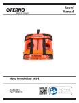
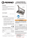
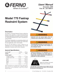
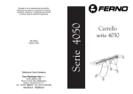
Users’ manual
Device for craniocaudal immobilization
and extrication XT
July 2013
Pub. No. MU-086-C
Read this Manual
carefully and Keep it
for Future Reference
XT extrication device
Ferno Technical Support
Customer service and product support are important aspects of
every Ferno product. Before contacting us, have the product serial
number available and include it in all written communications. For
technical support questions, contact Ferno Washington Italia s.r.l.:
Telephone (toll free)
800.501.711
Fax0516861508
E-mailinfo@ferno.it
Ferno Customer Relations
To request support or for additional information, contact Ferno
Washington Italia s.r.l. Customer Service:
MANUFACTURER
Ferno Washington Italia s.r.l., Via Benedetto Zallone 26
40066 - Pieve di Cento (BO) - ITALIA
Telephone (toll free)
800.501.711
Telephone 0516860028
Fax0516861508
Internet
www.ferno.it
USERS’ MANUAL
To request additional free user manuals
contact Ferno Washington Italia Customer
Service.
1
2
3
4
Limitation of Liability
This manual contains general instructions for the use and care
of this product. These instructions do not include all possible
applications and operations. Correct and safe product use is the
sole responsibility of the user. Safety information is included
as a service to the user and only guarantees the minimum level
necessary to avoid accidents involving operators and patients.
Any other safety measure implemented by the user must take the
applicable regulations into account. Operators must be trained
before using this product. Keep the manual for future reference.
Include the manual with the product in the event of transfer to a
new user. Additional free copies are available upon request from
Ferno Washington Italia Customer Service.
Serial Number
2
160 kg
352 lb
XT serial number _________________________
Location: Lower side of the main label.
Proprietary Notice
The full or partial reproduction of this manual is prohibited if not
specifically authorized by Ferno Washington Italia s.r.l.
The information disclosed in this manual is the property of Ferno
Washington Italia s.r.l. - Via Benedetto Zallone 26, 40066 Pieve
di Cento (BO). Ferno-Washington, Inc. reserves all patent rights,
proprietary design rights, manufacturing rights, reproduction use
rights, and sales use rights thereto, and to any article disclosed
therein except to the extent those rights are expressly granted to
others or where not applicable to vendor proprietary parts.
Limited Warranty Statement
The products sold by Ferno are covered by a 24 month warranty
against manufacturing defects. The complete version of the liability
and warranty terms and conditions can be found in the Warranty
section, page 21.
© Copyright Ferno Washington Italia s.r.l. All rights reserved.
2
© Ferno Washington Italia MU-086-C July 2013
XT extrication device
TABLE OF CONTENTS
Section/ParagraphPage
Section/ParagraphPage
Ferno Customer Relations_______________________ 2
Ferno Technical Support________________________ 2
1 - Safety information____________________________ 4
1.1Warning_________________________________ 4
1.2Important________________________________ 4
1.3 Bloodborne disease notice__________________ 4
1.4 Load capacity____________________________ 4
1.5 Accessory compatibility____________________ 4
1.6 Symbol Glossary__________________________ 5
1.7 Information and safety labels________________ 5
2 - operator skills and training____________________ 6
2.1Skills___________________________________ 6
2.2Training_________________________________ 6
3 - The extrication device_________________________ 6
3.1Description______________________________ 6
3.2 CE Compliance___________________________ 6
3.3 Components (Extrication Device)_____________ 7
3.4 General technical specifications______________ 8
4 - Extrication device configuration________________ 9
4.1 Strap configurations_______________________ 9
4.2 Applying the QHI (Quick Head Immobilizer)__ 11
4.3 Applying the head immobilizer triangle ______ 12
4.4 Applying the red neck strap ________________ 12
5 - Using the extrication device___________________ 13
5.1 Before placing the extrication device in service_ 13
5.2 General Guidelines for Use_________________ 13
5.3 Rapid Extrication________________________ 14
5.4 Precautionary extrication__________________ 15
5.5 Adapting for a pediatric patient_____________ 17
6 - Maintenance________________________________ 18
6.1 Scheduled maintenance____________________ 18
6.2Disinfection_____________________________ 18
6.3Cleaning_______________________________ 18
6.4Inspection______________________________ 18
6.5Storage________________________________ 19
7 - Accessories_________________________________ 20
7.1 XT extrication device accessories____________ 20
8 - Technical support service_____________________ 20
8.1 Customer Technical Support________________ 20
9- Warranty __________________________________ 21
9.1 Warranty conditions______________________ 21
9.2 Limitation of liability_____________________ 21
9.3 Warranty requests________________________ 22
9.4Claims_________________________________ 22
9.5 Return authorization______________________ 22
Training record________________________________ 23
Maintenance record____________________________ 24
© Ferno Washington Italia MU-086-C July 2013
3
Safety information
XT extrication device
1 - SAFETY INFORMATION
Read this user manual carefully. It is an integral part of the
device and must always be kept within reach. The following
points must be observed for your own personal safety and
for the safety of the patients:
– Inspect the device before each use to make sure there are
no signs of wear, damage and/or malfunctions. Refer to the
Inspection section, page 18.
– In order to prevent infections and/or bacterial contamination,
follow directions contained in the Disinfection and Cleaning
paragraphs, page 18.
WARNING
Unauthorized repairs performed by technicians not authorized
by Ferno W. Italia will void any type of warranty and could make
any operation with the extrication device dangerous.
Non-original spare parts and inadequate maintenance can
cause damage and/or injuries. Use only original Ferno spare
parts and contact the Ferno W. Italia service department.
1.2Important
Important notices provide important information
about the use and/or maintenance of the device.
1.1Warning
The warning notices indicate potentially hazardous situations
that, if underestimated, can cause accidents, damage and/or
injuries.
Important
1.3 Bloodborne disease notice
WARNING
Untrained users could injure themselves and/or cause damage and/
or injuries. Only permit trained personnel to use the XT extrication
device.
Improper use of the extrication device can cause damage and/or
injuries. Use the XT extrication device as described in this manual.
Unauthorized changes to the XT extrication device can cause serious
damage, injuries and/or unforeseeable operative problems. Do not
change or alter the extrication device in any manner.
Any damage to the extrication device components or to the entire
system could alter its performance and its safety. Inspect the XT
extrication device frequently and in particular before and after
every use. Make sure that the extrication device cannot be used if
there are signs of wear or damage.
An unattended patient can be injured. Never leave a patient bound
to the extrication device unattended. Stay with the patient at all
times during the rescue operations.
Incorrect use of the straps can cause the patient to fall and be
injured. Always use the restraint straps for the patient as instructed
in this manual.
Improper use of the extrication device can cause injury. Use the
extrication device only as described in this manual.
Untrained assistants can cause damage and/or injuries or injure
themselves. Do not let untrained assistants prepare the extrication
device. Use caution when using the device and coordinating the
helpers.
Improper maintenance can cause serious accidents and/or damage.
Perform the maintenance as described in this user manual.
Attaching improper or unauthorized devices can cause accidents,
damage and/or injuries. Only use devices that are approved and
authorized by Ferno W. Italia.
4
To reduce the risk of exposure to infective bloodborne
diseases, such as HIV-1 or hepatitis, carefully follow the
disinfection and cleaning instructions contained in this
manual.
1.4 Load capacity
Do not exceed the load capacity for the XT extrication
device. Refer to the General technical specifications
paragraph, page 8.
1.5 Accessory compatibility
Use only accessories that have been approved and authorized
by Ferno. The XT extrication device can be used in
combination with the following devices: QHI (Quick Head
Immobilizer), head immobilizer triangle (code 038245211),
red neck strap (code 25-0601-002) and restraint system
(code 25-0500-001).
The XT extrication device has been tested with the following
accessories:
– QHI Quick Head Immobilizer
– WizLoc cervical collar
– Head immobilizer triangle
Any other combination is not compatible with the
specifications and the instructions provided in this manual.
Ferno Washington Italia shall not be liable for any damage
to users or third parties caused by the improper use of the
XT extrication device.
© Ferno Washington Italia MU-086-C July 2013
Safety information
XT extrication device
1.6 Symbol Glossary
The symbols defined below are used on the extrication device and/or in this manual.
2
160 kg
352 lb
Read the user manual
carefully
The extrication device must
be used by at least two
trained operators
Do Not Pressure Wash
QR code
Load capacity
The product complies
with the Standards of
the European Union
1.7 Information and safety labels
The information and safety labels provide important information of which the user must be aware.
Read and follow the instructions on the labels. Immediately replace worn or damaged labels. Contact Ferno Washington Italy
Customer Service to request new labels (page 2). The label shown below is applied on the extrication device.
1
2
3
4
Serial Number
2
160 kg
352 lb
Main label
© Ferno Washington Italia MU-086-C July 2013
5
The extrication device
XT extrication device
2 - OPERATOR SKILLS AND TRAINING
2.1Skills
●
Operators using the extrication device must:
● have a working knowledge of emergency patient
handling procedures.
● have suitable skills to assist the patient.
2.2Training
The users are required to:
● carefully read and understand all the information
provided in this manual.
● follow a training program on the use of the extrication
device.
● practice with the extrication device before using it in
real situations with patients.
record the training sessions. A sample training record
sheet is shown on page 23.
WARNING
Untrained users could injure themselves and/or
cause damage and/or injuries. Only permit trained
and qualified personnel to use the XT extrication
device.
Important
The operators must be able to ensure their own safety and the
safety of patients while using the extrication device. They must
be able to evaluate the number of assistants required to handle
the patient according to the applicable regulations.
3 - THE EXTRICATION DEVICE
3.1Description
The XT extrication device (referred to also as the “extrication
device” in this manual) was developed for the craniocaudal
immobilization and extrication of trauma and non-trauma
patients.
●
A minimum of two trained and qualified operators are
necessary for using the device. A third operator may be
required according to local protocols, and additional help
may be required when handling heavy patients.
●
The extrication device has a system of 4 adjustable straps in
order to correctly immobilize the patient to the extrication
device. The upper chest straps must be applied in a "crisscross" configuration. The lower leg straps must be applied in
a same-side configuration.
●
●
●
●
●
●
●
●
●
3.2 CE Compliance
MEDICAL DEVICE DIRECTIVE
Ferno products comply with the requirements of European
Directive 93/42/EEC concerning medical devices.
The extrication device belongs to Class I.
6
●
●
●
EXTRICATION DEVICE FEATURES
Upper chest straps, yellow and red (2)
Lower leg straps, black and green (2)
The chest straps (yellow and red) have integrated lifting
and carrying handles (4)
Strap fixing holes (15)
Lateral ergonomic grip handles (2)
QHI (Quick Head Immobilizer)
Neoprene head immobilizer
Red neoprene neck strap
SUPPLIED ACCESSORIES KIT XT COMPLETE-B
QHI Quick Head Immobilizer (1 provided)
Head immobilizer triangle (1 provided)
Red neck strap (1 provided in a convenient bag)
Straps (2 chest and 2 leg provided)
Carrying and storage case (1 provided)
User manual
WARNING
Improper use of the extrication device can cause
damage and/or injuries. Use the extrication device
as described in this manual.
© Ferno Washington Italia MU-086-C July 2013
The extrication device
XT extrication device
3.3 Components (Extrication Device)
Neoprene head immobilizer
triangle
Red neck strap
with bag
QHI Quick Head
Immobilizer
Upper yellow
chest strap
Upper red
chest strap
Lower green
leg strap
Lower black
leg strap
Lifting and carrying handles
(4)
FRONT VIEW
USERS’ MANUAL
Contact Ferno Washington Italia
Customer Service (page 2) to request
additional free copies of the user
manual.
© Ferno Washington Italia MU-086-C July 2013
7
The extrication device
XT extrication device
3.4 General technical specifications
Ferno reserves the right to change the specifications without
notice. For additional information, contact Ferno Customer
Service (page 2).
Material
XT board
QHI head immobilizer
Straps
Buckles
Head immobilizer triangle and neck strap
Length
Width
Thickness
Weight
Load capacity
Maximum load per handle composite
polyurethane
nylon
plastic
neoprene
830 mm
300 mm
6 mm
2 kg
160 kg
40 kg
Load capacity
160 kg
352 lb
8
WARNING
Untrained users could injure themselves and/or
cause damage and/or injuries. Only permit trained
and qualified personnel to use the XT extrication
device.
WARNING
Never lift the patient from the support surface using
the extrication device board only. Move the patient
by transferring his/her weight between different
surfaces.
WARNING
Never exceed the extrication device’s load capacity
specified in this manual.
Never exceed the XT extrication
device’s load capacity. Inspect
the extrication device if the load
capacity has been exceeded (see the
Inspection paragraph, page 18).
© Ferno Washington Italia MU-086-C July 2013
Extrication device configuration
XT extrication device
4 - EXTRICATION DEVICE CONFIGURATION
4.1 Strap configurations
HEAD END
1
The XT extrication device has two upper chest straps
(yellow and red) and two lower leg straps (black and green).
The upper chest straps are in "criss-cross" configuration and
the leg straps are in a same-side configuration. Each strap
has two pieces: the male half and the female half. The male
half must be connected to the female half. Always make sure
to have correctly connected the two halves.The upper chest
straps are equipped with integrated red lifting and carrying
handles.
LEFT
SIDE
Apply the straps before using the XT extrication device.
For the application of the straps and identification of the
correct hole on the extrication device, refer to Figure 1. The
numbering in Figure 1 is in a clockwise direction from 1 to
15.
15
2
14
3
13
4
12
5
11
6
10
7
9
Refer to Figure 1 for information on applying the straps and
identifying the correct hole on the extrication device.
RIGHT
SIDE
8
FOOT END
Figure 1 - Strap configuration (operator view)
"CRISS-CROSS" CONFIGURATION
FOR THE CHEST STRAPS
2A
2B
2C
2D
YELLOW CHEST STRAP
Proceed as follows for the application of the yellow chest
strap:
1. Insert the male ended slotted strap into hole no. 13 on the
left side of the extrication device with the stitching facing
the operator (upwards) (Figure 2A).
2. Pull the strap inside and make a knot, inserting the yellow
buckle into the strap slot (Figure 2B).
3. Tighten the strap securely around the hole (Figure 2B).
4. Position the red lifting and carrying handle towards the
outside so it can always be accessed by the operator (Figure
2B).
5. Insert the female ended slotted strap into hole no. 7 on the
right side of the extrication device with the stitching facing
the operator (upwards) (Figure 2C).
6. Pull the strap inside and make a knot, inserting the yellow
buckle into the strap slot.
7. Tighten the strap securely around the hole (Figure 2C).
8. Position the red lifting and carrying handle towards the
outside so it can always be accessed by the operator (Figure
2C).
Figure 2 - Applying the yellow chest strap
Inset 2D - Yellow strap applied and secured
© Ferno Washington Italia MU-086-C July 2013
9
Extrication device configuration
XT extrication device
RED CHEST STRAP
Proceed as follows for the application of the red chest strap:
1. Insert the male ended slotted strap into hole no. 4 on the
right side of the extrication device with the stitching facing
the operator (upwards).
2. Pull the strap inside and make a knot, inserting the red
buckle into the strap slot.
3. Tighten the strap securely around the hole.
4. Position the red lifting and carrying handle towards the
outside so it can always be accessed by the operator.
5. Insert the female ended slotted strap into hole no. 10
on the left side of the extrication device with the stitching
facing the operator (upwards).
6. Pull the strap inside and make a knot, inserting the red
buckle into the strap slot.
7. Tighten the strap securely around the hole.
8. Position the red lifting and carrying handle towards the
outside so it can always be accessed by the operator.
SAME-SIDE CONFIGURATION
FOR THE LEG STRAPS
Figure 3 - Chest straps in "criss-cross" configuration
4A
4B
4C
4D
BLACK LEG STRAP
Proceed as follows for the application of the black leg strap:
1. Insert the female ended slotted strap into hole no. 5 on the
right side of the extrication device with the stitching facing
the operator (upwards) (Figure 4A).
2. Pull the strap inside and make a knot, inserting the black
buckle into the strap slot.
3. Tighten the strap securely around the hole.
4. Insert the male ended slotted strap into hole no. 8 on the
foot end of the extrication device with the stitching facing
the operator (upwards) (Figure 4B).
5. Pull the strap inside and make a knot, inserting the black
buckle into the strap slot (Figure 4C).
6. Tighten the strap securely around the hole.
Figure 4 - Applying the black leg strap
Inset 4D - Black strap applied and secured
10
© Ferno Washington Italia MU-086-C July 2013
Extrication device configuration
XT extrication device
GREEN LEG STRAP
Proceed as follows for the application of the green leg strap:
5A
5B
5C
5D
1. Insert the female ended slotted strap into hole no. 12
on the left side of the extrication device with the stitching
facing the operator (upwards) (Figure 5A).
2. Pull the strap inside and make a knot, inserting the green
buckle into the strap slot.
3. Tighten the strap securely around the hole (Figure 5B).
4. Insert the male ended slotted strap into hole no. 9 the foot
end of the extrication device with the stitching facing the
operator (upwards) (Figure 5C).
5. Pull the strap inside and make a knot, inserting the green
buckle into the strap slot.
6. Tighten the strap securely around the hole.
Figure 5 - Applying the green leg strap
Inset 5D - Green strap applied and secured
4.2 Applying the QHI (Quick Head
Immobilizer)
Apply the QHI quick head immobilizer before using the XT
extrication device.
1. Before its application, make sure that the extrication
device is positioned on a flat surface. Also make sure that
the surface of the extrication device onto which the QHI
quick head immobilizer will be applied is clean and dry.
2. Peel the adhesive strip located under the QHI, making
sure to leave the black part attached to the QHI (Figure 6A).
6A
6B
6C
6D
3. Center the QHI (Figure 6B) in the upper area of the
extrication device near hole no. 1 on the head end, (see
Figure 1 page 9 for hole no. 1 location).
4. Press down on the QHI so that the adhesive adheres
perfectly to the surface (Figure 6C).
Figure 6 - Applying the QHI Quick Head Immobilizer
Inset 6D - Correctly applied QHI
© Ferno Washington Italia MU-086-C July 2013
11
XT extrication device
Extrication device configuration
4.3 Applying the head immobilizer
triangle
7A
7B
Follow the instructions provided below for the correct
application of the head immobilizer triangle. Starting from
the top (head end):
1. Insert the strap (Figure 7A) in the upper hole on the head
end from inside the extrication device.
2. Insert the strap through the first slot in the locking buckle
(Figure 7B).
3. Insert it in the second slot (Figure 7C) and pull it in order
to secure the strap in the buckle (Figure 7D).
2. Repeat the same operations with the remaining two straps
in the two side holes no. 3 and 14 (see Figure 1 on page 9
for holes no. 3 and 14 location).
7C
7D
Figure 7 - Applying the head immobilizer triangle
4.4 Applying the red neck strap
The red neoprene neck strap, which is stored in its bag, can
be attached to the extrication device in side hole no. 14 (see
Figure 1 page 9 for hole no. 14 location).
1. Remove the neck strap from its bag attached to the
extrication device (Figure 8B).
8A
8B
8C
8D
2. Insert the opposite end of the strap in hole 3 on the right
side (see Figure 1 page 9 for hole no. 3 location).
3. Overlap and connect the two Velcro parts to ensure a
perfect fit (Figure 8D).
When the strap is not in use, put it back into its bag.
Figure 8 - Applying the red neoprene strap
12
© Ferno Washington Italia MU-086-C July 2013
Using the extrication device
XT extrication device
5 - USING THE EXTRICATION DEVICE
5.1 Before placing the extrication
device in service
Personnel that will use the extrication device must first
carefully read and understand the information contained in
this manual.
●
●
Before using the extrication device, check that the
following elements have been applied and are ready
to use: the QHI quick head immobilizer, the head
immobilizer triangle and the red neck strap. Also
check that the straps have been correctly applied,
respecting the number (two upper chest straps and two
lower leg straps).
WARNING
Improper use of the extrication device can cause
damage and/or injuries. Use the extrication device
as described in this manual.
WARNING
Never leave a patient bound to the extrication
device unattended. Stay with the patient at all times
during the rescue operations.
2
Make sure that the extrication device is free of any
signs of damage or wear and works properly. Refer to
the Inspection paragraph, page 18.
160 kg
352 lb
Read the user
manual carefully
Two trained
operators
Load capacity
5.2 General Guidelines for Use
●
This manual does not provide any medical advice.
●
●
The users are responsible for ensuring correct and safe
practices for the patient and themselves.
In any case, always follow the local health protocols
and instructions.
●
●
This manual illustrates use of the extrication device
in an ideal setting and should be considered as a
guideline only.
Stay with the patient at all times when using the
extrication device.
●
The use of the extrication device requires a minimum
of two trained operators.
●
The operators must work together and coordinate
with each other during all operations.
●
Follow the procedures according to the standard
patient emergency handling protocols.
●
The operators must communicate with each other and
coordinate while using the extrication device.
●
Ferno recommends the presence of a third trained
person to help out when using the extrication device,
if necessary.
●
Only lift a weight that can be safely supported. Have
an additional person help when working with heavy
loads.
●
The extrication device can be adapted to many
circumstances and different scenarios. It is the
responsibility of trained emergency service personnel
to evaluate the patient’s conditions and determine the
most suitable equipment and procedures.
© Ferno Washington Italia MU-086-C July 2013
WARNING
Attaching improper or unauthorized devices can
cause accidents, damage and/or injuries. Only use
devices that are approved and authorized by Ferno
W. Italia.
Important
Always store the extrication device in a dry place and
inside its carrying case.
13
Using the extrication device
XT extrication device
5.3 Rapid Extrication
During rapid extrication operations, one operator should
be assigned to manually hold the patient’s head and
neck while the other one should be assigned to applying
the extrication device and to the extrication operation.
During rapid extrication, it is recommended to position
the chest and leg straps at the sides so they do not
interfere with the positioning of the patient (Figure 9).
The head immobilizer triangle must be positioned correctly,
ready to be used, using the upper hole (head end) and the two
side holes (the second holes starting from the head end). For
the application of the head immobilizer triangle, refer to the
Applying the head immobilizer triangle paragraph, page 12.
Figure 9 - Straps positioned at the sides
The presence of two trained operators is recommended for the rapid extrication procedure:
1. Operator 1: moves the patient forward, holding the patient’s head and neck in order to guarantee the space necessary
behind the patient to position the extrication device (Figure 10A).
2. Operator 2: inserts the extrication device behind the patient so it is correctly centered (Figure 10B).
3. Operator 1: repositions the patient on the extrication device (Figure 10B).
4. Operator 2: while operator 1 is ensuring the patient’s cervical spine alignment, operator 2 applies the head immobilizer
triangle, carefully positioning it just above the patient’s eyebrows (Figure 10C). The correct application of the head
immobilizer triangle reduces the risk of the head immobilizer slipping upwards or downwards on the forehead.
5. Operator 2: before extricating the patient, the second operator grasps the two upper red lifting and carrying handles,
making sure that they first pass under the patient’s armpits (Figure 10D).
6. Operator 2: proceeds with patient extrication.
7. Both operators: remove the patient from the setting.
10A
10B
10C
10D
Figure 10 - Sequence Rapid Extrication
14
© Ferno Washington Italia MU-086-C July 2013
XT extrication device
Using the extrication device
5.4 Precautionary extrication
The precautionary extrication procedure requires the presence of two trained operators. They must be able
to evaluate the patient’s conditions and be trained on proper positioning and use of the extrication device.
It is recommended to have two trained operators for the precautionary extrication device procedure:
1. Operator 1: ensures the cervical spine alignment, making it easier for operator 2 to apply the cervical collar (Figure 11).
2. Operator 2: correctly applies the cervical collar (Figure 12).
Figure 11 - Supporting the cervical spine
Figure 12 - Applied cervical collar
3. Operator 1: moves the patient forward, holding the patient’s head and neck in order to guarantee the space necessary
behind the patient so operator 2 can position the extrication device (Figure 13).
4. Operator 2: inserts the extrication device behind the patient so it is correctly centered, making sure that the chest straps,
the leg straps and the lifting and carrying straps are positioned at the sides and are ready to be used.
5. Operator 1: repositions the patient on the extrication device (Figure 14).
Figure 13 - Inserting the extrication device
© Ferno Washington Italia MU-086-C July 2013
Figure 14 - Patient positioning
15
Using the extrication device
XT extrication device
6. Operator 2: while operator 1 is ensuring the patient’s cervical spine alignment, operator 2 applies the head immobilizer
triangle, carefully positioning it just above the patient’s eyebrows (Figure 15). The correct application of the head
immobilizer triangle reduces the risk of the head immobilizer slipping upwards or downwards on the forehead.
7. Both operators: position the chest straps (yellow and red) in a "criss-cross" configuration (Figure 16) and attach the
upper part of the strap to the lower part using the buckles. Adjust the strap tension if necessary. In this phase, the operators
make sure that the red lifting and carrying straps are free above the patient’s shoulders so they can be easily accessed and
grasped by the operators during the final extrication phase.
Figure 15 - Positioned head immobilizer triangle
Figure 16 - Applying the chest straps
(yellow and red)
8. Both operators: position the leg straps (black and green) making sure to pass them under the patient’s legs, each on the
same side; attach the lower part of the strap to the upper part using the buckles (Figure 17) and adjust the tension so the
patient is secured to the extrication device. Adjust the straps to avoid compressing/constricting the patient.
9. Operator 1: once all restraint straps have been applied and attached, operator 1 releases the red neck strap from the bag
and, adjusting its length, passes the opposite end to operator 2 (Figure 18).
Figure 17- Green strap secured
16
Figure 18 - Final blocking of the cervical spine
© Ferno Washington Italia MU-086-C July 2013
Using the extrication device
XT extrication device
10. Operator 2: inserts the opposite end of the red strap in the specific hole on the extrication device (opposite side). Fasten
the strap using the Velcro closure and adjust it in order to complete the cervical spine stabilization procedure (Figure 19).
11. Before extricating the patient both operators make sure that all restraints have been correctly applied and adjusted.
12. Both operators: working together, they identify the best exit path and the correct procedures that are safe for themselves
and for the patient based on the specific situation. Using the red lifting and carrying handles, they proceed with the
extrication (Figure 20).
Figure 19 - Final blocking of the cervical spine
Figure 20 - Extricating using the carrying handle
Inset: Grasping the carrying handles
13. Both operators: complete the extrication procedure by positioning the patient properly on a selected/dedicated device – a
long spine board or SCOOPEXL stretcher (Figure 21).
14. Both operators: Secure the patient on the long spine board/SCOOPEXL stretcher using the relevant restraints.
15. Both operators: Secure the long spine board/SCOOPEXL stretcher to the cot with the relevant restraints to prepare the
patient for safe ambulance transport.
Figure 21 - Positioning on the long spine board
5.5 Adapting for a pediatric patient
If necessary, the extrication device can be adjusted for use for a child, using it together with a decompression device. Ferno
recommends to train personnel for correct use of the extrication device in these conditions.
Always follow medical director's instructions to adapt the XT extrication device to special situations and circumstances.
© Ferno Washington Italia MU-086-C July 2013
17
Maintenance
XT extrication device
6 - MAINTENANCE
6.2Disinfection
XT extrication device: Disinfect the extrication device
using a neutral disinfectant for non-abrasive surfaces. Dry
with a cloth.
Chest and leg straps: Remove the straps from the extrication
device. Soak the straps for one hour in water (max. 90°C)
with disinfectant, then rinse them carefully. Allow to air-dry
in a dry place.
QHI Head immobilizer: Remove the head immobilizer
from the extrication device. Soak the head immobilizer for
one hour in water (max. 20°C) with neutral non-abrasive
disinfectant, then rinse it carefully. Allow to air-dry in a
dry place. After the disinfection, if necessary, replace the
Velcro fasteners before applying the head immobilizer on
the extrication device.
While disinfecting, we recommend wearing suitable gloves
(e.g. disposable gloves or house-hold gloves).
6.3Cleaning
Wash the extrication device with warm water (max. 30°C)
and a mild, non-abrasive neutral detergent. Rinse with clean
water. Dry with a cloth.
Do not wash it with pressurized water.
Disinfection (page 18)
•
Cleaning (page 18)
•
Inspection (page 18)
Every month
Keep track of the maintenance operations. An example of a
maintenance operations list is provided on page 24.
Maintenance intervals
When
necessary
The extrication device requires regular maintenance. It is
recommended to set up and follow a maintenance schedule.
The chart to the right shows the minimum maintenance
intervals.
Each use
6.1 Scheduled maintenance
•
•
•
•
WARNING
Improper maintenance can cause serious accidents
and/or damage. Perform the maintenance as
described in this user manual.
Important
Store the XT extrication device indoors in a dry place
protected against direct sunlight. Long exposure to
direct sunlight can degrade the extrication device and
its accessories material.
Important
After disinfection/cleaning, ensure the XT extrication
device and its accessories are thoroughly and perfectly
dry before storing them in the carrying case.
While cleaning, we recommend wearing suitable gloves
(e.g. disposable gloves or house-hold gloves).
6.4Inspection
Keep all the components in good conditions and free of dirt,
residues and body fluids to guarantee optimal use of the
extrication device. The extrication device must be inspected
and cleaned after each use. If not used, it must be stored
indoors in a dry place and be inspected at least once a month.
Have the extrication device inspected regularly by
maintenance personnel. Follow the check list provided on
page 19.
If signs of wear or damage are found during the inspection,
remove the extrication device from service and contact
immediately Ferno’s Technical Support Service for repairs/
maintenance. See the Technical support paragraph, page 20.
18
Important
DO NOT PRESSURE WASH
Do not use pressurized water to clean the
extrication device.
Important
The use of abrasive detergents could damage the
extrication device. Do not use abrasive materials to
clean the extrication device.
© Ferno Washington Italia MU-086-C July 2013
Maintenance
XT extrication device
EXTRICATION DEVICE INSPECTION CHECK LIST
●
Are all components present?
●
Does extrication device show signs of damage and/
or wear?
●
Are the chest and leg straps, QHI quick head
immobilizer, head immobilizer triangle and neck
strap present?
●
Are the accessories properly installed?
●
Are the straps properly installed?
●
Are the straps in a good condition and free of cuts
or worn edges?
●
Are the strap buckles free from visible damage and
do they work properly?
●
Is the neck strap installed properly on the extrication
device?
●
Is the neck strap in a good condition without cuts or
worn edges?
●
Is the triangle properly installed on the extrication
device?
●
Is the triangle in a good condition without cuts or
worn edges?
●
Is the QHI quick head immobilizer firmly fastened
to the extrication device?
●
Does the QHI quick head immobilizer show visible
signs of damage, wear or does it appear to be
detaching from the extrication device?
●
Are there visible signs of damage on the extrication
device or on the accessories?
© Ferno Washington Italia MU-086-C July 2013
6.5Storage
The extrication device must be stored cleaned indoors in a
dry place, away from direct sunlight and inside its carrying
case (Figure 22).
It is recommended to leave the extrication device in the case
in a “ ready to use” configuration (Figure 9, page 14):
1. The chest and leg straps must be positioned at the sides in
order to keep the middle space free for the patient.
2. The head immobilizer triangle and the neck strap must
be properly installed on the extrication device so they can
be immediately accessed by the operator. In particular, the
strap must be placed in the supplied bag so it can be quickly
released if necessary.
3. The QHI quick head immobilizer must be properly
installed on the extrication device.
Figure 22- XT carrying case
19
XT extrication device
Accessories/Technical support
7 - ACCESSORIES
Ferno offers multiple accessories approved for use with
the XT extrication device. Always follow the instructions
provided in this user manual.
For more information about the products, contact Ferno
Customer Service (page 2).
WARNING
Attaching improper or unauthorized devices
can cause accidents, damage and/or injuries.
Only use devices that are approved and
authorized by Ferno W. Italia.
7.1 XT extrication device accessories
DescriptionCode
Red head immobilizer with triangle and neck strap (w/black bag)QHI-B
Carrying case for the XT extrication device
10-1605-001
Set of 4 black straps (plastic buckle)
25-0500-001
Neoprene neck strap (w/black bag)25-0601-002
Neoprene head immobilizer triangle 038245211
8 - TECHNICAL SUPPORT SERVICE
8.1 Customer Technical Support
Contact Ferno Washington Italia Technical Service for
technical support.
Toll-free number 800.501.711
Telephone0516860028
Fax0516861508
E-mail
info@ferno.it
Internet
www.ferno.it
Please refer to Ferno Washington Italia Customer Service
for any further information and training on correct use of the
XT extrication device.
20
WARNING
Non-original spare parts and inadequate
maintenance can cause damage and/or injuries. Use
only original Ferno spare parts and contact Ferno W.
Italia service department.
WARNING
Unauthorized changes to the XT extrication
device can cause serious damage, injuries and/or
unforeseeable operative problems. Do not change
or alter the XT extrication device in any manner.
© Ferno Washington Italia MU-086-C July 2013
Warranty
XT extrication device
9- WARRANTY
9.1 Warranty conditions
The warranty shall no longer apply in the following cases:
Ferno products are guaranteed to be free of manufacturing
defects for a 24 month period, starting from the date
indicated on the Ferno W. Italia s.r.l. waybill.
– incorrect use,
Ferno Washington Italia provides a 12 month warranty
period for spare parts.
During the warranty period, attempts will be made to repair
and/or replace free of charge all parts that are recognized
to be defective, with the exclusion of labor costs or travel,
transport and packaging charges.
The warranty does not cover the consumables or components
subject to wear associated with normal product use, all parts
typically subjected to grazing or turning friction (cushions,
brushes, lubricants, tracks, belts, etc.), parts potentially
subject to oxidation or corrosion (copper or metal alloy
contacts, electrical, electronic or mechanical equipment) or
batteries.
– failure to follow the user instructions,
– improper use or handling,
– repair work performed by unauthorized personnel,
– shipping damage due to improper packaging if reshipped
by the user,
– lack of maintenance,
– failure to use original spare parts.
In the above mentioned cases, Ferno W. Italia shall not cover
the shipping costs for sending and returning the product.
9.2 Limitation of liability
Repairs are carried out by specialized technicians at Ferno
Washington Italia s.r.l. located in Via Zallone 26- 40066
Pieve di Cento (BO) or at the customer site upon previous
agreement with Ferno Washington Italia Customer Service.
If a product is recognized as defective, Ferno W. Italia s.r.l.
will repair and replace it, or, at its own discretion, refund the
purchase price. In no case shall Ferno W. Italia s.r.l. be liable
for more than the selling price of the product. The purchaser
accepts these conditions for all types of damage. Ferno W.
Italia s.r.l. does not provide other warranties, expressed or
implied, concerning the merchantability or fitness for any
particular purpose for its own product or for the products
Technical work performed at the Customer site must be
agreed upon and require a partial refunding of the expenses
that are sustained and documented upon request. For
information related to technical operations, contact the
responsible department at Ferno W. Italia s.r.l.
of third parties. Any legal claim must be registered within
one year from the date in which the violation was or has
supposedly been discovered, otherwise the limited warranty
shall be void. Ferno W. Italia s.r.l. reserves the right to cancel
the warranty for the products sold:
Repairs are guaranteed for 6 months starting from the date
of execution. This warranty applies only to products used in
compliance with the user manual provided. Warranty void
in case of improper or negligent use.
- in the case the labels or plates bearing the Manufacturer
logo and the serial number have been deleted or removed;
Exterior finishes (gelcoat/resin, paint, powder paint, decals,
ribbons, writing, etc.) are guaranteed for 90 days.
The warranty period starts from the day on which the
product is shipped by Ferno W. Italia s.r.l. and the shipping
costs are not covered by this warranty. Ferno W. Italia s.r.l.
shall not be liable for damage occurred during shipping or
caused by improper use of the product.
Products that do not bear the Ferno logo, sold by Ferno
W. Italia s.r.l., are covered by the same original warranties
of the manufacturer. Ferno W. Italia s.r.l. does not offer
warranty extensions beyond the warranty period; Ferno W.
Italia s.r.l. shall not be liable for products produced by other
manufacturers.
© Ferno Washington Italia MU-086-C July 2013
- in the case changes, repairs or work unauthorized by Ferno
W. Italia s.r.l. have been performed on the product or carried
out by personnel not authorized by Ferno W. Italia;
- if the product has not been used in compliance with the
instructions provided or for purposes other than those for
which it was designed.
- according to what is indicated in paragraph 9.1 “Warranty
conditions”.
In no case shall Ferno W. Italia s.r.l. be liable for direct or
indirect damage caused by improper or unauthorized use.
Correct use is described in the user manual of the product.
21
Warranty
XT extrication device
9.3 Warranty requests
9.5 Return authorization
Immediately contact Ferno Customer Service if you
receive a product that appears defective. A representative
will help the customer with the claims procedure. Request
authorization from Ferno Customer Service before sending
a product to Ferno W. Italia s.r.l.
No product return will be accepted if not previously
approved by Ferno W. Italia s.r.l.
Products returned for commercial reasons or for reasons
unrelated to product compliance defects will be accepted
only after they have been approved by specialized personnel
at Ferno W. Italia s.r.l.
9.4Claims
Any claims must be communicated to the seller or the Ferno
W. Italia s.r.l. Customer Service within 5 days after product
reception or discovering the defect.
Claims or disputes concerning a single product do not
exempt the purchaser from the obligation to collect and pay
for the other products included in the same order, unless
otherwise agreed upon with the seller.
22
© Ferno Washington Italia MU-086-C July 2013
XT extrication device
TRAINING RECORD
Date
Instructor name
© Ferno Washington Italia MU-086-C July 2013
Training method
23
XT extrication device
MAINTENANCE RECORD
Date
24
Maintenance performed
By
© Ferno Washington Italia MU-086-C July 2013
XT extrication device
The users’ manual is necessary to ensure safe, proper and reliable operations of the product and to comply
with warranty conditions.
July 2013
Pub. No. MU-086-C
Ferno Washington Italia s.r.l.
Via Benedetto Zallone, 26
40066 - Pieve di Cento (BO) - ITALIA
Telephone (toll free)
800.501.711
Telephone 0516860028
Fax0516861508
E-mail
info@ferno.it
Internet
© Ferno Washington Italia MU-086-C July 2013
www.ferno.it
25