1
US006953433B2
(12) United States Patent
(10) Patent N0.:
(45) Date of Patent:
Kerby et al.
US 6,953,433 B2
Oct. 11, 2005
“Megas GP—Advanced Applications—lmage Management
(54) PROTOCOL CONTROLLER FOR A
System (I.M.S.),” http://WWW.esaote.com/products/ultra
MEDICAL DIAGNOSTIC IMAGING SYSTEM
sound/megas/cAdvAppliclmsGP.htm, 1 page (printed Oct.
(75) Inventors: Cynthia L. Kerby, Carnation, WA
(US); Laurence S. McCabe,
Sunnyvale, CA (US); David R. DeWitt,
Livermore, CA (US)
29, 2002).
“Ultrasound Vivid FiVe,” GE Medical Systems, http://WW
W.gemedicalsystems.com/rad/us/products/vividi5/
msuvivid5.html, 2 pages (printed Oct. 29, 2002).
“HP Introduced Advanced Diagnostics for HP SONOS 5500
(73) Assignee: Siemens Medical Solutions USA, Inc.,
Malvern, PA (US)
(*)
Notice:
Echocardiography Ultrasound System,” http://paci?cWest
medical.com/hewlettipackardhtm, 5 pages (printed Oct.
29, 2002).
Subject to any disclaimer, the term of this
patent is extended or adjusted under 35
“Sonos 5500—Ultraperformance Upgrade,” Philips Medical
Systems,
U.S.C. 154(b) by 19 days.
2
pages
(printed Jul. 30, 2003).
(21) Appl. No.: 10/651,374
(22) Filed:
Aug. 29, 2003
(65)
http://WWW.medical.philips.com/main/products/
ultrasound/cardiology/sonos5500/upgrades,
“Sonos 5500” Philips Medical Systems, http://WWW.medi
cal.philips.com/main/products/ultrasound/cardiology/
sonos5500/, 1 page (printed Jul. 30, 2003).
“Sonos 5500—Features and Bene?ts,” Philips Medical Sys
tems, http://WWW.medicalphilips.com/main/products/ultra
sound/cardiology/sonos5500/features, 1 page (printed Jul.
Prior Publication Data
US 2005/0049493 A1 Mar. 3, 2005
(51)
Int. Cl.7 ................................................ .. A61B 8/00
30, 2003).
(52)
US. Cl. ..................................................... .. 600/443
(58)
Field of Search ............................... .. 600/437, 443,
“Annex X: Ultrasound Staged Protocol Data Management,”
3 pages (undated).
(56)
600/447; 128/916; 700/11, 28; 705/10,
11, 17, 21, 31, 32, 136
* cited by examiner
References Cited
Primary Examiner—Francis J. JaWorski
(57)
U.S. PATENT DOCUMENTS
5,831,612 A
* 11/1998 Stoval et al. ............. .. 715/792
6,139,498 A
* 10/2000 Katsman et al.
6,275,869
B1
*
8/2001
Sieffert et al.
6,397,098
B1
*
5/2002
Uber et al.
6,458,081
B1
*
10/2002
Matsui et al.
......
. . . ..
. . . ..
719/321
600/431
.......
. . . ..
600/437
6,773,398 B2 *
8/2004 Ogasawara et a1. .
6,786,869 B2 *
9/2004
Hashimoto ................ .. 600/437
3/2002
Kamiyama
2003/0191389 A1 * 10/2003
Sano et al.
2002/0035326
A1
*
The embodiments described herein relate to a protocol
controller for a medical diagnostic imaging system. In one
embodiment, tWo or more distinct study protocols are active
on a medical diagnostic imaging system at the same time. In
600/443
.........
......
ABSTRACT
another embodiment, control of a medical diagnostic imag
ing system is changed at each stage of a study protocol
sequence to optimize study performance. In yet another
600/437
. . . .. 600/437
embodiment, a protocol is created from a collection of
macros that control a medical diagnostic imaging system.
Other embodiments are provided, and each of the embodi
............... .. 600/437
OTHER PUBLICATIONS
ments described herein can be used alone or in combination
With one another.
Acuson Sequoia 512 Ultrasound System, User Manual,
cover page, pp. ii, 184, and 186—189 (Apr. 1999).
Acuson Sequoia 512 Ultrasound System, Administrator
Manual, cover page, pp. ii—iii, and 39—47 (Apr. 1999).
14 Claims, 3 Drawing Sheets
{
Beamformer
710
700
Dlsplay
f Device
105
130
Processor
5
g I40
140
Storage
Protoool
Devlce
Controller
'20
8
User
Interface
~150
U.S. Patent
Oct.11,2005
Sheet 1 013
US 6,953,433 B2
03
@250
02m
|\.on;
mLom uoE
SmtBS
vwmEBm 863m5
$kwQF5\Eo/h:2mw0
w
68Q2,2o\(
2
o
b9
5=obcu
US 6,953,433 B2
1
2
PROTOCOL CONTROLLER FOR A
MEDICAL DIAGNOSTIC IMAGING SYSTEM
multiple processors can be used and that the functionality
described herein can be performed by a single processor or
can be distributed among several processors. Additionally,
some or all of the functionality described herein can be
implemented purely With hardWare.
BACKGROUND
The use of protocols to support a stress echo exam is noW
standard Within the ultrasound industry. The common prac
tice is to step the user through pre-de?ned series of clip
acquisitions that allow the clinician to compare left ven
tricular motion from a variety of vieWs, With and Without
stressing the heart. Within the industry, there are some very
10
cause it to vibrate and emit an ultrasonic beam into the
standard pre-de?ned protocols (e.g., tWo-stage exercise
stress, four-stage exercise stress, etc.). The Sequoia®
Echocardiography Platform offers some degree of user cus
tomiZation of protocol factors such as the number of stages,
15
the number of vieWs, and the clip capture parameters used
for each stage/vieW. Additionally, the Phillips 5500 system
extends the protocol concept to imaging parameters in a
limited Way by providing the ability to remember image
parameter settings changed by the user in one stage and then
recall those settings in a subsequent stage.
25
and nothing in this section should be taken as a limitation on
those claims.
during each stage of the study. The protocol for a staged
beloW relate to a protocol controller for a medical diagnostic
imaging system. In one embodiment, tWo or more distinct
study protocols are active on a medical diagnostic imaging
system at the same time. In another embodiment, control of
study dictates the actions a user must perform to complete
the study. A user proceeds through a staged protocol exam
one stage at a time, acquiring images With the capture
settings of each stage. One example of a staged study is a
stress echo ultrasound study, Which alloWs a clinician to
35
from a collection of macros that control a medical diagnostic
imaging system. Other embodiments are provided, and each
of the embodiments described herein can be used alone or in
combination With one another.
The embodiments Will noW be described With reference to
BRIEF DESCRIPTION OF THE DRAWINGS
45
sloWs doWn (images are typically captured Within 60—90
FIG. 3 is a contrast state transition diagram of an embodi
seconds after exercise has stopped). The user revieWs the
captured clips and selects the clips he Wants to keep. The rest
of the clips are deleted When the study has ended. The
standard has been to capture at least four clips of each vieW
ment.
DETAILED DESCRIPTION OF THE
PRESENTLY PREFERRED EMBODIMENTS
and only keep the best clip for each vieW of each stage.
An ultrasound imaging system can assist a user in per
55
nostic imaging system. Although any type of imaging sys
conjunction With an ultrasound imaging system. Turning
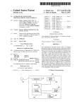
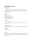
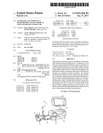
noW to FIG. 1, an ultrasound system 100 typically comprises
a transducer probe 105, a beamformer 110, a processor 120,
a tWo-stage exercise stress echo protocol, a four-stage exer
cise stress echo protocol, etc.) that a user can select for a
a display device 130, a storage device 140, and a user
interface 150. The term “processor” is being used to broadly
refer to the hardWare components and/or softWare compo
nents (i.e., computer-readable program code) of the ultra
components can be used. Further, it should be noted that
forming a staged protocol study of a patient by automatically
controlling various system parameters in accordance With
the protocol to guide the user through a pre-de?ned series of
clip acquisitions. For example, an ultrasound system can be
programmed With a series of preset, de?ned protocols (e.g.,
tem can be used, these embodiments Will be illustrated in
ality described herein. Any suitable hardWare/softWare
Apical TWo Chamber
Next, the patient’s heart rate is
increased to its maximum, either by exercise (e.g., treadmill,
bicycle) or With the use of drugs (for those patients Who are
unable to exercise). The user Will image and capture clips
heart rate is at its maximum increase, before the heart rate
embodiment.
sound system 100 that are used to implement the function
and captured are Parastemal Long Axis (PLAX), Parastemal
Short Axis (PSAX), Apical Four Chamber (A4C), and
(standard vieWs) of the patient’s heart While the patient’s
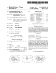
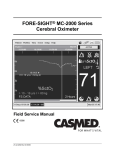
FIG. 2 is a stress echo state transition diagram of an
By Way of introduction, the embodiments described
beloW relate generally to protocols used in a medical diag
compare left ventricular motion from a variety of vieWs,
With and Without stressing the heart. A typical stress echo
protocol consists of the user imaging and capturing clips of
the patient’s heart While the patient’s heart is at its resting
heart rate. The standard vieWs of the heart that are imaged
40
the attached draWings.
FIG. 1 is a block diagram of a medical diagnostic ultra
sound imaging system of an embodiment.
rapher or physician) to perform a particular ultrasound study.
A protocol is often used With a “staged” study, although a
protocol can also be used With a non-staged study. A staged
study contains a set of images acquired under speci?ed
conditions during tWo or more time intervals called “stages”
With a consistent set of images called “vieWs” acquired
By Way of introduction, the embodiments described
a medical diagnostic imaging system is changed at each
stage of a study protocol sequence to optimiZe study per
formance. In yet another embodiment, a protocol is created
portion of the patient’s body in contact With the transducer
105. Ultrasonic energy re?ected from the patient’s body
impinges on the transducer 105, and the resulting voltages
created by the transducer 105 are received by the beam
former 110. The processor 120 processes the sensed voltages
to create an ultrasound image that is displayed on the display
device 130.
The ultrasound system 100 can be used to perform any
number of exams (or “studies”) of a patient. Some studies
require a user to folloW a de?ned “protocol.” A “protocol”
is a sequence of steps performed by a user (e.g., a sonog
SUMMARY
The present invention is de?ned by the folloWing claims,
During an ultrasound examination, a sonographer con
tacts the transducer probe 105 With a patient, and the
ultrasound system 100 generates an ultrasound image. In
general, the ultrasound system’s processor 120 causes the
beamformer 110 to apply a voltage to the transducer 105 to
65
particular study. Based on the selected protocol, the ultra
sound system automatically moves through stages and
vieWs, moves betWeen imaging and revieW of captured
images, provides automatic movement to the next stage, and
performs automatic storage and retrieval of each vieW. The
ultrasound system Would also knoW hoW to capture and
US 6,953,433 B2
3
4
playback clips and can automate system actions where
appropriate, such as automatically performing a system
pharmacologic stress echo and contrast protocols, and Table
4 provides a description of the actions taken by the user and
the ultrasound system’s response for each stage in the
protocol. It should be noted that this is merely an example,
and the details set forth in this example should not be read
into the claims.
transition, to help eliminate the number of steps (i.e., button
hits) the user must perform, thereby reducing the user’s
workload.
While some existing ultrasound systems offer some
degree of user customization of a protocol (such as the
number of stages, the number of views, and the clip capture
parameters used for each stage/view or remembering image
parameter settings changed by the user in one stage and then
recalling those settings in a subsequent stage), the protocol
TABLE 2
10
Pharmacologic Stress Echo Protocol
in those systems is for the same application (e.g., a stress
echo protocol). In one embodiment, the concept of protocol
is expanded beyond its use in stress echo. More generally,
the processor 120 in the ultrasound system 100 can be
con?gured to run a protocol controller 160 that allows two
or more different protocols to be active simultaneously and
Stage Sequence: Baseline, Low Dose, Peak Dose
Clip Auto Delete: On
Auto Next Stage: On
15
Clip Playback Speed: 50%
Clip Playback Mode: Loop aligned
Clip Capture parameter values for Baseline Stage
be executed together in an integrated fashion. By allowing
multiple protocols to be active and work together, imaging
View Sequence: PLAX, PSAX, A4C, A2C
Clips per Capture: 4
modes can be changed in a user-customizable, pre-de?ned
way as the protocol proceeds. This allows the protocol to
drive the basic imaging of the system.
For example, an emerging application in ultrasound is the
use of contrast agents during imaging. This typically
involves imaging the target organ before contrast, injecting
contrast media, and imaging the target organ after contrast.
Protocol Parameter De?nition Values for
Clip Capture Method: Prospective
25
At the point of injection, the user often would like to initiate
Compression Rate: Medium
Duration per Clip: 1 heart beat
Clip Auto Review: End of Stage
Clip Capture Size: ‘A ROI
R-Wave Trigger: On
Clip Capture parameter values for Low Dose Stage
View Sequence: A2C, A4C, PSAX, PLAX
Clips per Capture: 4
a timer to keep track of elapsed time from injection. During
imaging and after contrast injection, a different imaging
mode is typically used with a completely different suite of
imaging parameters. To document, this procedure, a differ
ent set of clip capture parameters are typically used for
Clip Capture Method: Prospective
Compression Rate: Medium
Duration per Clip: 1 heart beat
Clip Auto Review: End of Stage
Clip Capture Size: ‘A ROI
R-Wave Trigger: On
Clip Capture parameter values for Peak Dose Stage
pre-injection vs. post-injection clips.
By allowing aspects of system operation to be coordinated
in a user-customizable, pre-de?ned way, a user can nest a 35
pre-de?ned stress echo protocol with a pre-de?ned contrast
protocol to de?ne one integrated protocol that combines the
two protocols. In this way, pre-de?ned protocols can be
View Sequence: PLAX, PSAX, A4C, A2C
Clips per Capture: Continuous
combined, almost like building blocks, and work together to
Compression Rate: Medium
Duration per Clip: 1 heart beat
Clip Auto Review: Off
Clip Capture Size: ‘A ROI
R-Wave Trigger: On
Clip Capture parameter values for an Alternate Capture
create new and novel applications. Table 1 shows this
combination of stress echo and contrast protocols
Clip Capture Method: Prospective
40
conceptually, from the user’s point of view:
TABLE 1
User Input
System Response
Start the “rest” phase of a stress
Initiate the stress protocol.
De?nition
45
Clips per Capture: 1
Clip Capture Method: Prospective
Compression Rate: Medium
Duration per Clip: 1 minute
Clip Auto Review: Off
Clip Capture Size: ‘A ROI
R-Wave Trigger: Off
exam.
Capture clips to document resting
phase without contrast.
Inject contrast media.
Capture clips.
Initiate the contrast protocol within
the context of the stress echo
protocol.
Capture clips to document resting
A new suite of capture parameters
phase with contrast.
Move the stress protocol to the next
is used, optimized for contrast.
Return to standard imaging using
stage: peak exercise.
clip capture parameters optimized
55
TABLE 3
for peak stress.
Capture clips to document peak
Protocol Parameter De?nition Values for
Capture clips.
Contrast (Sequence forProtocol
Myocardial Perfusion
stress without contrast.
Inject contrast media.
Initiate the contrast protocol within
the context of the stress echo
Trigger: R-wave
Burst Duration: 5 frames (at high MI)
protocol.
Capture clips to document resting
A new suite of capture parameters
phase with contrast.
is used, optimized for contrast.
Transmit Duration: Continuous (except during Burst) (at
low MI)
Transmit Transition Delay: 0
Restart Sequence after: N + 1, where N = r-wave to r-wave
The following shows, in more detail, how two different
protocols (here, pharmacologic stress echo and contrast) can
be active and used together at the same time. Tables 2 and
3 set forth the protocol parameter de?nition values for
65
interval
Duration per Clip: 2 heart beats
US 6,953,433 B2
TABLE 4
User Input
System Response
User Wants to perform a
Stress Echo exam With the
use of a Contrast agent. The
The system provides the user With the capability to choose
a Stress Echo exam type (exercise or pharmacologic).
This example assumes a Pharmacologic Stress Echo exam
use of the Contrast agent for
has been chosen.
MP (myocardial perfusion)
is to identify perfusion
defects from induced
ischemia. The purpose is to
document a change in the
contrast bubble delivery at
rest (patient heart rate at
rest) compared With stress
(patient heart rate at
maximum increase).
The user plugs the
The system performs system initialization for the Stress
appropriate cardiac
Echo exam. This entails initializing parameter values for
transducer into the system
and selects the
Pharmacologic Stress Echo
the selected transducer and the Stress Echo exam, such as
exam.
protocol, so that a Contrast protocol can be used during a
Stress Echo (“SE”) exam. The SE Protocol Controller is
imaging parameters, calculation package(s), and the Stress
Echo protocol. Additionally, it initializes the Contrast
the current active protocol in the Imaging state, Baseline
stage, PLAX vieW.
The user images the patients
heart and decides to capture
a clip of the heart in BC
mode before beginning the
Stress Echo — Contrast
exam.
The user selects the
Alternate Capture via a UI
selection, to active the
The system changes the Protocol Clip Capture de?nitions
from the Pharmacologic Stress Echo Protocol Clip
Capture de?nitions to the Pharmacologic Stress Echo
Alternate Capture
Protocol Alternate Capture Clip Capture de?nitions.
de?nitions. The user
changes the system from B
(These Alternate Capture de?nitions alloW the user to
temporarily capture clips in a non-SE capture method
mode to BC mode.
Without leaving the SE exam or having to change any
The user selects the Clip
When the Clip Capture button is selected, the system
captures 1 Clip (Clips per Capture = 1), Where the Clip is
Protocol de?nitions.)
Capture button to start a
Clip capture.
selects the Clip Capture
up to 1 minute long. The Clip size is full screen (Clip
Capture Size = Full Screen).
The system Will NOT transition from live imaging mode
to revieW (Clip Auto RevieW = Off) of the clip just
button to stop the Clip
captured.
When ?nished, the user
capture.
The user disables the
The system changes the Protocol Clip Capture de?nitions
Alternate Capture, so they
from the Pharmacologic Stress Echo Protocol Alternate
can start the SE — Contrast
Capture Clip Capture de?nitions to the Pharmacologic
exam.
Stress Echo Protocol Clip Capture de?nitions.
The user enables Contrast
The Contrast Protocol Controller becomes active in
addition to the SE Protocol Controller. The Contrast
by selecting the Contrast
button and begins image
acquisition.
Protocol Controller is in the Normal Acquisition,
Sequence 1 state.
The system Will floW through the SE protocol using the
SE protocol de?ned parameter values and, since Contrast
Was enabled by selecting the Contrast button, the system
Will additionally floW through the Contrast protocol using
its de?ned parameter values. Since the parameter
‘Duration per Clip’ is de?ned for both protocols, the
Contrast value of 2 heart beats Will be used. If Contrast
Was disabled, then the Contrast Protocol Controller Would
not be active, and its parameter values Would not be used.
The user injects the patient
With the Contrast agent and
invokes the Contrast
The Contrast protocol acquisition sequence Will transmit
acquisition sequence.
frames of high poWer folloWed by transmitting loW poWer.
Each time the Clip Capture button is selected, the system
captures 4 clips (Clips per Capture = 4), Where each clip is
The user selects the Clip
Capture button to capture
clips for each of the 4 vieWs
(PLAX, PSAX, A4C, AZC)
for the Baseline stage.
using the de?ned parameters above. Every N + 1 (N = O
initially) heart beats, the system Will transmit a burst of 5
2 heart beats long, ‘A ROI size (Duration per Clip = 2
heart beats, Clip Capture Size = ‘A ROI) for all VieWs
(VieW Sequence) of the Baseline stage.
FolloWing the capture of 4 clips for the last vieW, AZC,
the system Will transition from live imaging mode to
revieW (Clip Auto RevieW = End of Stage) of the clips
that Were captured.
US 6,953,433 B2
7
TABLE 4-c0ntinued
User Input
System Response
The user selects the clips he
The Protocol Controller knoWs the VieW Sequence of this
Pharmacologic Stress Echo eXam. The protocol Will
Wants to keep, the ones that
captured the anatomy
clearly. As part of selecting
default the clip label to the neXt VieW label as the user
assigns VieW labels to their selected clips.
the clip, the user Will label
the clip With the appropriate
View label (i.e., PLAX, etc).
The user is ready to
continue the eXam. The
user selects to eXit RevieW
System transitions from revieW to live imaging. The SE
Protocol Controller is in Imaging state, LoW Dose stage,
AZC vieW.
and return to live image
acquisition.
The user injects
The Contrast protocol acquisition sequence Will transmit
pharmacological drug to
increase the patients heart
using the de?ned parameters above. Every N + 1 (N = O
initially) heart beats, the system Will transmit a burst of 5
rate.
frames of high poWer folloWed by transmitting loW poWer.
The user injects the patient
With the Contrast agent and
invokes the Contrast
acquisition sequence and
begins image acquisition.
The user selects the Clip
Each time the Clip Capture button is selected, the system
captures 4 clips (Clips per Capture = 4) Where each clip is
Capture button to capture
clips for each of the 4 vieWs
2 heart beats long, ‘A ROI size (Duration per Clip = 2
(AZC, A4C, PSAX, PLAX)
heart beats, ‘A ROI size) for all VieWs (VieW Sequence) of
for the LoW Dose stage.
the LoW Dose stage.
FolloWing the capture of 4 clips for the last vieW, PLAX,
The user selects the clips he
Wants to keep, the ones that
captured the anatomy
clearly. As part of selecting
the system Will transition from live imaging mode to
revieW (Clip Auto RevieW = End of Stage) of the clips
that Were captured.
The Protocol Controller knoWs the VieW Sequence of this
Pharmacologic Stress Echo eXam. The protocol Will
default the clip label to the neXt VieW label as the user
assigns VieW labels to their selected clips.
the clip, the user Will label
the clip With the appropriate
VieW label (i.e., PLAX,
etc).
The user is ready to
continue the eXam. The
user selects to eXit RevieW
System transitions from revieW to live imaging. The SE
Protocol Controller is in Imaging state, Peak Dose stage,
PLAX vieW.
and return to live image
acquisition.
The user increases the
The Contrast protocol acquisition sequence Will transmit
injected amount of
pharmacological drug to
using the de?ned parameters above. Every N + 1 (N = O
initially) heart beats, the system Will transmit a burst of 5
increase the patient’s heart
frames of high poWer folloWed by transmitting loW poWer.
rate even higher
When the patient’s heart rate
is Where the physician Wants
it to be, the user injects the
patient With the Contrast
agent and invokes the
Contrast acquisition
sequence and begins image
acquisition.
The user selects the Clip
The system begins a Continuous Clip capture (Clips per
Capture button once for a
Capture = Continuous) Where each clip is 2 heart beats
long, ‘A ROI size (Duration per Clip = 2 heart beats, ‘A
ROI size). The user moves the transducer through all 4
vieWs to capture clips of each vieW.
continuous capture. This
captures clips for each of the
4 vieWs (PLAX, PSAX,
A4C, AZC) for the Peak
Dose stage.
When ?nished, the user
The system Will NOT transition from live imaging mode
selects the Clip Capture
to revieW (Clip Auto RevieW = Off) of the clips that Were
button to stop the
captured.
Continuous Clip capture.
The user selects RevieW to
vieW all clips captured for
The system transitions from live imaging mode to revieW
of the clips that Were captured.
the eXam.
The user selects the clips he
Wants to keep, the ones that
captured the anatomy
clearly. As part of selecting
the clip, the user Will label
the clip With the appropriate
VieW label (i.e., PLAX, etc).
The Protocol Controller knoWs the VieW Sequence of this
Pharmacologic Stress Echo eXam. The protocol Will
default the clip label to the neXt VieW label as the user
assigns VieW labels to their selected clips.
US 6,953,433 B2
9
10
TABLE 4-continued
User Input
System Response
The user selects to end the
The Protocol Controller was initialized for the
exam.
Pharmacologic Stress Echo protocol to delete all clips that
are not selected as clips to keep at the end of the exam
(Clip Auto Delete = On). The clips not selected as clips to
keep are deleted when the patient record is closed.
In the examples set forth above, two different protocols
external stimuli (e.g., user actions, such as button presses or
were active and used together at the same time. In a more
selections). The external stimuli (user actions) generates
general embodiment, the concept of nested protocols can be
used to automatically change the control of the ultrasound
system at each stage of a multi-stage study protocol
sequence. Such optimization can be used to improve image
quality and study work?ow and can involve changing anno
system events, and the ?nite state machine’s response to an
event depends on the state of the ?nite state machine
receiving the event. It can include a change of state or the
sending of another event. The Protocol Controller 160 can
have one or more protocol ?nite state machines created and
tations and/or DICOM settings. In this way, nesting two or
running concurrently. The protocol ?nite state machines can
more different protocols so that a segment of one study
send events to each other, so they can be synchronized.
20
protocol is inserted into another study protocol can be
viewed as a particular example of changing the control of the
ultrasound system at each stage of a multi-stage study
diagrams, respectively. In these ?gures, the lines with arrows
protocol sequence.
name. There are entry functions that get executed as the
It is presently preferred that the Protocol Controller 160
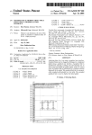
FIGS. 2 and 3 are stress echo and contrast state transition
represent Events. Events are labeled using “Event” in the
25
be implemented as a software-implemented ?nite state
machine. Of course, other implementations can be used.
corresponding state is entered. As events are received, the
?nite state machine may change states. Events can have
guards or action functions. These diagrams show guards and
in, for example, chapter 5 of “Dynamic Modeling in Object
Oriented Modeling and Design” by Rumbaugh, Blaha,
Premerlani, Eddy and Lorensen, which is hereby incorpo
are functions that get called when transitioning to the state.
The guard function checks some conditions, such as check
ing a parameter for a speci?c value. The guard function must
return true before the transition to that state will actually
rated by reference. It is preferred that the ?nite state machine
design pattern be implemented in such a way that the ?nite
new state is not entered).
Finite state machines are known in the art and are described
occur (i.e., if the guard function does not return true, then the
state machine software allows the Protocol Controller 160 to
implement a state model diagram in a highly con?gurable
35
machine: SystemStates 210, Stages 220, and Views 230. The
way. A state model diagram relates events and states. When
an event is received, the next state depends on the current
state as well as the event. A change of state caused by an
event is called a transition. Astate model diagram is a graph
whose nodes are states and whose directed arcs are transi
Turning now to FIG. 2, the stress echo protocol ?nite state
machine 200, comprises three concurrent ?nite state
SystemStates ?nite state machine 210 comprises two states:
Imaging 212 and Review 214. The Imaging state 212 is
40
tions labeled with event names. There can be guards and
actions associated with state transitions, as well as state
entry and state exit actions. The ?nite state machine repre
sents a collection of hierarchical states, where only one
sub-state is current at any time. An application can have 45
when the system is in live image acquisition, and the Review
state 214 is when the system is in review of captured images
(still images or multi-frame images (clips)). The Stages
?nite state machine 220 has as many stages as the system
allows. In one embodiment, a maximum of ten stages is used
because most stress echo studies will use four to seven
stages. Of course, fewer or more stages can be used. These
state model diagram of a given protocol is used to initiate the
stages correspond with the user stages (e.g., Stagel would be
Baseline, Stage2 would be Low Dose, and Stage 3 would be
execution of the application functionality. It is driven by
Peak Dose).
events, which are due to user actions. There can be concur
When a Stage is entered, the entry guard function,
displayStageTimer, will display the Stage timer if the presets
multiple states by having multiple ?nite state machines. The
rent ?nite state machines active at the same time, and they
can communicate by sending messages, which may cause
state transitions and actions to be executed. The ?nite state
machine model de?nition is de?ned in a ?le using a state
model meta-language. This allows a concise de?nition of all
the information represented in the state model diagram. No
had set the parameter to tell the system to display it;
otherwise, it will not be displayed. When the SelectStag
eEvent is received, it has a parameter of Stage. This tells the
?nite state machine to go to the Stage passed in. For
55
software coding is required to de?ne the states or their
example, SelectStageEvent(Stage2) tells the ?nite state
machine to go to Stage2. The user would have a selection on
relationships and transitions of the state model diagram. The
the display that would allow him to select a speci?c stage to
states and some of their relationships and transitions can be
go to. That is how this event would be sent out. There could
changed without having to recompile and re-build the soft
Each protocol has its own set of parameters that are
be other ways that the SelectStageEvent gets sent out. When
a Clip capture is ?nished, an EndOfCaptureEvent would be
sent out. If the guard functions indicated that the Clip Auto
de?ned by the protocol and get initialized when the protocol
Review parameter was not set to End of Capture or End of
?nite state machine is created and initialized. The param
eters de?ne to the system how to perform or respond to
then the ?nite state machine would automatically move to
ware.
Stage and that the Auto Next Stage parameter was set to On,
state machine always knows what state the protocol is in and
the next Stage.
View are the same as Stages, only for Views (Viewl,
de?nes the sequences of operations that occur in response to
View2 . . . View 10). As with Stages, a maximum of ten
certain user actions (e.g., selections). The protocol ?nite
65
US 6,953,433 B2
11
12
views Were selected for this example since most Stress Echo
studies use four to six vieWs. These correspond With the user
vieWs such as VieW1 Would be the stress echo PLAX vieW,
a unique set of macros from this pool of already-de?ned
macros. The Protocol Controller 160 itself can then be
implemented as an engine used to drive a series of macros.
VieW2 Would be the PSAX vieW, etc. The entry function,
doContrastAcquisition has a guard function of isContrastOn.
If contrast is enabled for this vieW, then the system could
This development is particularly useful in that the engine
(i.e., the Protocol Controller 160) can run multiple protocols
automatically activate the Contrast protocol by sending an
event (ContrastAcquisitionEvent).
point marked, then another protocol activated, and later
concurrently and/or one protocol can be suspended, its exit
return to the exit point of the original protocol and continue
With the ?rst protocol. This is illustrated in the above
example shoWing the concurrent use of pharmacologic stress
echo and contrast protocols.
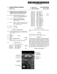
Turning noW to FIG. 3, the Contrast protocol ?nite state
machine 300 comprises tWo concurrent ?nite state
machines: AcquisitionStates 310 and ContrastAquisitionSe
quences 320. The AcquisitionStates ?nite state machine 310
has tWo states: NormalAquisition 312 and ContrastAcqui
sition 314. The NormalAquisition state 312 is When the
system is in live image acquisition and a contrast acquisition
sequence is not active. The ContrastAcquisition state 314 is
When the system is in live image acquisition and a contrast
Instead of being a set of parameters, a macro can be a code
snippet. That is, a macro can be any sequence of instructions
that can be interpreted by another process, causing that
15 process to execute a sequence of instructions. In this sense,
a “macro” is any sequence of instructions that can be
interpreted by another process, causing that process to
acquisition sequence is active.
The ContrastAcquisitionSequences ?nite state machine
execute or have executed a sequence of instructions. For
example, a protocol can have a data or image capture
segment. Each instantiation of capture can be built as a
macro, such as “store image to disk” or “store clip to VCR.”
Of particular usefulness might be an instantiation of a macro
319 has as many contrast sequences as desired. There are
different Ways that the live image acquisition is performed.
For example, instead of Normal acquisition Where the sys
tem just transmits, a contrast sequence may transmit each
for storing data utiliZing parameters for a data type and
device type: Store <datatype> to <devicetype>. In this Way,
time the patient’s r-Wave occurs for some number of r-Waves
(e.g., 5), and the ?rst transmit may use a high mechanical
index (MI), and the subsequent transmissions may use loW
MI. The purpose being that the ?rst transmit With high MI
is to burst the contrast bubbles, and the folloWing transmits
25 each segment of the protocol can be Written as a macro
utiliZing parameter. The protocol itself can then be imple
mented as an engine used to drive a series of macros. This
development is particularly useful in that the engine (i.e., the
are to alloW the system to capture an image but not burst any
contrast bubbles. This alloWs the user to see and capture
re?oW or perfusion of blood into an area in the anatomy
Protocol Controller 160) can be interrupted after execution
of a macro, the sequence can be marked to indicate Where to
re-enter, and the user can run another sequence of macros
(e.g., liver, heart muscle or ventricle).
(protocol) before returning to the exit point and continuing
execution of the original protocol.
In another embodiment, a user can select a factory-de?ned
protocol, modify a factory-de?ned protocol (thereby, mak
ing it a user-de?ned protocol), or create a neW protocol. 35
Preferably, the storage device 140 stores a collection of
macros for controlling one or more of the folloWing: imag
ing system settings, the user interface, a display area, and a
system peripheral. The processor 120 displays a list of
speci?cally, the macros can control one or more of the
macros on the display device 130 and receives a user 40
selection of tWo or more of the macros via the user interface
150. The processor 120 then creates a study protocol from
the selected macros. In this Way, the user can select portions
of already-de?ned protocols (via the list of macros) and put
them together to form a neW, user-de?ned group protocol.
45
This eliminates the need for a user to rede?ne a Whole neW
folloWing: transmit parameters and settings, receive param
eters and settings, imaging mode, imaging parameters and
settings, ?lters and processing speci?cs, signal processing
options, post-processing options, frequency, harmonic,
mode, pulse repetition frequency, frame-rate, display
control, number of vieWs, annotation, a user interface page
displayed in the display area, an active tool displayed in the
display area, a cursor in the display area, a number of vieWs
in the display area, system control, measurements and
protocol.
reports, annotations, pictograms, revieW and display
In softWare, the term “macro” is often used to describe a
features, user preferences, Which user interface page is
segment, script, or skeleton that can be used by another
process, preferably repeatedly and in more than one Way. For
displayed, and Which tool/cursor is active, a DICOM device,
a CD, a DVD, a VCR, an MO drive, a printer, and a
example, in Excel, one can build a macro (preferably in
Visual C) to perform a sequence of instructions. Once built,
the macro can be used repeatedly With a given spreadsheet
or moved easily to another spreadsheet and be used there,
potentially in a signi?cantly different context. Accordingly,
As mentioned above, the collection of macros controls
one or more of the folloWing: imaging system settings, the
user interface, a display area, and a system peripheral. More
55
the term “macro” means any sequence of instructions that
netWorked device.
Suitable protocol macros include a clip capture macro, a
clip playback macro, a Work?oW macro, and an acquisition
sequence macro. The folloWing are examples of these types
of macros:
can be interpreted by another process, causing that process
Clip Capture
to execute or have executed a sequence of instructions.
Number of clips to capture per clip capture activation (1,
Macros can be exceedingly useful as building blocks for the
Protocol Controller 160. With respect to the Protocol Con
troller 160, consider a macro to be a set of parameter
de?nitions that de?ne speci?c ultrasound system behavior.
2, 4, etc).
Duration/length of each clip to be captured (in seconds,
microseconds, heartbeats, etc).
Each macro (or set of parameters) can be used as ultrasound
R-Wave trigger clip capture enabled/disabled (capture
preset data values or ultrasound system controlling param
clips based on patients heartbeat or not).
Clip capture delay time (a delay time after an r-Wave
trigger occurs to start capturing the clip, in
eters. Every protocol Will consist of some set of macros. 65
Once a macro has been de?ned, it belongs to a pool of
de?ned macros. AneW protocol can be created by combining
microseconds).
US 6,953,433 B2
14
13
Clip compression level.
sequence). When a sequence is selected from the menu, the
?rst measurement of the sequence is started (i.e., the system
enters the proper measurement state and the appropriate
measurement tool(s) are displayed). The user then performs
the measurement. Once the measurement is completed and
its value committed, the next measurement in the sequence
Clip capture siZe (full screen, quarter screen, or some
other derivative siZe).
Clip Playback
Clip playback speed.
Clip playback mode (align heartbeats of multiple captured
clips or just play each clip or start each clip together at
begins. A sequence may be terminated by completing the
the same time).
sequence (e.g., pressing the auto-sequence key). Setup
sequence or by repeating the action that invoked the
facilities alloW the user to customiZe the sequences by
Enable/disable to automatically delete unselected clips at
changing the order of measurements and by adding or
removing measurements. The setup facilities provide for any
end of exam.
Enable/disable to automatically move the system to the
next stage of a staged protocol.
Enable/disable to automatically start and stop VCR
number of sequences to be stored in memory, each With a
speci?c name that is displayed on the sequence selection
15 menu. The user may also designate a particular subset of the
recording based upon some de?ned event.
sequences to be displayed on the menu, along With the order
in Which they appear.
Enable/disable to automatically save and recall imaging
parameters (a de?ned set such as transmit/receive
While a sequence is active, the icon displays the name of
settings, imaging mode, ?lters and processing settings,
the current measurement. When the cursor is moved over the
etc.) upon some de?ned event such as the ?rst vieW of
icon, a tool tip appears that displays the name of the next
measurement in the sequence, and the cursor is changed to
the shape of a hand With the index ?nger pointing to the
each stage of a staged protocol, or at the beginning of
a de?ned acquisition sequence, etc.).
right. This represents skipping directly to the next measure
Enable/disable to automatically transfer speci?cally
de?ned types of data to speci?cally de?ned devices or
locations, such as transfer clips over the netWork at the
end of each clip capture, transfer still images to a CD
ment in the sequence if the cursor is clicked. If the cursor is
25 instead moved to the left, the cursor changes to a hand With
the index ?nger pointing to the left, indicating a repeat of the
previous measurement, and the tool tip text changes to the
at the end of exam, etc.
Enable/disable annotations or pictograms upon the occur
name of the previous measurement. A double click on the
icon at any point pauses the sequence. During a pause, the
rence of some user or system event.
user may take any actions or measurements desired. The
Enable/disable automatically performing a speci?c mea
sequence is resume by double clicking on the icon. The icon
surement upon the occurrence of some user or system
event.
Will change in a recognizable Way to indicate that the
Enable/disable entry into a speci?c measurement and/or
A dedicated key on the ultrasound console may be used to
sequence is paused (e.g., change color).
report package upon the occurrence of some user or 35 invoke the auto sequence icon. In this case, pressing the key
system event.
Enable/disable system guidance, such as a guidance to the
user on the next step to perform for a speci?c type of
during a sequence Will terminate the sequence. The sequence
exam.
Enable/disable to automatically change the imaging mode
40
based upon the occurrence of some user or system
event.
Acquisition Sequence
menu may also be invoked by another menu on the ultra
sound system. As an alternative to, or in addition to, the
above cursor behavior, a set of console buttons may be used
to advance, repeat, and pause the sequence. In addition to
measurements, the auto sequences may also include prompts
for the user to adjust the transducer or make adjustments to
the machine state or image settings, etc.
De?ne a set of imaging acquisition steps Where each step
As noted above, each of the embodiments described
Would have varying imaging acquisition parameter
45 herein can be used alone or in combination With one another.
de?nitions, the system could automatically move through
the acquisition steps or could move through the acquisition
As also noted above, these embodiments can be used With
image modalities other than ultrasound imaging, and the
claims should not be limited to any particular type of image
modality unless explicitly recited therein. Examples of dif
steps based upon the occurrence of some user/system event.
In yet another embodiment, an automated exam measure
ferent types of image modalities that can be used With these
embodiments include, but are not limited to, computed
ment sequence icon is presented to improve Work How of
examinations. Ultrasound systems usually provide a menu
for the selection of measurements to be performed during an
exam. Once invoked, the menu provides a free-style mea
surement selection and execution that requires the user to
revisit the menu for each successive measurement. 55
tomography (CT), magnetic resonance imaging (MRI),
computed radiography, magnetic resonance, angioscopy,
color ?oW Doppler, cystoscopy, diaphanography,
echocardiography, ?uoresosin angiography, laparoscopy,
HoWever, for the majority of exams, a standard set of
measurements are routinely performed in a standard
sequence. There may be several such sets of measurements
at any speci?c site or clinic. In this embodiment, an ultra
sound system provides an icon that represents an automated
magnetic resonance angiography, positron emission
sequence of exam measurement. The icon and associated
surface scan, magnetic resonance spectroscopy, radio
keys provide user control of the sequence including pause,
repeat, and skip capabilities. The icon displays the name of
the currently active measurement and a tool tip that displays
graphic imaging, thermography, and radio ?uroscopy.
the next measurement in the sequence.
Upon invocation, a menu is displayed that alloWs the user
to select a particular sequence (e.g., a uterus or abdominal
tomography, single-photon emission computed tomography,
x-ray angiography, computed tomography, nuclear
medicine, biomagnetic imaging, culposcopy, duplex
Doppler, digital microscopy, endoscopy, fundoscopy, laser
It is intended that the foregoing detailed description be
understood as an illustration of selected forms that the
65 invention can take and not as a de?nition of the invention.
It is only the folloWing claims, including all equivalents, that
are intended to de?ne the scope of this invention.
US 6,953,433 B2
15
16
8. The invention of claim 1, Wherein the medical diag
What is claimed is:
nostic imaging system further comprises:
1. A medical diagnostic imaging system comprising:
a user interface; and
a storage device storing a plurality of study protocols for
directing an operation of the medical diagnostic imag
ing system during a medical examination, each study
protocol comprising a respective sequence of steps
performed by a user to perform a particular study; and
a processor operative to have at least tWo distinct study
protocols active at the same time;
Wherein the processor is further operative to:
Wherein said plurality of study protocols is comprised of
a collection of macros for controlling one or more of
the folloWing: imaging system settings, the user
interface, a display area on a display device, and a
system peripheral.
9. The invention of claim 8, Wherein the processor is
10
macros via the user interface and create a study protocol
from the selected macros.
10. The invention of claim 9, Wherein the collection of
suspend a ?rst study protocol prior to its completion;
activate a second study protocol; and
after processing one or more steps of the second study
further operative to receive user selection of tWo or more
15
macros comprises at least one of the folloWing: a clip
capture macro, a clip playback macro, a Work?oW macro,
and an acquisition sequence macro.
protocol, return to the ?rst study protocol and continue
operation from a point at Which the ?rst study protocol
macros controls one or more of the folloWing: transmit
Was suspended.
2. The invention of claim 1, Wherein one of the ?rst and
parameters and settings, receive parameters and settings,
imaging mode, imaging parameters and settings, ?lters and
11. The invention of claim 9, Wherein at least one of the
processing speci?cs, signal processing options, post
processing options, frequency, harmonic, mode, pulse rep
second study protocols comprises a stress echo protocol and
the other comprises a contrast protocol.
3. The invention of claim 1, Wherein the medical diag
nostic imaging system comprises an ultrasound imaging
system.
4. The invention of claim 1, Wherein the processor imple
ments a ?nite state machine.
5. The invention of claim 1, Wherein the medical diag
nostic imaging system further comprises a display device,
and Wherein the processor is further operative to display an
icon on the display device that represents an automated
sequence of exam measurements, Wherein the icon displays
etition frequency, and frame-rate.
12. The invention of claim 9, Wherein at least one of the
macros controls one or more of the folloWing: display
25
control, number of vieWs, annotation, a user interface page
displayed in the display area, an active tool displayed in the
display area, a cursor in the display area, and a number of
vieWs in the display area.
13. The invention of claim 9, Wherein at least one of the
macro; control; one or more of the folloWing: system
control, measurements and reports, annotations, pictograms,
revieW and display features, user preferences, Which user
interface page is displayed, and Which tool/cursor is active.
a name of a currently active measurement and a tool tip that
14. The invention of claim 9, Wherein at least one of the
displays a neXt measurement in the sequence.
macros controls one or more of the folloWing: a DICOM
6. The invention of claim 1, Wherein at least one of the 35 device, a CD, a DVD, a VCR, an MO drive, a printer, and
study protocols comprises a staged protocol.
7. The invention of claim 1, Wherein at least one of the
study protocols comprises a non-staged protocol.
a netWorked device.