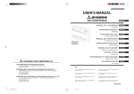
1
Operation Instruction Fire Alarm Control Panel IQ8Control C/M 798950.10.GB0 G 299044 08.2009 G 205129 GB Technical changes reserved! © 2009 Honeywell International Inc. Fire Alarm Control Panel IQ8Control C/M Intended purpose This product must only be used for the applications outlined in the catalogue and the technical description and in combination with external components and systems, which have been approved or recommended by Esser by Honeywell. Warning In order to ensure correct and safe operation of the product, all guidelines concerning its transport, storage, installation, and mounting must be observed. This includes the necessary care in operating the product. Safety-relevant user information This manual includes all information required for the proper use of the products described. The term 'qualified personnel' in the context of the safety information included in this manual or on the product itself designates: • project engineers who are familiar with the safety guidelines concerning fire alarm and extinguishing systems. • trained service engineers who are familiar with the components of fire alarm and extinguishing systems and the information on their operation as included in this manual. • trained installation or service personnel with the necessary qualification for carrying out repairs on fire alarm and extinguishing systems or who are authorised to operate, ground and label electrical circuits and/or safety equipment/systems. Safety warnings The following information is given in the interest of your personal safety and to prevent damage to the product described in this manual and all equipment connected to it. Safety information and warnings for the prevention of dangers putting at risk the life and health of user and maintenance personnel as well as causing damage to the equipment itself are marked by the following pictograms. Within the context of this manual, these pictograms have the following meanings: Warning sign Designates risks for man and/or machine. Non-compliance will create risks to man and/or machine. The level of risk is indicated by the word of warning: Important information on a topic or a procedure and other important information! § Observe configuration and commissioning information in accordance to the national and local requirements. Dismantling In accordance with Directive 2002/96/EG (WEEE), after being dismantled, electrical and electronic equipment is taken back by the manufacturer for proper disposal. 2 FB 798950.10.GB0 / 08.09 Fire Alarm Control Panel IQ8Control C/M 1 General ....................................................................................................................................................................... 4 2 General View – Operating panel front (from 08 / 2009) .......................................................................................... 5 2.1 2.2 Key switch / enabling operation .......................................................................................................................... 7 Function of the display and operating elements................................................................................................ 8 2.3 Operating panel with FBA CH (Part No. 786207) ......................................................................................... 17 3 Operating status of the fire alarm control panel ..................................................................................................... 19 3.1 3.2 3.3 3.4 3.5 3.6 4 Normal condition................................................................................................................................................ 19 Fire ...................................................................................................................................................................... 19 Trouble................................................................................................................................................................ 20 CPU failure ......................................................................................................................................................... 20 Disconnection..................................................................................................................................................... 21 Testmode ........................................................................................................................................................... 21 Operation .................................................................................................................................................................. 22 4.1 Function keys / selection menu ........................................................................................................................ 22 4.1.1 Display / display control ............................................................................................................... 24 4.1.2 Display priority of the messages in the display............................................................................ 26 4.1.3 Info text / additional text and parameter display .......................................................................... 27 4.2 Entering time/date.............................................................................................................................................. 28 4.3 Zones.................................................................................................................................................................. 29 4.3.1 Switching on / resetting a zone.................................................................................................... 29 4.3.2 Disconnect a zone ....................................................................................................................... 30 4.3.3 Status of a zone........................................................................................................................... 31 4.4 Detectors ............................................................................................................................................................ 32 4.4.1 Switching on / resetting a detector .............................................................................................. 32 4.4.2 Disconnect a detector .................................................................................................................. 33 4.4.3 Status of a detector...................................................................................................................... 34 4.5 Controls .............................................................................................................................................................. 35 4.5.1 Switching on a control.................................................................................................................. 35 4.5.2 Disconnect a control .................................................................................................................... 36 4.5.3 Status of a control........................................................................................................................ 37 4.6 Common display of the status messages........................................................................................................ 38 4.7 Delay and Verify................................................................................................................................................. 39 4.7.1 Delay............................................................................................................................................ 40 4.7.2 Verify............................................................................................................................................ 40 4.8 Alarm counter..................................................................................................................................................... 40 4.9 Lamp test............................................................................................................................................................ 41 5 Service Level ............................................................................................................................................................ 42 5.1 5.2 5.3 Sensor functions (loop)...................................................................................................................................... 43 Sensor functions (zone/detector)...................................................................................................................... 45 Primary loop functions (Access levels 3 and 4)............................................................................................... 46 FB 798950.10.GB0 / 08.09 3 Fire Alarm Control Panel IQ8Control C/M 1 General Thank you for buying a product from Esser by Honeywell. The quality and reliability of Esser products are well known and ensure the highest level of safety at their installation location for many, many years. This user manual in combination with the instructions provided by your installer will quickly provide you with extensive information about the operation of the IQ8Control C/M fire alarm control panel. We recommend that you read this user manual thoroughly and keep it together with the technical documentation of the fire alarm control panel. If you have any questions, please contact your installer. To equip buildings, facilities, commonly frequented areas and working spaces with a fire warning system can only be carried out economically and with reasonable propriety when correspondingly well-founded safety concepts are developed and accordingly applied. Wherever the highest requirements are made on a fire warning system, whether in small commercial facilities or in industrial plants, the Fire Alarm Control Panel IQ8Control transforms safety techniques and economy into practical reality. The modular design with different micro modules and individual extension concepts allow the FACP IQ8Control to be easily adapted to special requirements. The FACP IQ8Control represents the most modern standard of fire warning technology. A reliable fire warning facility is guaranteed by the application of "intelligent" fire detectors connected in an analog loop, which is tolerant to short and open circuits. ® ® In this analog loop - the esserbus / esserbus PLus - up to 127 loop devices each capable of being configured into 127 individual zones can be connected with an overall cable length of up to 3,5 kilometres. The esserbus® is a two-wire line supplied and monitored at both ends in ring topology. The Fire Alarm Control Panel IQ8Control automatically registers the wiring of the analog loop and determines the logical addresses of the individual loop devices. A separate adjustment of the addresses of the individual loop devices is unnecessary. Fire alarm panels with esserbus® PLus analog loop provide the direct connection of addressable notification appliances, e.g. sounder to the loop. There is no need of an auxiliary power for these loop devices. Subscribers in the esserbus® are automatic intelligent fire detectors, manual call points and technical alarm modules (TAL) and the specially developed esserbus® transponder input/output devices. These esserbus® transponders are loop devices with freely programmable inputs and outputs, for example for the activation and monitoring of external devices such as display panels, alarm devices, door closers and other connected equipment. Using the essernet® safety network, 31 Fire Alarm Control Panel IQ8Control or other network subscribers such as display and operating panels or alarm devices can be connected in a homogenous network. Operation of the fire warning system, e.g. switching off a zone, is possible from any fire alarm control panel or operating panel in the essernet®. Signals such as alarm, trouble, disconnection or other events are transferred to all subscribers in the essernet® and can be accessed from any desired position. Data exchange can, according to the transfer rate, be carried out either with a twisted pair or a LAN cable. The essernet® communications protocol guarantees reliable data exchange even if a short or open circuit occurs in the network. Additional and updated Informations The described features, specifications and product related informations in this manual correspond to the date of issue (refer to date on the front page) and may differ due to modifications and/or amended Standards and Regulations of the System design, Installation and Commissioning. Updated informations and declaration of conformity are available for comparison on the www.esser-systems.de homepage. esserbus® and essernet® are registered trademarks in Germany. 4 FB 798950.10.GB0 / 08.09 Fire Alarm Control Panel IQ8Control C/M 2 General View – Operating panel front (from 08 / 2009) 2 1 3 4 5 6 7 8 9 10 11 15 14 13 12 Fig. 1: General view of the display and operating elements 1 Single zone indicator unit (GEA) option 2 Common display FIRE 3 Common display PRE-ALARM 4 LED with label field 5 Common display TROUBLE 6 Common display DISCONNECTION 7 Alphanumeric display 8 Function keys – display 9 Key switch 10 Cursor keys – additional messages / information 11 Function keys – general 12 Function keys – commands 2 13 Keyboard 0 – 9 14 Opening for Programming via Serice PC Connector must locked with dummy plug for ESD protection 15 Function keys – commands 1 FB 798950.10.GB0 / 08.09 5 Fire Alarm Control Panel IQ8Control C/M Access levels When enabling the operating panel for operation using the key switch and the access code for the relevant access authorisation, it can be operated at four different access levels. Access level 1 Housing door closed and key switch locked • Only the buttons >Buzzer off<, >Function key F1< and the Cursor keys for displaying the messages in the display can be used. Access level 2 Housing door closed and key switch released. (Operator) • In this access level, authorised and trained persons can perform operations and query messages. Access level 3 Housing door open, key switch released and access code. (Installer) • This access level allows operation, detailed status display and configuration of the fire alarm control panel by trained and authorised specialists. Access level 4 Housing door open, key switch released and service PC connected. (System configuration) • For programming of the FACP by service technicians and authorised specialists. § 6 Turning off individual alarm units According to EN 54-2, it is prohibited to individually deactivate acoustic alarms. The control panel's standard configuration therefore does not permit such operations or deactivation of an individual line in case acoustic alarm units may be connected here. This configuration can be changed in the control panel programme. FB 798950.10.GB0 / 08.09 Fire Alarm Control Panel IQ8Control C/M 2.1 Key switch / enabling operation The key switch can be used to lock the operating panel keyboard of the fire alarm control panel IQ8Control to prevent unauthorised operation. In normal operating mode, the keyboard should be locked. Key switch in vertical position locked unlocked Fig. 2: Keyboard blocked • The keyboard is blocked. The key can be removed. • The keys >Buzzer off<, >Function key F1< and the Cursor keys for displaying messages in the display can still be operated when the keyboard is blocked. Key switch in horizontal position locked unlocked Fig. 3: Keyboard unlocked • The keyboard is unlocked for the operation of the single IQ8Control and other processors interconnected through the essernet® or other networks. • The display menu is activated. • The common disconnection display may be lit. Depending on the customer data programming, when the keyboard was unlocked, at least one zone, one output or one component of the fire alarm control panel, such as the master box, was switched off. In case of a fire alarm, FACP will disable the activation of the master box (MB). The fire brigade will not be alarmed, automatically. In case of an event, the red LED >Notify fire department< will be lit. Call the fire department immediately! FB 798950.10.GB0 / 08.09 7 Fire Alarm Control Panel IQ8Control C/M 2.2 Function of the display and operating elements The display and operating panel of the FACP IQ8Control are available with the standard display or the larger ¼ VGA display in both variants. In this documentation, the display is described using the 4-line standard display as an example. Slight differences in how information is displayed are possible with the ¼ VGA display. 1 2 1 2 3 5 4 3 5 4 Fig. 4: Operating elements - keypad - display Operating elements - keypad - 1/4 VGA display c Common displays d Alphanumeric display standard or ¼ VGA display e Menu f Function key – display g Cursor key – other messages / information All received signals such as fire, trouble or switch-off are shown in the alphanumeric display in alphanumeric form (8 lines, 40 characters per line). Keyboard By means of the key switch, the keyboard is unlocked for operation. With these keys, it is possible to control panel functions such as switching zones and detectors on and off. Function keys With the four function keys, the menu options positioned above them in the alphanumeric display are selected. Depending on the current state of the fire alarm control panel or the operation level, differing menu options are shown in the display. 8 FB 798950.10.GB0 / 08.09 Fire Alarm Control Panel IQ8Control C/M Fire Releasing System Master Box (MB) Notify Fire Dept. Fig. 5: Common display fire The common display >Fire< is activated if at least one fire alarm has been detected. The originating detector or zone will be shown on the alphanumeric display. If evacuation plans or guidelines exist for cases of fire alarm, these plans have to be followed and the premises have to be evacuated, if necessary. Make sure to inform yourself well in advance about existing escape routes and required measures in case of a fire. Fire (Common display) ⇒ Fire alarm ! An external alarm is triggered. The fire and rescue services are alarmed via the connected master box. If no master box (MFAB) is connected or if this could not be activated, the LED >Call fire brigade< is also on. ⇒ The fire releasing control equipment has been activated. ⇒ The master box (MB) is activated and the intervention staff (e.g. fire department) has been alarmed. ⇒ The master box (MB) has malfunctioned or is switched off and cannot be activated. Fire Red LED is permanently on Fire Releasing System Red LED is permanently on Master box (MB) Red LED is permanently on Notify fire department Red LED is permanently on FB 798950.10.GB0 / 08.09 Call the fire department immediately! 9 Fire Alarm Control Panel IQ8Control C/M Pre-Alarm Delay Verify 1 Fig. 6:Common display pre-alarm and LED with label field A Pre-alarm is signalled when an intelligent fire detector reaches the pre-alarm level or when in a programmed twin-loop/twin detector connection a loop or a detector have detected a fire alarm. The Pre-alarm is automatically reset if no further signals are transmitted. The common display Pre-alarm is extinguished and any activated alarm devices are switched off. If further alarm signals occur, a fire alarm is automatically initiated and the master box (MB) is activated. In case of a pre-alarm, it is important that the detector location and the cause of the alert are verified. Pre-Alarm (Common display) At least one detector or zone is signalling the pre-alarm condition. Pre-Alarm ⇒ Red LED is permanently on The activated detector or the activated zone is indicated on the alphanumeric display. The internal central buzzer also sounds. Control actions assigned to this event by means of customer data programming, e.g. relay outputs for activating internal signalling devices or evacuation signals will be executed. On pre-alarm, the master box for alarming the emergency services will not be activated. 10 FB 798950.10.GB0 / 08.09 Fire Alarm Control Panel IQ8Control C/M Delay An on/off switching interval has been programmed for the delay function. During this time, the activating of the master box (MB) due to a Yellow LED is permanently on ⇒ fire alarm is automatically delayed by the delay time programmed in the customer database. An alarm signal has been detected during the active delay time. ⇒ Yellow LED blinks The programmed delay time has been initiated. The master box is activated after expiry of this time. Verify The key >Verify< has activated the function Verify. ⇒ Yellow LED is permanently on The programmed Verify time for the Verify of the cause of the alarm is running. The master box is only activated after the expiry of the Verify time. The function >Delay/Verify< is described in chapter 4.7. LED with label field This LED can be assigned a building-specific display function in the customer data programme of the control panel. The label field and/or supplied label stickers can be used to label this customisable display function. ⇒ The assigned function is active. ⇒ The assigned function is active. Yellow LED blinks Alternative programming: Yellow LED is permanently on FB 798950.10.GB0 / 08.09 11 Fire Alarm Control Panel IQ8Control C/M Trouble in Operation CPU Failure Power Supply Fig. 7: Common display TROUBLE The common display Trouble is activated if at least one malfunction has been detected. The reason will be shown on the alphanumeric display. Trouble (Common display) Trouble ⇒ A component of the fire alarm control panel or a monitored relay output such as an external alarm device or a master box has malfunctioned. ⇒ The power supply (battery or mains voltage) is connected. The fire alarm control panel is in an operative condition. Yellow LED is permanently on Operation Green LED is permanently on CPU failure The fire alarm control panel is only partially operative due to a malfunction of the control panel functions. Display or operation of the control panel is no longer possible (Exception: Key Buzzer off). Yellow LED is permanently on ⇒ The activating of the master box (MB) and the LED >Master box< (MB) and >Notify fire department< is still operative in the CPU failure mode of the control panel in the case of a fire alarm. Power supply ⇒ The power supply (battery or mains voltage) is out of order. Yellow LED is permanently on In cases of malfunction or emergency operation, correct functioning of the FACP is no longer ensured. Inform customer/maintenance service! 12 FB 798950.10.GB0 / 08.09 Fire Alarm Control Panel IQ8Control C/M Disconnection Relay Outputs Master Box Testmode Fig. 8: Common display Disconnection The common display >Disconnection< indicates that at least one output, input, or other component of the FACP has been disconnected. The disconnection will also be shown on the alphanumeric display. Disconnection (common display) Disconnection ⇒ At least one input/output e.g. a zone or relay has been switched off. ⇒ At least one relay output such as an internal control panel relay or the control of an esserbus® transponder has been switched off. Yellow LED is permanently on Relay Outputs Yellow LED is permanently on Master box (MB) Access level 3: ⇒ Yellow LED blinks Activation of the master box is automatically prevented by the opened tamper switch (no deactivation!). In case of an event, no automatic activation takes place. This condition is only changed by closing of the tamper switch (no button function)! Access level 2: ⇒ Yellow LED is permanently on The master box (MB) is switched off, e.g. for servicing, by enablement of the keyboard with the key switch. Testmode ⇒ A component of the control panel (e.g. zone) has been set to Testmode for servicing and maintenance work. Yellow LED lights A switched off master box will not transmit an alarm signal in the case of an event! A zone in Testmode will not transmit an alarm in the case of an event. FB 798950.10.GB0 / 08.09 13 Fire Alarm Control Panel IQ8Control C/M Fig. 9: Single zone indicator units (GEA) Optical displays (LED) for a total of 64 zones may be integrated into the control panel of the IQ8Control. Fire is signalled by a red LED. A yellow LED signals malfunctions and disconnections. There is a labelling field for each zone, which can be marked with the name of the zone or of the area monitored by this group of detectors. Fire ⇒ At least one detector and / or one manual call point in the zone is signalling a fire alarm. ⇒ For the zone, which first signalled the fire alarm (initial alarm detection). Red LED is permanently on Red LED blinks Disconnection / Trouble The zone is switched off. ⇒ Switching zones on/off refer to chapter 4.2. Yellow LED is permanently on At least one detector of the zone has malfunctioned. ⇒ Inform customer/maintenance service! Yellow LED blinks Switched off or malfunctioning zones will not transmit an alarm in the case of an event. 14 FB 798950.10.GB0 / 08.09 Fire Alarm Control Panel IQ8Control C/M Panel reset Panel reset All detected fire alarms, zones, displays and technical alarm signals (TAL alarm) are cancelled and returned to normal condition. Access level 2 (keyboard release with key) required. Audible Alarm off / silence Audible Alarm off / silent Access level 2: Activated alarm units can be silenced or enabled again by pressing the button (toggle function). Depending on the programming of the fire alarm control panel, silenced alarm units are automatically activated again upon every new event. The common display >Alarm off< visually indicates if alarms are deactivated. Special function in access level 3: In access level 3, pressing of the button switches the connected alarm units permanently off. They are not reactivated by subsequent events. The common display >Alarm off< also lights up. When exiting access level 3, this function returns to the initial state access level 2 Disconnect Master Box Disconnect M aster Box The activating of the main alarm unit / the master box (MB) is switched on or off (toggle function). Switch-offs are displayed visually in the Common display disconnection field. Switched off alarm devices and master boxes will not transmit an alarm in the case of an event. The fire brigade is not notified automatically. FB 798950.10.GB0 / 08.09 15 Fire Alarm Control Panel IQ8Control C/M Verify Verify If the >Delay function< is activated, pressing this button during an event starts the investigation time for delayed activation of the master box. The first and last messages with the highest priority appear in the display again without the need to press any other buttons. The > Verify < function is described in Chapter 4.7. Additional messages are shown on the display. They can be selected with the Cursor keys. The first and last messages with the highest priority appear in the display again without the need to press any other buttons. Delay Delay When this key is pressed, the delay time is enabled/disabled (toggle function). Refer to chapter 4.7 Delay/Verify. Buzzer off Buzzer off Acknowledgement of the control panel buzzer. This key remains active when the keyboard is locked. The buzzer is reactivated in the case of a further event. 16 FB 798950.10.GB0 / 08.09 Fire Alarm Control Panel IQ8Control C/M 2.3 Operating panel with FBA CH (Part No. 786207) The panel front with integrated Fire department operating and indicating panel (FBA) is an optional device for use of the Fire Alarm Control Panel IQ8Control in Swiss. In accordance to the requirements of the common national Fire assurance companies (VKF-Swiss) each Fire Alarm Control Panel must be installed at an accessible place for the fire department and must be equipped with the standardised Fire department operating and indicating panel (FBA) 1 Fig. 10: panel front with integrated Fire department operating and indicating panel (FBA) c Fire department operating and indicating panel (FBA) Any other operating elements comply with the functionality of the panels standard front in chapter 2.1. For additional versions of the operation panel front with a built-in Fire Department Notifying and Indication unit refer to the Fire systems catalogue. FB 798950.10.GB0 / 08.09 17 Fire Alarm Control Panel IQ8Control C/M Fire alarm Î red LED is permanently on ⇒ This LED is a common fire indication. At least one fire message has been detected. Trouble Î yellow LED is permanently on ⇒ This LED is a common trouble indication. At least one failure message has been detected. Switched off or malfunctioning zones will not transmit an alarm in the case of an event. Fire alarm Î red LED is permanently on ⇒ The remote alarm is activated and e.g. the fire department is notified. The LED lis until this message is manually resetted at the panel. Audible alarm OFF ⇒ Pressing the button quits the started audible alarm of an fire or trouble message. Panel reset ⇒ Press the button to reset the Fire Alarm Control Panel (incl. all zones and alarm devices). Key switch (Lock/unlock keyboard) ⇒ 18 The keys >Audible alarm off< and > Panel reset < can still be operated when the keyboard is locked. FB 798950.10.GB0 / 08.09 Fire Alarm Control Panel IQ8Control C/M 3 Operating status of the fire alarm control panel The current operating status of the IQ8Control is shown on the operating panel. Six different operating conditions are possible. 3.1 Normal condition The normal condition refers to an operative monitoring state of the control panel unchanged by external influences. • The green LED >in Operation< lights. • No further displays or messages. • The key switch locks the operating panel keyboard. 3.2 Fire • The control panel is in alarm mode, i.e. it is signalling a fire alarm. • The common display FIRE (red LED) lights. • The master box (MB) has been activated. • The internal control panel buzzer sounds. • External alarm devices, e.g. acoustic alarm devices or control panel buzzers are activated. • The zone, which has detected the fire, is shown in the display with the programmed additional text. • The red LED of the corresponding zone(s) lights in the single zone indicator units (optional). If several zones signal a fire alarm, the red LED of the zone, which first detected the fire, blinks (initial alarm detection). • The red LED >Master box (MB)< lights when a master box for automatic transmission of the alarm is connected and the fire department has been informed. • Possibly, the red LED >Notify fire department< may light. The fire department has not been informed via the master box. • Call the fire department immediately! FB 798950.10.GB0 / 08.09 19 Fire Alarm Control Panel IQ8Control C/M 3.3 Trouble The common display TROUBLE (yellow LED) lights and the control panel buzzer sounds intermittently. • At least one control panel function has failed! • A message is shown in the display describing the failure/cause. • The yellow LED of the zone in which the malfunction has possibly occurred blinks on the single zone indicator units (optional). Zones/relay loops or inputs/outputs will not signal an alarm in the case of an event. Inform customer/maintenance service! 3.4 CPU failure The fire alarm control panel is only partially operative! • No messages on the alphanumeric display. • No evaluation of information. • No activation of external equipment such as alarm sounders. • The master box and the >Master box (MB)< LED and Notify fire department will be activated even in the control panel CPU failure mode. A comprehensive operation in a CPU-failure mode (emergency operation) or system fault of the fire alarm control panel is no longer provided. Call customer/maintenance service immediately! 20 FB 798950.10.GB0 / 08.09 Fire Alarm Control Panel IQ8Control C/M 3.5 Disconnection The normal condition of the control panel has been changed by an external influence. Displays: • The common display >disconnection< (yellow LED) lights. • Possibly, a further display in the Common display disconnection field may be signalled, showing which components have been switched off, e.g. >Relay or Master box (MB)<. • The disconnection is reported in the display as a plaintext message. • A switched off zone is indicated on the single zone indicator units (optional) by a permanently lighting yellow LED. Switched off zones, detectors and controls (AE) and other parts of the equipment will not signal an alarm in the case of an event! 3.6 Testmode The yellow LED >Testmode< is permanently on. The >Testmode< mode of the control panel has been activated for service and maintenance purposes: • The function of detectors/zones is under inspection. A zone in Testmode will not signal an alarm in the case of an event. FB 798950.10.GB0 / 08.09 21 Fire Alarm Control Panel IQ8Control C/M 4 Operation The following section describes the most important operating actions for a single FACP IQ8Control. If several processors are connected in a network through the essernet®, deviations from this description are possible. In this case, please ask your specialised installer. The operation of an installed and operative fire alarm control panel may only be carried out by authorised and trained personnel under observance of the safety precautions and, if necessary, in co-operation with the relevant emergency services (e.g. fire department). 4.1 Function keys / selection menu Overview F1 Service Time func. F2 F3 Info or param. / add. text F4 Fig. 11: Function keys / selection menu Summary of the various menu options The selection menu allows direct access to logically grouped menu options. When the keyboard is unlocked, up to four menu options are constantly shown in the display, each of which can be selected using the function key located below it. Status ⇒ Status display of current messages in order of significance. Summery ⇒ Group display and number of the various types of message, such as >fire<, >trouble<, >disconnection< etc. Service ⇒ Transfer to the service level to operate the primary loop functions such as switching primary loops, sensors etc. on/off. 22 FB 798950.10.GB0 / 08.09 Fire Alarm Control Panel IQ8Control C/M Installer ⇒ Operating actions for the specialised installer for service and maintenance purposes. (Individual password code required, if a code has been programmed.) Time funct. ⇒ Entry of time/date and the switching times of the Delay/Verify function. Escape ⇒ Termination of the current input prompt without storing or executing the function. Acknowledge ⇒ Acknowledge the selected menu point/operation. Function ⇒ Confirmation of the execution of the previously selected function. Rem.Text ⇒ Query of the additional text display (Remote text) of other fire alarm control panels in the essernet® network. If an event has been detected by a fire alarm control panel in the essernet®, the additional text from the activated fire alarm control panel can be displayed by the remote text function on another fire alarm control panel. Information and additional text Info Param/AT ⇒ Display of any programmed information text relating to the message in the alphanumeric display. If information text exists, i.e. has been programmed for this message, the menu point >Info< is displayed. If info text has not been programmed, the menu point Info is not displayed. ⇒ Display of the additional text programmed for the current message or a parameter. For a parameter, a works-programmed information text for the current message in the alphanumeric display is shown. It is possible to switch from additional text/parameter display using the function key. If additional text has not been programmed, the menu point >Add. text< is not displayed. If information or additional text has been programmed for a message, the additional text (Param/AT) is always displayed first. Pushing the function key during the display of the additional text shows the information text. FB 798950.10.GB0 / 08.09 23 Fire Alarm Control Panel IQ8Control C/M 4.1.1 Display / display control 1 1 1. FIRE Det 3. FIRE Det Overview Zone : 002 Det : 02 Office 1 Room 17 1st floor 2 3 15:10 28:07 4 15:10 Zone : 002 Det : 02 EDP room Room 21 1st floor Service Time func. 28:07 Info 5 Fig. 12: Example display for a fire alarm incl. detector information (example) c In all, three fire signals were detected. The display shows the first (1.) and the last signal (in this case 3.) incl. group and detector information respectively. Pressing the cursor key scrolls the display, and the next signal (2.) is displayed. d Time of this alarm message. e Date of this alarm message. Additional text line f (the additional text programmed for the triggered zone or detector will be displayed). g Additional information text or parameter / additional text (Param/AT). Significance of the display to "1. Fire" : • First fire signal on 28.07 at 15:10 hours. • The detector No. 02 in the zone No. 02 signals Fire. • The additional text programmed for this zone >Office 1 Room 17 1st floor< provides information on the location of the fire. • The display field >Info< shows that an information text has been programmed for this zone, which can be accessed by pressing the corresponding function key. 24 FB 798950.10.GB0 / 08.09 Fire Alarm Control Panel IQ8Control C/M 1) First / last message with the next higher priority 2) A next message with equal priority / additional messages 3) First / last message with the next lower priority 4) Prior message with equal priority Fig. 13: Cursor keys Further Displays / Messages For your information, the following additional messages (if existing) are shown in the alphanumeric display: MB disconnected ⇒ When the activation of at least one master box (MB) for the warning of the fire department has been switched off, e.g. by enablement of the keyboard. MB trouble ⇒ When at least one master box (MB) has malfunctioned. Acoustic trouble ⇒ When at least one acoustic alarm device has malfunctioned. Acoustic disconnected. ⇒ When at least one acoustic alarm device has been disconnected. Revision active ⇒ When the fire alarm control panel has been switched to revision on the fire department operating panel. FB 798950.10.GB0 / 08.09 25 Fire Alarm Control Panel IQ8Control C/M 4.1.2 Display priority of the messages in the display Display priority The first and last messages with the highest current priority are shown in the alphanumeric display of the FACP IQ8Control respectively. If several messages with equal priority are imminent, these can be queried by pressing the Cursor keys. In priority level 1, only groups with a fire message are displayed for increased clarity. The corresponding detectors (FIRE-D) are displayed in priority level 2 messages. Priority stage Condition Display 1 Fire alarm (zone) FIRE 2 Fire (fire detector details) FIRE Det 3 Fire loop FIRE 4 Technical alarm T-ALARM 5 Pre-alarm PRE ALARM 6 Trouble TROUBLE 7 Trouble loop LINE TROUBLE 8 Transfer route switched on (loop) LINE ON 9 System trouble SYS TROUBLE 10 Disconnection DISCONNECTION 11 Disconnection loop LINE OFF 12 Trouble relay output TROUBLE 13 Switch-off relay output O/P OFF 14 Activate ACTIVATE 15 Testmode TEST If the control panel is operated during the display, the corresponding function is carried out. The message with the highest priority reappears in the display automatically without the need to press any additional buttons. 26 FB 798950.10.GB0 / 08.09 Fire Alarm Control Panel IQ8Control C/M 4.1.3 Info text / additional text and parameter display 1. FIRE Det 1 Zone : 002 Det : 02 15:10 Office 1 Room 17 1st floor 28:07 2 Access via stairway right Inform Mr. J. Smith (Tel. 02137 / 99152) Status Param/*T Fig. 14: Info text display (example) c Info Display of any programmed information text relating to the message in the alphanumeric display. If information text exists, i.e. has been programmed for this message, the menu point Info is displayed. If >Info< text has not been programmed, the menu point >Info< is not displayed. d Param/AT Display of the additional text programmed for the current message or a parameter. For a parameter, a works-programmed information text for the current message in the alphanumeric display is shown. It is possible to switch between additional text/parameter display using the function key. If additional text has not been programmed, the menu point >Add. Text< is not displayed. If >information or additional text and a parameter< have been programmed for a message, the information and additional text is always displayed first. Pushing the Param./AT function key during the display of the additional text shows the parameter. Example of an info text display (Fig. 14) Access to programmed information text for this message programmed in the customer data and related to the zones (max. 4 lines / 40 characters per line) can be attained by pressing the function key Info. In this example, the following two-line info text was programmed for zone 02 in a fire condition: Access via stairway right! Inform Mr. J. Smith (Tel. 02137/ 99152) Info text / additional text and parameter display Pressing the Condition function key >returns< the panel to the condition display. The display switches automatically to the preceding menu point without the need to press any additional buttons. FB 798950.10.GB0 / 08.09 27 Fire Alarm Control Panel IQ8Control C/M 4.2 Entering time/date Time fct. Time/Date Time Date Delay on Escape : 10:4 : Tu. 02.06.99 : --:-- off: --:-Function Fig. 15: Entering time/date Entering the time or the date is carried out under the >Time functions< menu point, which is accessed by pressing the corresponding function key. The corresponding input field (hour, minute, day, etc.) is marked using the cursor keys and the desired value is entered on the numeric keypad. When a date is entered >DD.MM.YY<, the day of the week (Mo, Tu, We...) is automatically calculated. Escape ⇒ Exits the menu point without storing the changes/inputs Function ⇒ The numeric values shown in the display are stored Entering times for the function >Delay/Verify<;refer to chapter 4.7! Without the need to press any additional buttons, the display switches back automatically to the last menu point without storing the changes/inputs! 28 FB 798950.10.GB0 / 08.09 Fire Alarm Control Panel IQ8Control C/M 4.3 Zones 4.3.1 Switching on / resetting a zone With switch-on/reset, a zone, which has been switched off -incl. all fire alarms-, is switched into the operative status or an operative zone is reset and any imminent messages such as >Fire or Trouble< are deleted. Zone On 4 Press key Fig. 16: Switching on / resetting a zone 4 (example) Operation Zone: Detector: 4 0 On in progress Fig. 17: Display switching on zone 4 FB 798950.10.GB0 / 08.09 29 Fire Alarm Control Panel IQ8Control C/M 4.3.2 Disconnect a zone With the disconnection, the corresponding zone -incl. all fire alarms- is disconnected. The zone is selected by means of the corresponding zone number. Zone Off 4 Press key Fig. 18: Switching off / resetting a zone 4 (example) Operation Zone: Detector: Off in progress 4 0 Fig. 19: Display switching off zone 4 In addition to the message on the display, the Disconnect is indicated optically by the common display >Disconnect< on the control panel and the corresponding continuous lighting of the yellow LED on the single zone indicator unit (if present). 1. Disconnect Zone: 0004 Det: 15 11:10 22:11 Additional text (client text) Overview Service Time funct. Info Fig. 20: Disconnect to status display A disconnected zone will not signal an alarm in the case of an event! 30 FB 798950.10.GB0 / 08.09 Fire Alarm Control Panel IQ8Control C/M 4.3.3 Status of a zone With this function, the current status, e.g. >Normal<, >Alarm< and >Trouble<, of the corresponding zone can be interrogated directly. Zone Status query 2 Press key Fig. 21: Status zone 2 (example) Operation Status: Zone : 0002 normal End Fig. 22: Display Status zone 2 FB 798950.10.GB0 / 08.09 31 Fire Alarm Control Panel IQ8Control C/M 4.4 Detectors Functions relating to detectors are only possible for addressable fire detectors of the detector series 9100 and 9200 and IQ8Quad. These fire detectors can be selected and controlled by a detector address. 4.4.1 Switching on / resetting a detector With switch-on, an individual disconnected detector of the selected zone is switched into the operative status or an active detector is reset and any imminent messages such as >Fire< or >Trouble< for this detector are deleted. Please note that the zone number has to be entered before the detector number. Zone Detector 2 On 1 2 Press key Fig. 23: Switching on zone 2 /detector 12 (example) Operation Zone: Detector: 2 12 on in progress Fig. 24:Display switching on zone 2 / detector 12 32 FB 798950.10.GB0 / 08.09 Fire Alarm Control Panel IQ8Control C/M 4.4.2 Disconnect a detector With the disconnection, an individual detector of the selected zone is disconnected. In addition to the message on the display, the disconnection of the detector is indicated optically in the Common display Disconnect field. Individual detectors within a zone can only be disconnected if addressable series 9100, 9200 and IQ8Quad detectors are used. Series 9000 standard fire detectors cannot be disconnected individually. Please note that the zone number has to be entered ahead of the detector number. Zone Detector 2 Off 1 2 Press key Fig. 25: Disconnect zone 2 /detector 12 (example) Operation Zone: Detector: 2 12 off in progress Fig. 26: Display disconnect zone 2 / detector 12 A disconnected detector will not signal an alarm in the case of an event! FB 798950.10.GB0 / 08.09 33 Fire Alarm Control Panel IQ8Control C/M 4.4.3 Status of a detector With this function, the current status, e.g. >Normal<, >Alarm< and >Trouble<, of the corresponding detector can be queried directly. Individual status query within a zone is only possible if addressable series 9100, 9200 and IQ8Quad detectors are used. Series 9000 standard fire detectors cannot be queried individually. Please note that the zone number has to be entered ahead of the detector number. Zone Detector 2 Status query 1 2 Press key Fig. 27: Status zone 2 / detector 12 (example) Operation Status: Zone : 0002 normal Det : 0012 End Fig. 28: Display Status zone 2 / detector 12 34 FB 798950.10.GB0 / 08.09 Fire Alarm Control Panel IQ8Control C/M 4.5 Controls 4.5.1 Switching on a control With the switch-on, a previously switched off control (relay, open collector output) is switched back on. In case of an event, the switched-on output will be controlled in accordance with the programmed control conditions. Relay On 2 Press key Fig. 29: Switching on Relay 2 (example) Operation Relay : 2 On in progress Fig. 30: Display switching on Relay 2 FB 798950.10.GB0 / 08.09 35 Fire Alarm Control Panel IQ8Control C/M 4.5.2 Disconnect a control With the disconnection, a control (relay, open collector) is disconnected. In addition to the plaintext message in the display, the Disconnection of the control is indicated optically in the Common display disconnect field. Relay Off 2 Press key Fig. 31: Disconnect Relay 2 (example) Operation Relay : 2 Off in progress Fig. 32: Display disconnect Relay 2 Relays may be set to >inverse< by means of customer data programming of the IQ8Control. In this case, the relays will be activated in the normal state of the FACP and deactivated in case of the associated event. If a relay for which >inverse< activation has been programmed is disconnected, it will be deactivated. Control of external equipment depends on the way in which it is connected to the NO/NC contacts of the relay. • • 36 The equipment connected to a disconnection control (e.g. alarm devices) is not activated in the case of an event. It is not possible to switch off the connected alarm unit. FB 798950.10.GB0 / 08.09 Fire Alarm Control Panel IQ8Control C/M 4.5.3 Status of a control With this function, the current status, e.g. >Normal<, >Activated<, >Disconnection< or >Trouble< of the corresponding control can be queried directly. Relay Status query 2 Press key Fig. 33: Status Relay 2 (example) Operation Status query: Relay : 0002 0001 message End Fig. 34: Display status Relay 2 Relays may be set to >inverse< by means of customer data programming of the FACP IQ8Control. In this case, the relays will be activated in the normal state of the FACP and deactivated in case of the associated event. In normal operation of the FACP IQ8Control, relays programmed for >inverse< activation are indicated as 'active'. FB 798950.10.GB0 / 08.09 37 Fire Alarm Control Panel IQ8Control C/M 4.6 Common display of the status messages In the common display >Overview<, all current messages such as >Fire<, >disconnection<, >Trouble< and other conditions of the fire alarm control panel are displayed, sorted by priority. If more messages are imminent than can be shown in the display, it is possible to "scroll" in the display with the cursor keys. Overview 13:51 Fire Switch-off Switch-off AE Status : : : 28:04 1 message 1 message 2 messages Service Time func. Alarm counter Fig. 35: Display overview For a detailed status display of a particular message, mark the corresponding message line with the cursor and press the function key >Status<. 1. FIRE Det Zone : 002 Det : 02 EDP room, paper store Overview Service Time func. 14:10 28:04 1 Info 2 Fig. 36: Display for a detailed status message fire alarm (example) c d 38 Additional text line associated with the triggered zone/detector (example). Additional information or parameters may be displayed by pressing function key >Info<. FB 798950.10.GB0 / 08.09 Fire Alarm Control Panel IQ8Control C/M 4.7 Delay and Verify A switching time can be entered under this menu point >Time functions< by the operator of the fire alarm system in addition to the switching times programmed under the >Delay/Verify< function in the customer data (if programmed by the installer). Please consult your installer to find out whether the function >Delay/Verify< has been programmed in the customer data of your fire alarm control panel. If this function is not activated, e.g. for technical reasons or requirements, the functions described in this section cannot be used. If a fire alarm occurs during the active function >Delay<, the master box (MB) is only activated after the expiry of the programmed delay time (max. 600 seconds). If the key >Verify< is pressed during the delay time, the delay of the activating of the master box is extended by the verification time programmed in the customer data (max. 600 seconds). The cause of the alarm can be verified in this period. After the expiry of the delay and the verification times, the master box (MB) is activated automatically if the alarm state has not been cancelled and the activation of the master box inhibited by pressing the >panel reset< key. Time func. Time/Date Time Date Delay on : 10:42 : Tu. 02.06.99 : :-- off: --:-- Escape Function Fig. 37: Entering a switching point for the delay time If a switching time for the function >Delay/Verify< has been programmed in the customer data by the installer of the fire alarm system, the first switch-on time and the first switch-off time is accepted as the valid switching time when an additional switching time is entered under this menu point >Time functions<. Exceptional days can be specified in the customer data programming on which the automatic, i.e. delay/Verify times programmed by the installer will not take effect. Example: Customer data programming: Switch on 06.30, switch off 21.30 Operator's entry under this menu point: Switch on 10.00, switch off 15.00 Valid switching time: Switch on 06.30, switch off 15.00 FB 798950.10.GB0 / 08.09 39 Fire Alarm Control Panel IQ8Control C/M 4.7.1 Delay By pressing the >Delay< key, the function >Delay< is started or ended manually (toggle function). The activated delay function is indicated on the operating panel by the continuously illuminated yellow LED >Delay<. Delay Fig. 38: Delay key If a fire alarm occurs when the delay function is activated, the activation of the master box (MB) is delayed by the delay time programmed in the customer data (max. 600 seconds). The blinking yellow LED indicates the initiated delay time in the operating panel. 4.7.2 Verify If the delay time has been started due to a fire alarm, the activation of the master box can be delayed additionally to the delay time (max. 600 seconds) by the verification time (max. 600 seconds) for the >Verify< of the cause of the alarm by pressing this key. Verify Fig. 39: Verify key § 4.8 For the >Delay< and >Verify< functions, pay attention to the guidelines of VdS Schadenverhütung GmbH. Alarm counter Differentiated display of the detected alarm signals from fire and technical alarm zones for this individual fire alarm control panel and the aggregate value of all other fire alarm control panels interconnected in the essernet®. Alarm counter Fire alarm Tech. alarm 10:24 : 6 : 2 Sum Sum 10:05 : 50 : 2 Overview Fig. 40: Display alarm counter Example display This fire alarm control panel has detected 6 fire alarms and 2 technical alarms up to now. The sum of all alarm signals detected in the essernet® network amounts to 50 fire alarms and 2 technical alarms (TAL alarms). The alarm counter cannot be reset to - 0000. 40 FB 798950.10.GB0 / 08.09 Fire Alarm Control Panel IQ8Control C/M 4.9 Lamp test Using the >Lamp test< function, all the light emitting diodes (LED) and the internal panel buzzer are activated for approx. 10 seconds to check the optical and audible display of the operating panel. Test Press key Fig. 41: Lamp test start • All optical displays (LED) of the operating panel and the single zone indicator unit (if installed) illuminate • The display area of the alphanumeric display is completely darkened • The control panel buzzer sounds • The version number of the panel software is then shown on the display This function ends automatically after approx. 10 seconds! Pressing the >Test< key again stops the lamp test before the expiry of 10 seconds! FB 798950.10.GB0 / 08.09 41 Fire Alarm Control Panel IQ8Control C/M 5 Service Level The service level allows the operator to carry out operations or to switch off individual fire detectors and primary loops in a functional fire alarm system. These functions can also be performed on interconnected control panels integrated in the essernet® network, i.e. independently of the control panel. Overview Service time func. Fig. 42: Function key "Service“ in the status level Service 1 Primary loop function 2 Sensor function (loop) 3 Sensor function (zone / det.) Escape Installer Select Fig. 43: Display in the service level The following operations and switch-offs can be carried out in the service level on the fire alarm control panel without entering an authorisation code: 1 Sensor function (loop) (refer to chapter 5.1.2) 2 Sensor function (zone/detector) (refer to chapter 5.1.3) • The service level 3 (Installer) is protected from unauthorised access by means of an access code. Any operation of the FACP may only be carried out by authorised and trained persons under observance of the safety precautions and, if necessary, in cooperation with the emergency services (e.g. fire department). • Option 1, primary loop function, can be selected in access level 3, refer to chapter 5.3. 42 FB 798950.10.GB0 / 08.09 Fire Alarm Control Panel IQ8Control C/M 5.1 Sensor functions (loop) Using this function, detector sensors of the intelligent fire detector such as all O sensors (Optical = photoelectric sensor) or all I sensors (I = ionisation smoke sensors) or in OHG intelligent detectors the OG sensor combination or in OHI intelligent detectors the OI sensor combination in an analog loop can be switched off. If, for example, OHI intelligent detectors are disconnected with the function >OI sensors off<, only the third sensor - the H sensor (heat sensor) - remains active. Disconnecting the heat sensors (H sensors) is not possible. Sensors (loop) Primary loop : 1 2 3 4 O -Sensor off OI-Sensor off I/G-Sensor off Sensors on Escape Function Fig. 44: Sensor functions related to primary loops O-detector ⇒ Optical fire detector with a single sensor (photoelectric sensor) H-detector ⇒ Heat detector with a single sensor (Heat sensor) I-detector ⇒ Ionisation smoke detector with a single sensor (Ionisation sensors) OH-detector ⇒ Intelligent fire detectors with two various sensors (OT= Photoelectric and Heat sensor) OHG-detector ⇒ OHI-detector ⇒ Intelligent fire detectors with three various sensors (OTG= Photoelectric-, Heat - and Gas sensors) Intelligent fire detectors with three various sensors (OTI= Photoelectric-, Heat - and Ionisation sensors) It is only possible to switch off sensors with the OH, OHG and OHI intelligent fire detectors. Deactivated groups and detectors do not register an alarm if an event occurs! FB 798950.10.GB0 / 08.09 43 Fire Alarm Control Panel IQ8Control C/M Example of switching off sensors in an analog loop: • Enter the primary loop number of the analog loop in which the sensors are to be switched off and press the Select function key • Enter the number of the desired function (1 = O sensor off, 2 = OI sensor off, 3 = I/G sensor off, 4 = all sensors on) or select the function with the cursor keys and press the Function key The selected sensor type is switched off on all intelligent detectors on the analog loop. It is only possible to switch off sensors with the OH, OHG and OHI intelligent fire detectors. If intelligent fire detectors are installed together with single-criteria detectors (detectors with just one sensor) on an analog loop, only the sensors on the intelligent detectors are switched off. Switching on/off not permissible The switching on/Disconnection of the detector sensors is indicated in the display. • If sensors have already been disconnected in an analog loop, for example >I/G sensor off< for all fire detectors or if there are no sensors of the selected type in this analog loop or a zone disconnect has been detected, the message >Switch on/Disconnect not permissible< is displayed. • In an analog loop, it is generally only possible to execute a disconnection function, e.g. disconnected sensors or detectors, when no further, lower-order disconnected functions have been carried out; i.e. when individual detector sensors within a zone have been disconnected, this zone cannot be additionally disconnected, as disconnect functions for this zone have been carried out. However, it is possible to switch off other zones of this analog loop in which sensors/detectors have not been disconnected. In order to change the existing sensor switching status, all disconnected detector sensors must first be switched on, for example with the command all sensors on. After >all detector sensors< have been switched on, a further switching off/sensor disconnect can be performed. 44 FB 798950.10.GB0 / 08.09 Fire Alarm Control Panel IQ8Control C/M 5.2 Sensor functions (zone/detector) Using this function, it is possible to switch off sensors in zones or in individual fire detectors in an analog loop. By entering the zone and detector number, individual sensors can be switched off in each single intelligent detector. If only the zone number is entered (detector number = 0), the desired sensor switch-off is performed for all intelligent detectors in this zone. If sensors have already been switched off in individual intelligent detectors in this zone, the message >Switch on/off not permissible< appears. All sensors must first be switched on in this zone before the desired sensors can be switched off. (See also Sensor function loop.) Sensors (loop) Primary loop : Detector : Func. menu 1 2 3 4 O -Sensor off OI-Sensor off I/G-Sensor off Sensors on Repeater Select Fig. 45: Sensor function related to zones/detectors It is only possible to switch off sensors with the OH, OHG and OHI intelligent fire detectors. If intelligent fire detectors are installed together with single-criteria detectors (detectors with just one sensor) on an analog loop, only the sensors on the intelligent detectors are switched off. If a switch-off has already been performed, e.g. the sensors of a zone have been switched off, this zone or the entire analog loop cannot be additionally switched off. It is possible to switch off other zones of this analog loop in which detectors or sensors have not been switched off. Deactivated groups and detectors do not register an alarm if an event occurs! FB 798950.10.GB0 / 08.09 45 Fire Alarm Control Panel IQ8Control C/M 5.3 Primary loop functions (Access levels 3 and 4) Authorisation for access levels 3 and 4 is required in order to use the primary loop function. Using this function, primary loops including all connected zones and loop devices can be switched on or off at the keypad. The switching state is indicated on the control panel and the alphanumeric display. The primary loop functions are configured via the service PC and the tools 8000 programming software. More information can be found in the program online help. Primary loop / Transfer route Primary loop : 1 on / off 2 reset Func. menu Repeat Select Fig. 46: Entering the primary loop number Primary loops are: • all analog loop modules included in this FACP (including the analog loop with all associated devices connected to this module) • all 4-zone-modules included in this FACP (including all zones and detectors connected to this module) • certain modules such as relays or the interface on the basic/peripheral module Switch on / disconnect Primary loops: • Enter the 4-digit primary loop number which is to be switched on and press the Select function key • Enter the number of the desired function (1 = switch on/reset, 2 = switch off) or select the menu point with the cursor keys and press the >Function< key In the case of an input error, pressing the Zone key can erase the display and the primary loop number can be re-entered. Disconnected fire detectors and call points will not activate an alarm in the case of an event! 46 FB 798950.10.GB0 / 08.09 Fire Alarm Control Panel IQ8Control C/M Slot and associated primary loop number Individual modules in the panel can be switched on/off via the panel keyboard with the internal, four-digit primary loop number or can also be programmed with the customer data editor. The internal primary loop number is made up from the panel number, the slot and the module number. Example: FACP IQ8Control (Panel number 01) 0113 0123 0133 0132 0131 2 1 3 Fig. 47: Example: FACP IQ8Control 01 X X Slot number of the Basic-, Field device- or Extension module Slot number: FACP Number Stand-alone panel Network panel FB 798950.10.GB0 / 08.09 Basic module = Nr. 1 Basic module slot 1 = Nr. 2 Basic module slot 2 = Nr. 3 (only FACP IQ8Control M) = 01 = 01 – 31 47 Novar GmbH a Honeywell Company Dieselstraße 2, D-41469 Neuss Internet: www.esser-systems.de E-Mail: info@esser-systems.de Telefon: +49 (0) 21 37 / 17-0 Verwaltung +49 (0) 21 37 / 17-600 KBC Telefax: +49 (0) 21 37 / 17-286