1
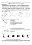
INSTALLATION
&OPERATION
MANUAL
6000 SERIES LIGHT BARSTM
TM
LOW PROFILE LIGHT BAR
Contents:
IMPORTANT:
Introduction ............................................................. 2
Unpacking&Pre-Installation ....................................... 2
Installation&Mounting ............................................... 3
SirenSpeakers ......................................................... 3
Hook-onMounting .................................................. 4
PermanentMounting ............................................... 5
Wiring Instructions .................................................. 6
Maintenance ............................................................ 7
PartsList(ReplacementParts/ExplodedView) ................ 8
Options ................................................................. 11
Specifications ......................................................... 11
Warranty ............................................................... 12
Readallinstructionsandwarningsbeforeinstallingandusing.
INSTALLER: Thismanualmustbedeliveredtotheenduserofthisequipment.
Introduction
All LP 6000 Series light bars include mounting kits, packed in a separate small box inside the box containing
the light bar. The standard kit may be used for hook-on or permanent mounting. Towing & Recovery bars,
normally pylon mounted, do not include mounting kits, however. These are optionally available from your dealer
or the factory.
!
WARNING!
The use of this or any warning device does not ensure that all drivers can or will observe or react
to an emergency warning signal. Never take the right-of-way for granted. It is your
responsibility to be sure you can proceed safely before entering an intersection, driving against
traffic, responding at a high rate of speed, or walking on or around traffic lanes.
The effectiveness of this warning device is highly dependent upon correct mounting and wiring.
Read and follow the manufacturer’s instructions before installing or using this device. The
vehicle operator should ensure daily that all features of the device operate correctly. In use,
the vehicle operator should ensure the projection of the warning signal is not blocked by vehicle
components (i.e.: open trunks or compartment doors), people, vehicles, or other obstructions.
This equipment is intended for use by authorized personnel only. It is the user’s responsibility
to understand and obey all laws regarding emergency warning devices. The user should check
all applicable city, state and federal laws and regulations.
Public Safety Equipment, Inc., assumes no liability for any loss resulting from the use of this
warning device.
Proper installation is vital to the performance of this warning device and the safe operation of
the emergency vehicle. It is important to recognize that the operator of the emergency vehicle
is under psychological and physiological stress caused by the emergency situation. The
warning device should be installed in such a manner as to: A) Not reduce the output
performance of the system, B) Place the controls within convenient reach of the operator so
that he can operate the system without losing eye contact with the roadway.
Emergency warning devices often require high electrical voltages and/or currents. Properly
protect and use caution around live electrical connections. Grounding or shorting of electrical
connections can cause high current arcing, which can cause personal injury and/or severe
vehicle damage, including fire. Do not touch the strobe light tubes, the strobe light head
assemblies or the strobe power supply while the system is in operation. Wait 10 minutes after
turning off the power from system before touching any internal components.
PROPER INSTALLATION COMBINED WITH OPERATOR TRAINING IN THE PROPER
USE OF EMERGENCY WARNING DEVICES IS ESSENTIAL TO ENSURE THE SAFETY OF
EMERGENCY PERSONNEL AND THE PUBLIC.
Unpacking & Pre-installation
Carefully remove the light bar from the shipping carton
and place on a flat surface, taking care not to damage
the wire cable coming out of the bottom. Examine the
unit for transit damage, cracked lenses, dented speaker
cover, etc. If convenient, you may wish to bench test
the unit before installing. Before applying voltage to the
bar, be sure you have read and understand the wiring
instructions attached to the cable. Standard LP6000TM
bars operate on 12 volt D.C. negative ground (earth)
systems only. If you have a positive ground (earth)
vehicle, or any other type of system, and have not
ordered a specially wired bar, contact the factory for instructions.
2
Installation & Mounting
Siren Speakers
NOTE! Use only speaker horns shaped specifically for the LP Light Bar (Z100, LP58 Speaker assemblies
or LPKIT Speaker Conversion Kit for use with a user supplied driver). Use of any other speaker horns will
obstruct the proper attachment of the speaker cover and void the warranty. It is generally easier to install
siren speakers before mounting the bar on the vehicle. No. 8 sheet metal screws will easily break through
the metallic tape and thread into the punched holes in the frame.
(647S (All 47" Light Bars with speaker center section))
Remove the stainless steel speaker cover by unscrewing the two screws at each end and lifting off. Using
the mounting holes indicated, mount either an LP58 or an Z100 speaker.
See Illustration 1 for hole locations. Connect the
speaker wires to the prewired terminal block and
replace the speaker cover.
655A (All 55" Light Bars)
Remove the stainless steel speaker
cover by unscrewing the two screws at
each end and lifting off. Using the
mounting holes indicated, mount either
one or two LP58 or Z100 speakers.
See Illustration 2 for hole locations.
Connect the speaker wires to the
prewired terminal block and replace the
speaker cover. When using two siren
speakers, follow speaker manufacturer’s
instructions for correct phasing of speakers. NOTE!
On all bars with speaker sections, after mounting
speaker(s), check to make sure that the cover clears
the speaker in the front and rear. If not, loosen the
mounting screws and reposition the speaker as
necessary. Improper mounting will bind the speaker cover and prevent the lenses from sealing correctly.
Sirens are an integral part of an effective audio/visual emergency warning system.
However, sirens are only short range secondary warning devices. The use of a siren
does not ensure that all drivers can or will observe or react to an emergency warning
signal, particularly at long distances or when either vehicle is traveling at a high rate of
speed. Sirens should only be used in a combination with effective warning lights and
never relied upon as a sole warning signal. Never take the right of way for granted. It is
WARNING! your responsibility to be sure you can proceed safely before entering an intersection,
SIRENPRODUCTS: driving against traffic, or responding at a high rate of speed.
The effectiveness of this warning device is highly dependent upon correct mounting and
wiring. Read and follow the manufacturer’s instructions before installing or using this
device. The vehicle operator should check the equipment daily to ensure that all features
of the device operate correctly.
To be effective, sirens must produce high sound levels that potentially can inflict hearing
damage. Installers should be warned to wear hearing protection, clear bystanders from
the area, and not to operate the siren indoors during testing. Vehicle operators and
occupants should access their exposure to siren noise and determine what steps, such
as consultation with professionals or use of hearing protection, should be implemented
to protect their hearing.
This equipment is intended for use by authorized personnel only. It is the user’s responsibility to understand and obey all laws regarding emergency warning devices. The user
should check all applicable city, state, and federal laws and regulations.
Public Safety Equipment, Inc., assumes no liability for any loss resulting from the use of
this warning device.
!
3
Proper installation is vital to the performance of the siren and the safe operation of the
emergency vehicle. It is important to recognize that the operator of the emergency
vehicle is under psychological and physiological stress caused by the emergency
situation. The siren system should be installed in such a manner as to: A) Not reduce the
acoustical performance of the system, B) Limit as much as practical the noise level in the
WARNING! passenger compartment of the vehicle, C) Place the controls within convenient reach of
SIRENPRODUCTS: the operator so that he/she can operate the system without losing eye contact with the
roadway.
Emergency warning devices often require high electrical voltages and/or currents.
Properly protect and use caution around live electrical connections. Grounding or
shorting of electrical connections can cause high current arcing, which can cause
personal injury and/or severe vehicle damage, including fire.
PROPER INSTALLATION COMBINED WITH OPERATOR TRAINING IN THE PROPER USE
OF EMERGENCY WARNING DEVICES IS ESSENTIAL TO ENSURE THE SAFETY OF
EMERGENCY PERSONNEL AND THE PUBLIC.
!
Hook-on Mounting
Begin the installation by attaching the rubber
feet to the mounting brackets using the 1/4"
bolts and acorn nuts provided. (See
Illustration 3;) do not install shims
at this time. Using a pad to
protect the roof of the vehicle,
place the light bar on the roof
and determine the correct
location of the bar and the best
pair of holes for attaching the
mounting tabs. Attach the
washers provided and one of
the three pairs of 1/4" mounting
holes supplied on each end of
the bar. (See Illustration 3 for
alternate hole locations.) Place
the bar on the vehicle
roof and attempt to
locate a position in
which the bar is level
fore and aft. If leveling
is required, install the
shim washers at this
time. (See Illustration 3.) If additional leveling is still needed, contact the factory for assistance. Lift each end
of the light bar and insert the 5/16-18 x 2-1/2" hex bolt from the back side. (See Illustration 3.) Install the
gutter hooks, lock washers, trim nuts, and tighten until secure. DO NOT OVERTIGHTEN: It is not necessary
to dimple the roof in order to achieve a secure and stable mount.
4
NOTE! The mounting brackets are slotted to allow
continuous adjustment from hole to hole. When the
brackets are installed, the rubber feet should rest as
close to the edge of the roof as possible; (See
Illustration 4.) Generally, with a 47" light bar, the
outboard set of holes would be used for all full
size and many intermediate size vehicles. The
tabs holding the rubber feet may be bent to
conform to the roof profile as shown in Illustrations
4 and 6. Some vehicles may require a slightly
longer or shorter mounting bolt. These are 5/16"
coarse thread bolts which can be obtained locally.
Permanent Mounting
Examine the roof of the vehicle to
determine the areas of greatest roof
strength as well as location of air horns,
etc. that will affect the location of the
light bar. Select the holes that will place the
mounting feet in the location selected and attach
the feet to the underside of the light bar, using the 5/16-18 thread forming bolts and 5/16" flat washers
provided. (See Illustration 5 for alternate hole location.) Attempt to locate a position in which the bar is
level fore and aft. If leveling is required, slide the shim washer under the appropriate tabs on the mounting
brackets.
(See Illustration 5.) If additional leveling is still needed, contact the factory for assistance. Once the bar is
level front to rear and centered side to side, mark the holes through the mounting tabs and remove the bar
from the vehicle. Drill out the mounting holes and remove any burrs. Attach the die cut rubber gaskets or
shims, if used. (See Illustration 5.) Remount the light bar and attach to the roof using four suitable fasteners
obtained locally. NOTE! The tabs on the mounting brackets may be bent at any angle to match the
curvature of the roof. (See Illustration 6.)
5
Wiring Instructions
!
WARNING!
Larger wires and tight connections will provide longer service life for components. For high
current wires, it is highly recommended that terminal blocks or soldered connections be used
with shrink tubing to protect the connections. Do not use insulation displacement
connectors (e.g. 3M® Scotchlock type connectors). Route wiring using grommets and
sealant when passing through compartment walls. Minimize the number of splices to
reduce voltage drop. High ambient temperatures (e.g. underhood) will significantly reduce
the current carrying capacity of wires, fuses, and circuit breakers. Use "SXL" type wire in
engine compartment. All wiring should conform to the minimum wire size and other
recommendations of the manufacturer and be protected from moving parts and hot
surfaces. Looms, grommets, cable ties, and similar installation hardware should be used to
anchor and protect all wiring.
Fuses or circuit breakers should be located as close to the power takeoff points as possible
and properly sized to protect the wiring and devices.
Particular attention should be paid to the location and method of making electrical
connections and splices to protect these points from corrosion and loss of conductivity.
Ground terminations should only be made to substantial chassis components, preferably
directly to the vehicle battery.
The user should install a fuse sized to approximately 125% of the maximum Amp capacity
in the supply line to protect against short circuits. For example, a 30 Amp fuse should
carry a maximum of 24 Amps. DO NOT USE 1/4" DIAMETER GLASS FUSES AS THEY
ARE NOT SUITABLE FOR CONTINUOUS DUTY IN SIZES ABOVE 15 AMPS. Circuit
breakers are very sensitive to high temperatures and will "false trip" when mounted in hot
environments or operated close to their capacity.
Route the wiring cable into the engine or passenger compartment, taking care to use grommets and `
to apply sealant around openings to keep water out. It is advisable to leave an extra loop of cable
when installing the light bar to allow for future changes or reinstallations. Connect the black lead to a
solid frame ground (earth), preferably the (-) or ground (earth) side of the battery and bring the other
wires to the control head or switches. Connect the wires to the control head or switch (as directed by
the wiring instructions on the cable). Next, calculate the light bar power draw. Table 1 consists of an
equation and data for quick calculating of light bar load. Run a power wire from the control head to
the (+) positive side of the battery, the alternator, or the stud on the battery side of the starter sole
noid. Use Table 2 for reference. Speaker Wires: If the light bar has a speaker section, the blue wires
go to the siren amplifier and are to be connected in accordance with the siren manufacturer’s instruc
tions. Test the unit for proper operation. CAUTION: Operating a siren with a live speaker can inflict
hearing damage -- always use hearing protection.
Remounting
When moving an LP 6000 bar from one vehicle to another, we suggest that new 5/16" mounting bolts
and rubber feet be used. These are standard hardware items that can usually be found at any hardware
store, or they can be ordered from the factory. The special hooks are stainless steel and should be
saved and reused.
NOTE! If different holes must be used to mount the brackets, tape over the unusual holes with duct
tape on the inside to prevent dirt and water from entering the light bar.
6
Maintenance
Lens Removal
First, remove the speaker cover by removing the four (4) hex head screws from the top of the
speaker cover. Next, remove the two (2) hex head screws on the top of the lens, followed by the two
(2) hex head screws on the outboard side of the lens. The lens can now be lifted off. If you have an all light
center section, the four (4) hex head screws holding the center lens to the pan have to be removed first,
then proceed with the lens screws.
Lamp Replacement
Remove the lens as outlined above. Next, inspect the bulb and compare to Illustration 7 to determine
bulb type. It may be necessary to remove any rotating or cylindrical filters to make access easier.
!
WARNING!
Lamps are extremely hot! Allow to cool completely before attempting to remove. Gloves
and eye protection should be worn when handling halogen lamps as they are pressurized
and accidental breakage can result in flying glass.
H-1: First, grasp bulb at base and turn until retaining clip is accessible. Using a blade screwdriver,
remove the retaining clip and pull bulb straight up. Grasp the power lead with long nose pliers and remove
the bulb. Replace with new bulb, insuring that the power lead is fully inserted into the bulb. Insert into the
rotator and ensure the retaining clip is fully inserted.
S-795 (Bayonet Style): Push down and turn to remove bulb. Install new bulb the same way.
General
Do not grease this unit. It is constructed with a permanently lubricated drive system which requires no
maintenance and can gum up if subjected to lubricants.
Lens Cleaning
Use plain water and a soft cloth, or Code 3® Lens polish and a very soft paper towel or facial tissue.
Because plastic scratches easily, cleaning is recommended only when necessary (about every six
months). Do not subject the lenses to car washes that use brushes, as these will scratch the lenses.
Frame Cleaning
To restore the aluminum to its original shine, run steel wool or an abrasive scrub pad along the length of
the frame, taking care not to scratch the lenses.
7
Parts List
Ref No. Description
1
#8 x 3/4" Pan Head Sheet Metal Screw
2
Speaker Cover
Part No. Qty.
T02933
--
- Regular
T08683
- Long
S91406
1
3
#8 x 3/4" Flat Head Sheet Metal Screw
T02918
4
4
Lens - Outboard - Green
S89725M
2
- Clear
S89721M
- Red
S89722M
- Blue
S89723M
8
Parts List
Ref No,
Description
Part No.
Lens - Outboard -Amber
S89724M
--
T00947
--
-Clear
T02901
--
-Red
T02902
--
-Blue
T02903
--
-Amber
T02904
--
-Din Blue
T02905
--
-Opaque
T02947
--
-Clear
S38171M
--
-Red
S38172M
--
-Blue
S38173M
--
-Amber
S38174M
--
-Din Blue
Lens - Center (for 47" bar)
Lens - Center (for 55" bar, 2 per bar)
5
#8 x 5/8" Hex Head Sheet Metal Screw
T02921
4
6
#8 x .270" Hex Head Sheet Metal Screw
T01215
6
7
Speaker Driver -100W
T00968
--
-58W
T00969
--
-LP58
T00625
--
S95977M
--
8
Rotating Reflector Assembly
9
S795 5OW 12V Bulb
T01540
--
H-1 55W 12V Bulb
T01543
--
10
H-1 Lamp Retaining Clip
T04933
--
11
Rotating Filter
-Red
S95989M
--
-Blue
S95990M
--
-Amber
S95991M
--
-Green
S95988M
--
9
Parts List
Ref No.
Description
Part No.
12
#8 x .270" Hex Head Sheet Metal Screw
13
Rotating Motor Ass--(Does not include Reflector Assy)
Qty.
T01215
--
Rotator Motor Assy 55W H-1 Std Speed
S95978M
--
Rotator Motor Assy 55W H-1 Fast Speed
S95979M
--
Rotator Motor Assy 50W Bayonet Std Speed
S95980M
--
Rotator Motor Assy 50W Bayonet Fast Speed
S95981M
--
Rotator Motor Assy 24V
S95982M
--
14
#8 x .270" Hex Head Sheet Metal Screw
T01215
--
15
#10 Machine Screw Washer
T00154
--
16
L.P. Half Mirror Module
S40002M
--
17
L.P. Speaker cover/lens Hold down Bracket
T00918
2
18
#8 x .270" Hex Head Sheet Metal Screw
T01215
--
19
L.P. Motor Assembly
See #13
--
20
L.P. Stationary Filter -Blue
T01280
--
-Amber
T01281
--
-Red
T01279
--
-Green
T01299
--
-(38")
S85145M
1
-Regular (47")
S85146M
--
-Long (55")
S85147M
--
S91474M
--
T00154
--
21
L.P. Frame
22
Speaker Bell
23
Speaker Mounting Screws
10
Parts Not Shown
50W Alley/Mini Takedown light module
S35205M
--
Center Lens Base Module
S38130M
--
L.P. Stingray Module
S40009M
--
L.P. Worklight
Options & Specifications
Many options are available for the LP 6000. This section is designed to describe the function of, and maintenance for, the various LP 6000 options.
STINGRAY - The StingRay is a modified rotating lamp which produces a patented three-mode signal that (1)
oscillates to the rear, (2) rotates conventionally, and (3) oscillates to the front. Lamp and reflector maintenance is the same as for a typical rotating lamp.
ALLEY LIGHTS - Located at each end of the light bar, to provide light to the side of the vehicle. This smaller
unit is held in a metal bracket that is attached to the frame with 2 screws.
HIGH SPEED ROTATING LAMPS - A rotating lamp that produces twice as many flashes as a conventional
assembly. The only significant differences between this unit and a normal assembly are that a faster motor is
used. Maintenance is the same as for a typical rotating lamp.
STOP/TURN/TAIL LIGHTS - Located in the light bar facing rear, one on the driver side, one on the passenger side, these lights provide stop, turn, and tail signals to following traffic when connected to the vehicle
lighting system. Bulbs used are an 1157 bayonet type.
D.O.T. LIGHTS - A set of three marker lights as required by the Department of Transportation for truck
application. Bulbs are wedge base "194" type.
FLASHER - The Table below shows the different models and their functions.
FEATURES
100W (2 lights),
Alternating Flash
FLASHER TYPE
360RS 360RD 360RDK
X
200W (4 lights),
Alternating flash
rear only or front
& rear
200W (4 lights),
Alternating flash,
rear only, front &
rear, or steady burn
front/rear flash
X
700
X
710/711
X
X
200W Heavy duty
Alternating flash
X
200W Heavy duty
Programmed flash
X
X
11
WARRANTY
Code 3, ®Inc.'s emergency devices are tested and found to be operational at the time of
manufacture. Provided they are installed and operated in accordance with manufacturer's
recommendations, Code 3, Inc. guarantees all parts and components except the lamps to a period
of 1 year (unless otherwise expressed) from the date of purchase or delivery, whichever is later.
Units demonstrated to be defective within the warranty period will be repaired or replaced at the
factory service center at no cost.
Use of lamp or other electrical load of a wattage higher than installed or recommended by the
factory, or use of inappropriate or inadequate wiring or circuit protection causes this warranty to
become void. Failure or destruction of the product resulting from abuse or unusual use and/or
accidents is not covered by this warranty. Code 3, Inc. shall in no way be liable for other damages
including consequential, indirect or special damages whether loss is due to negligence or breach of
warranty.
CODE 3, INC. MAKES NO OTHER EXPRESS OR IMPLIED WARRANTY INCLUDING, WITHOUT LIMITATION, WARRANTIES OF FITNESS OR MERCHANTABILITY,
WITH RESPECT TO THIS PRODUCT.
PRODUCT RETURNS
If a product must be returned for repair or replacement*, please contact our factory to
obtain a Return Goods Authorization Number (RGA number) before you ship the product to
Code 3, Inc. Write the RGA number clearly on the package near the mailing label. Be sure you
use sufficient packing materials to avoid damage to the product being returned while in transit.
*Code 3, Inc. reserves the right to repair or replace at its discretion. Code 3, Inc. assumes no responsibility or liability for expenses incurred
for the removal and /or reinstallation of products requiring service and/or repair.; nor for the packaging, handling, and shipping: nor for the handling of
products return to sender after the service has been rendered.
NEED HELP? Call our Technical Assistance Hotline - (314) 996-2800
Code 3, Inc.
10986 N. Warson Road
St. Louis, Missouri 63114-2029—USA
www.code3pse.com
Code 3 is a registered trademark of Code 3, Inc.,a subsidiary of Public Safety Equipment, Inc.
12
Revision 7, 12/2005- Instruction Book Part No. T00929
©2004-5 Code 3, Inc. Printed in USA