1
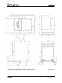
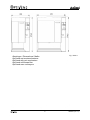
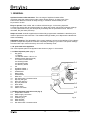
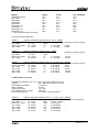
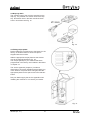
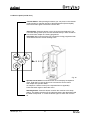
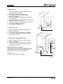
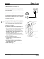
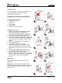
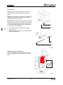
Choco 1 2 3 4 1 TS /TL 2 TS 3 TS 4 TS HS User manual 1.1 1.2 1 2.1 2.2 2.3 2 2.4 3 4 5 6 7 13 8 9 14 10 15 11 16 12 Fig. / Abb. 1 2 08/2009 (rev. 6.1) Afmetingen / Dimenstions / Maße: OptiVend CHOCO, 1 & 2 08/2009 (rev. 6.1) 3 Fig. / Abb. 2. Afmetingen / Dimenstions / Maße: OptiVend 3 & 4 4 Fig. / Abb. 3. 08/2009 (rev. 6.1) Afmetingen / Dimentions / Maße: OptiVend TS (Thermos Small): 1 TS, 3 TS, 4 TS, HS TL (Thermos Large): 1 TL 08/2009 (rev. 6.1) 5 Fig. / Abb. 4. Fig. / Abb. 5. Afmetingen / Dimenstions / Maße: OptiVend met muntmechanisme OptiVend with coin mechanism OptiVend mit Munzprüfer OptiVend avec monnayeur 6 08/2009 (rev. 6.1) TABLE OF CONTENT Purpose of the appliance....................................................................................................................... 10 Safety instructions and danger warnings .............................................................................................. 11 Safeguards ............................................................................................................................................ 12 Appliances and the environment ........................................................................................................... 13 1. GENERAL ......................................................................................................................................... 14 1.1.1 Most important parts (fig. 1) ................................................................................................... 14 1.1.2 Most important parts mixer unit (fig. 6).................................................................................... 14 2. TECHNICAL DETAILS ...................................................................................................................... 15 2.1 Multi phase execution ................................................................................................................. 16 2.2 OptiVend HS (High Speed) execution ........................................................................................ 17 3. INSTALLATION ................................................................................................................................. 18 3.1 Unpacking ................................................................................................................................... 18 3.3 Water connection ........................................................................................................................ 19 3.3 Water connection ........................................................................................................................ 19 3.3.1 Water treatment (fig. 8) ........................................................................................................... 19 3.3.2 Stand-alone pump set (fig. 9).................................................................................................. 19 3.4 Electrical connection ................................................................................................................... 20 3.5 Drip tray drain.............................................................................................................................. 21 3.6 Fitting recipe plates ..................................................................................................................... 21 3.7 Standard recipe settings ............................................................................................................. 22 3.7.1 OptiVend 5 buttons.................................................................................................................. 22 3.7.2 OptiVend 10 buttons................................................................................................................ 23 3.8 Filling the ingredient holders ....................................................................................................... 24 3.9 Positioning................................................................................................................................... 25 4. FIRST USE........................................................................................................................................ 25 4.1 First time use / flushing the boiler system................................................................................... 25 4.2 First settings operator/service menu........................................................................................... 25 5. KEY PANEL....................................................................................................................................... 26 5.1 Key panel (front).......................................................................................................................... 26 5.2 Service panel (inside door) ......................................................................................................... 27 6. MENU STRUCTURE......................................................................................................................... 28 6.1 The user menu ............................................................................................................................ 28 6.2 The operator menu...................................................................................................................... 29 7. DAILY USE........................................................................................................................................ 30 7.1 How to fill the ingredient holders................................................................................................. 30 7.2 Preparations................................................................................................................................ 31 7.3 Preparing a cup........................................................................................................................... 31 7.4 Preparing a Jug (OptiVend TS/TL) ............................................................................................. 31 7.5 Paid vending coin mechanism (optional) ................................................................................... 32 7.6 Automatic blocking functions....................................................................................................... 32 7.6 Manual blocking functions (fig. 29) ............................................................................................. 33 8. MAINTENANCE ................................................................................................................................ 33 8.1 Cleaning programme................................................................................................................... 33 8.2 Mixer system ............................................................................................................................... 34 8.3 Canister(s)................................................................................................................................... 35 8.4 Drip tray....................................................................................................................................... 36 8.5 Housing ....................................................................................................................................... 36 8.6 Cleaning interval ......................................................................................................................... 36 9. SERVICE MOMENT.......................................................................................................................... 37 10. TEMPERATURE SAFEGUARD...................................................................................................... 38 11. TRANSPORT / STORAGE.............................................................................................................. 38 12. TROUBLESHOOTING .................................................................................................................... 39 13. CONSUMER ACCESSORIES ........................................................................................................ 40 08/2009 (rev. 6.1) 7 © 2007 Animo® All rights reserved. No part of this document may be reproduced and/or publizised by means of printing, microfilm, electronic or any other means whatsoever without the prior written permission of the manufacturer. This also applies to the accompanying drawings and/or diagrams. Animo reserves the right to change parts at any time without giving prior or direct notification to the customer. The content of this manual can also be changed without prior notification. This manual covers the standard model of the appliance. Animo can therefore not be held liable for any losses arising from the fact that the specifications of the appliance supplied to you deviate from the standard model. Please contact your supplier’s service department for information concerning adjustment, maintenance or repairs not covered by this manual. Although this manual was produced with the greatest possible care, the manufacturer is unable to accept liability for errors in this document or their consequences. You are advised to carefully read the instructions in this document: they contain important information about safety when installing, using and maintaining the appliance. Keep this document in a safe place so that you can consult it when necessary. PREFACE Purpose of this document This document serves as a manual that enables qualified personnel to safely install, program and maintain the appliance. - 'Qualified personnel' are defined as people that can program the appliance, perform maintenance on it and repair minor faults. All chapters and paragraphs are numbered. The various illustrations to which the text refers are given in the fold-out sheets or at the back of this booklet or under the particular subjects. Icons and symbols NOTICE General instructions for: IMPORTANT, NOTE or REMARK. CAUTION ! Warning of possible damage to the appliance, the surroundings or the environment. WARNING Warning of possible serious damage to the appliance or physical injury. WARNING Warning of electricity hazard. 8 08/2009 (rev. 6.1) Models This manual covers the following appliances: OptiVend Choco OptiVend 1 OptiVend 2 Coin mechanism (option) OptiVend 3 OptiVend 4 Coin mechanism (option) OptiVend 1 TS OptiVend 3 TS OptiVend 4 TS OptiVend HS OptiVend TL 1 08/2009 (rev. 6.1) 9 Purpose of the appliance The sole purpose of this appliance is to make hot drinks. The use of the appliance for other purposes is not permitted and may be hazardous. The manufacturer cannot be held liable for losses caused by using the appliance for purposes other than those indicated here or by incorrect use. Service and technical support Please contact your dealer for information not given in this document regarding specific adjustment, maintenance and repairs. Before contacting your dealer you should note the following appliance details, marked with a #. You will find these details on the type plate attached to your appliance. A - Type # B - Article number # C - Machine number # D - Supply voltage E - Frequency F - Output Guarantee conditions The guarantee conditions applicable to this appliance are an integral part of the general terms of delivery. Directives This appliance meets the following requirements: EMC 92/31/EEG & 93/68/EEG LVD 73/23/EEG. RoHs 2002/95/EEG WEEE 2002/96/EEG FOOD 1935/2004/EEG 10 08/2009 (rev. 6.1) Safety instructions and danger warnings This appliance meets the mandatory safety regulations. Inexpert use can result in personal injury and material damage. The following warnings and safety instructions must be observed before using the appliances. Instructions for use Read these instructions for use carefully, before using this appliance. This will protect your safety and prevent damage being caused to the appliance. Perform the various actions in the order given. Always keep this manual close by the appliance. Installation • Place the appliance at buffet height and on a firm, level base, in such a way that it can be connected to the water and power supply. • Connect the appliance to an earthed wall socket. • Position the appliance in such a way that no damage can be caused if it leaks. • Do not tilt the appliance, always position and move the appliance upright. • Water always remains in the heating system: for this reason the appliance must not be placed in an area where the temperature can fall below freezing point. • When installing the appliance, always observe the local rules and use approved materials and parts. • The ‘Installation’ chapter must again be followed when repositioning the appliance. Use • Inspect the appliance before using it and check it for damage. • Never submerge or spray the appliance. • Do not press the buttons with a sharp object. • Protect the controls against dirt and grease. • It is advisable to take the plug out of the socket and close the water tap if the appliance is not going to be used for longer periods of time. Maintenance and troubleshooting • Overdue maintenance to the heating system can result in high repair costs and annulment of the guarantee. • Do not leave the appliance unattended when maintenance is being performed. • Always have repairs carried out by a qualified service engineer. • The plug must be taken out of the socket if the appliance has to be opened for cleaning or repairs. • The manufacturer cannot be held liable for losses caused as a result of failure to observe these safety instructions. 08/2009 (rev. 6.1) 11 Safeguards The appliance is fitted with the following safeguards: Dry-boil protection (fig.1-13) The appliance is equipped with a temperature safeguard that can be accessed externally. It is located at the backside of the appliance (fig. 1-13). This safeguard shuts down the heating element if the temperature gets high. The most common cause of the dry-bold protection tripping is failure to descale the machine in time. If the display shows the text F2 Heating, See chapter 10. Temperature safeguard. On/off switch (fig. 1-8) The on/off switch is used to switch the appliance on and off. Remember that the appliance can still be activated after switching it off! For this reason you should always remove the plug from the socket to render the appliance voltage-free. Emergency stop multicup (Jug) The dispensing of a jug recipe is stopped simply by pressing any recipe button. The selected jug recipe is then cancelled and one more cup is dispensed. Warning indication display (fig. 1-1) In the event of a technical malfunction the display will report an error code (eg. E1). If this occurs see chapter 12. Troubleshooting. Drip tray full signal (optional) When the drip tray is full, this is indicated on the display [F1 drip tray full] and the control panel is blocked. When the drip tray has been emptied the message in the display disappears automatically and the control panel is unblocked. Model • • • • • • • • • • • • modern appearance stainless steel housing soft key operating panel with display microprocessor control cleaning programme energy saving programme with manual and programmable standby time Cup counter open boiler system with dry-boil protection electronic level regulator and temperature regulation preventive service moment signal for operator external water tank (optional) coin mechanism (optional) 12 08/2009 (rev. 6.1) Materials All components inside the appliance that come into contact with foodstuffs are made of stainless steel, foodstuff resistant silicons and polysulphone. Temperature monitoring An electronic temperature monitoring system guarantees the constant quality of the end product. Accessibility The need to carry out maintenance easily was taken into account when constructing the appliance. This resulted in easy access to all important parts. Control system The control systems are designed in such a way that, if necessary, the systems can be exchanged by a qualified engineer. This can be done on-site. Programming A clearly laid-out menu system is installed, so that there is no need for an external programming module. Low voltage For safety reasons, all internal current users - apart from the heating element - are powered with 24 VDC low voltage. Appliances and the environment The packing material Your new machine has been carefully packaged to protect it against damage. The packing is not harmful to the environment and consists of the following materials: • Corrugated cardboard • Filler elements made of polyurethane foam <PUR> covered with a polythene film (>PE-HD<). The waste processing plant in your municipality will be pleased to inform you where you can dispose of the materials. Discarding the appliance No appliance lasts forever. When the time comes to discard your appliance it will usually be possible to return it to your dealer. If this is not the case, ask your municipal council about the alternatives for recycling the materials. All plastic parts have been given standard codes. The parts of the appliance such as the printed circuit board and accompanying parts form electrical and electronic waste. The metal body is made of stainless steel and can be completely dismantled. 08/2009 (rev. 6.1) 13 1. GENERAL OptiVend instant coffee machines. The new range of OptiVend instant coffee machines meets the needs of the modern coffee drinker perfectly. A single push of the button and a delicious hot drink is ready to enjoy in moments. And an entire pot can be poured in no time. Easy to operate. Fresh coffee, with or without milk and sugar. A nice strong espresso. A cappuccino with a thick and creamy head. Or a tasty cafe crème, cafe au lait or Wiener melange. You can prepare almost any hot drink quickly and easily with an OptiVend machine. Also hot chocolate, tea (hot water) and soup. Simple to install. Animo® supplies the machines fully programmed. Installation is therefore just a matter of placement and connection. The standard settings enable you to dispense the tastiest hot drinks immediately. Adjustable settings. The adjustability of the control settings is unique to the OptiVend. This makes it possible to adjust the recipes for hot drinks completely according to your taste. The specific settings are saved with a pin code so that they can not be ‘accidentally’ reset. 1.1 A quick look at the appliance The most important parts of the appliance are shown on page 1 in this manual. 1.1.1 Most important parts (fig. 1) 1. Key panel 1.1 Display 1.2 Selection button 1 till 5 or 10 2. Operator panel (Service panel) 2.1 Product counter button 2.2 Cleaning button 2.3 Operator button 2.4 Stand-by button 3. Lid 4. Ingredient holder 1 5. Ingredient holder 2 6. Outlet bends 7. Rating plate 8. On/Off switch 9. Mixer unit 10. Hot drink outlet / Hot water outlet 11. Drip tray with grid 12. Door lock with key 13. Dry boil protection 14. Drain boiler 15. Power cable 16. Water connection 9.1 9.2 9.3 9.4 9.5 9.6 1.1.2 Most important parts mixer unit (fig. 6) 9.1 Evaporation extractor 9.2 Water supply connection 9.3 Mixer motor shaft 9.4 Fastening ring 9.5 Mixer impellor 9.6 Mixer housing 9.7 Hot drink outlet / Hot water outlet 9.7 Fig. 6 14 08/2009 (rev. 6.1) 2. TECHNICAL DETAILS Model OptiVend CHOCO 1 2 3 4 1 TS 1 TL 3 TS 4 TS Capacity Hour capacity per cup 120ml Dosing time per cup 120ml Dosing time per jug Hour capacity hot water Boiler contents 2,5 litre Heating time boiler 360 cups approx. 7 sec. see table 1 approx. 40 litre 2,5 litre 4 min. 360 cups approx. 7 sec. see table 2 approx. 40 litre 5,5 litre 8,5 min. 360 cups approx. 7 sec. see table 3 approx. 40 litre 5,5 litre 8,5 min. Water system Water hardness Water conductivity Water connection Water temp. adjust Min. - Max. water pressure Flow pressure min. 5°dH (100 mg CACO3/l) ≥ 70 µ Siemens/cm 3/4" external gas thread 70 - 97 °C 0,2 MPa (2 bar) - 1 MPa (10 bar) ≥ 6 l. / min. Electrical system Voltage / frequency Total output Rating heating element Fuse Safety class Internal circuit Location type plate 1N~ 220-240V 50-60Cy 3275W 3200W 16 A I 24VDC (direct current) above the On/Off switch Materials Housing / Door Boiler Drip tray Stainless steel 18/9 (1.4301) (AISI 304) Stainless steel 18/10 (1.4401) (AISI 316) Plastic <PS> black Dimensions 08/2009 (rev. 6.1) OptiVend Choco, 1 & 2 OptiVend 3 & 4 OptiVend 1TS/TL, 3TS, 4TS, HS OptiVend coin mechanism 15 Page 3 Page 4 Page 5 Page 6 Weight OptiVend CHOCO OptiVend 1 OptiVend 2 OptiVend 3 OptiVend 4 OptiVend 1 TS OptiVend 1 TL OptiVend 3 TS OptiVend 4 TS * = full ingredient holders and boiler Empty 16.2 16.2 16.5 22.3 22.3 23.0 24.4 24.6 25.0 Filled* 21.7 19.5 18.4 31.3 32.4 29.5 31.0 33.6 35.1 Incl. packaging 19.0 19.0 19.3 25.9 25.9 26.6 28.0 28.2 28.6 Subject to technical alteration TABLE 1 capacity information Optivend Choco, 1 & 2 - 3200W Dosing (Coffee) Dosing time number at ones Cup 120ml ca.7 sec. 360x Little jug 2x 120ml ca. 12 sec. 5x (= 10 Cups) Jug 1,2 litre ca. 50 sec. 1x (= 10 Cups) Recovery time max. dosing 64 sec. 62 sec. TABLE 2 capacity information Optivend 3 & 4 - 3200W Dosing (Coffee) Dosing time number at ones Cup 120ml ca.7 sec. 360x Little jug 2x 120ml ca. 12 sec. 7x (= 14 Cups) Jug 1,2 litre ca. 50 sec. 1x (= 10 Cups) Recovery time max. dosing 131 sec. 30 sec. TABLE 3 capacity information Optivend 1TS / TL, 3 (TS), 4 (TS) - 3200W Dosing (Coffee) Dosing time number at ones Recovery time max. dosing Little jug 2x 120ml ca. 12 sec. 11x (= 22 Cups) 4 sec. Jug 1,2 litre ca. 50 sec. 2x (= 24 Cups) 80 sec. Jug 1,5 litre ca. 60 sec. 2x (= 25 Cups) 95 sec. Jug 2,0 litre ca. 80 sec. 1x (= 16 Cups) 125 sec. Jug 2,2 litre ca. 90 sec. 1x (= 18 Cups) 138 sec. 2.1 Multi phase execution Available for OptiVend 1 TS / TL, 3 (TS), 4 (TS) only (more over price) Voltage 2N~ 380-415V / 50-60Cy / 6475W Hour capacity hot water ca. 80 litre Boiler contents 5,5 litre Heating time boiler ca. 5 min. Hour capacity per cup 120ml 665 cups Hour capacity per jug ca. 40 sec. / litre (see table 4) TABLE 4 capacity information Optivend 1TS / TL, 3 (TS), 4 (TS) - 6400W Dosing (Coffee) Dosing time number at ones Recovery time in between Cup 120ml ca. 7 sec. 665x (= 80 l/h : 120ml) Little jug 2x 120ml ca. 12 sec. 240x (= 480 Cups) Jug 1,2 litre ca. 50 sec. 73x (= 730 Cups) Jug 1,5 litre ca. 60 sec. 53x (= 662 Cups) Jug 2,0 litre ca. 80 sec. 44x (= 733 Cups) Jug 2,2 litre ca. 90 sec. 40x (= 733 Cups) - 16 08/2009 (rev. 6.1) 2.2 OptiVend HS (High Speed) execution Properties: • Standard executed with two large containers • Parallel dosing - “a bisection” of the dosing speed in comparison with a standard OptiVend Technical specifications Article number Hour capacity hot water Boiler Stainless steel Heating time boiler Hour capacity cups (120 ml) Dosing time Electrical connection Water connection Dimensions (W x D x H) Dispensing height purchase (coffee) Cup 120ml Kannetjes 2 x 120ml Jug 1,2 litre Jug 1,5 litre Jug 2,0 litre Jug 2,2 litre 10482 118 litre 5,5 litre 3 min. 915 cups 5 sec 3N~ 380-415V / 50-60Hz / 9675W ¾” 389 x 515 x 697 mm. 235 mm Dosing speed: approx. 5 sec. approx. 9 sec. approx. 40 sec. approx. 50 sec. approx. 66 sec. approx. 72 sec. At one Time: 720x (= 86 litre/hour) 400x (= 800 cups) 90x (= 900 cups) 72x (= 900 cups) 54x (= 900 cups) 50x (= 916 cups) Recipe plate ● = optie Coffee 1 Coffee 2 Coffee creme Espresso 3 Espresso ● Double espresso ● chocolate Decaf 4 Hot Water ● Soup ● Hot milk Coffee milk Filling the reservoirs: This model has two large containers; nr.1 (left) & nr.3 (right). Because of the parallel dosing methode both containers should be filled with the same amount of the same ingredient. Coffee sugar Coffee milk & sugar Espresso sugar Coffee chocolate Espresso chocolate Cappuccino Ingredient capacity Wiener Melange Volume 4,7 ltr. Moccacino Coffee: 800 gr. = 550 cups à 120ml HS Coffee Cappuccino sugar Coffee ● Tea 7 Hot Water 8 Hot Water ● Hot Water 5 Coffee 6 Coffee 08/2009 (rev. 6.1) 17 3. INSTALLATION This appliance may only be positioned and connected by a qualified service engineer. The following rules must be observed: • • • only suitable for indoor use not suitable for use in humid areas not suitable for areas with explosion hazard 3.1 Unpacking The machine has been carefully packed to prevent damage being caused to your new appliance. Remove the packing carefully without using sharp objects. To protect the stainless steel-parts and the blue photographic display from scratches these surfaces are temporary protected by a foil. This foil must be removed during installation Check if the appliance is complete. The appliance is delivered with the following accessories: Measuring cup 0,25L Drip tray + grid Coffee-deposit solvent (sachet) Brush Door keys User manual Service annex Label set Drain hose (drip tray) 1,5m connection hose Number 1 1 1 1 2 1 1 2 1 1 Please contact your dealer in case parts are missing or damaged. WARNING Water always remains in the heating system: for this reason the appliance must not be placed in an area where the temperature can fall below freezing point. 3.2 Preparation for positioning • Place the appliance at buffet height on a firm, level base that can withstand the weight of the machine when filled. • Make sure that the appliance is level and placed somewhere where it will not cause damage should leakage occur. • Position the appliance in such a way that the ventilation slots are not obstructed by the rear wall. • The water supply line and the power connection must be within half a metre of where the machine is positioned. • The user is responsible for ensuring that these technical installation preparations are executed according to local regulations by qualified engineers. • The service engineer is only permitted to connect the appliance to the prepared connection points. 18 08/2009 (rev. 6.1) 3.3 Water connection The system must be fitted with a stopcock, a drain, a non-return valve and must end with an easily accessible aeration tap with a 3/4" connector. The minimum water pressure must not fall below 1 bar (with 5 l./min. flow pressure). The Optivend can be connected to hot water if necessary. We expressly recommend the use of a special hot water hose (fig. 7) for this purpose. • Warm water connection hose Art. No. 08175. 60°C Fig.7 3.3.1 Water treatment (fig. 8) You are emphatically advised to use a water softener and/or a water filter if the water contains too much chlorine or is too hard. This enhances the quality of the drink and precludes having to descale the appliance too often. • Filter system Brita AquaQuell 1.5 Art. No. 99681 Incl. Hose set + Filter cartridge • Brita AquaQuell 1.5 Art. No. 07996 Fig. 8 3.3.2 Stand-alone pump set (fig. 9) If there is no water connection in the vicinity, it can be supplied with an optional stand-alone pump set. • Pump set • Water bottle 18 litre Art. No. 93500 Art. No. 01013 3.3.3 Bottom cabinet (fig. 10) A bottom cabinet is available as an option. Standard suitable for the Optivend Choco, Optivend 1 and 2. With top leaf suitable for Optivend 3 and 4. The bottom cabinet is constructed ready for the building in of the stand-alone pump set and a water filter on the back. • Bottom cabinet Art. no. 03043 • Top leaf Art. no. 03044 Fig. 9 Fig. 10 08/2009 (rev. 6.1) 19 3.4 Electrical connection WARNING Supply voltages and frequencies can differ per country. Check if the appliance is suitable for connection to the local power mains. Check if the details on the type plate (fig. 11) correspond. Connect the appliance to an earthed wall socket. The earthed wall socket and the fused group with a main switch belong to the electrical installation. No heavy machines that could cause variations in power when being switched on, can be connected to this group. A machine with power current (three phase) is delivered from the factory without plug. At delivery, the machine must be provided with an electrically suitable plug as advised and provided by the installer. Depending on the appliance's electrical set-up, it must be connected as below. (fig. 12) (fig. 13) (fig. 14) (fig. 15) 1 N~ 2 N~ 3 N~ 3 ~ 230V 400V 400V 230V Fig 11 Fig 12 (3-core cable). (4-core cable). (5-core cable). (4-core cable). The following points should be observed when wiring a new plug: Fig 13 1. The GREEN/YELLOW colored wire [ EARTH ] should be connected to the terminal which is either marked with the letter [ PE ], the "earth" symbol ( ), or colored green/yellow. 2. The BLUE colored wire [ NEUTRAL ] should be connected to the terminal which is either marked with the letter [ N ] or colored black. Fig 14 3. The BROWN, BLACK and GRAY colored wire [ PHASE ] should be connected to the terminal which is either marked with the letter [ L1, L2 and L3 ]. The supplier cannot be held liable for any consequences arising from failure during installation of the appliance according to the instructions. 20 Fig 15 08/2009 (rev. 6.1) 3.5 Drip tray drain The overflow hose of the machine empties into the drip tray. It is possible to fit a drain hose to the drip tray. Drill a drain hole in the back and fit the drain hose in accordance with fig. 16. Fig. 16 3.6 Fitting recipe plates Recipe plates are not fitted next to the buttons in the factory. A standard sheet of various recipes is supplied with the machine. Slide the appropriate recipe plate into the window next to the appropriate button (fig. 16). The recipes (drinks) for your machine that were programmed in the factory are included in the tables in chapter 3.7. The service appendix (chapter 3) includes a description of how each individual recipe (drink) Jug is set. When a recipe has been changed, slide the appropriate plate into the space next to the relevant button. Did your dealer supply the service appendix when installing the machine? If not contact your dealer. Fig. 17 08/2009 (rev. 6.1) 21 3.7 Standard recipe settings 3.7.1 OptiVend 5 buttons Number of ingredientholders 1 2 3 4 5 I 1 2 ● = optional I II Recipe plate 1 2 3 ● ● 1 2 3 1 2 4 ● ● ● ● ● ● ● 4 5 ● ● ● ● ● ● ● ● ● ● ● ● ● COFFEE COFFEE CREME ESPRESSO HOT CHOCOLATE HOT CHOCOLATE HOT CHOCOLATE COFFEE CHOCOLATE HOT WATER COFFEE MILK COFFEE SUGAR ESPRESSO SUGAR DOUBLE ESPRESSO WIENER MELANGE CAPPUCCINO ESPRESSO CHOCOLATE DECAF TEA HOT MILK SOUP COFFEE HOT WATER Table 5 22 08/2009 (rev. 6.1) 3.7.2 OptiVend 10 buttons Number of ingredientholders 3 4 III IV 1TL 1TS 3TS 4TS ● = optional I I III IV 1 2 3 1 2 3 4 5 6 7 8 9 10 ● 4 ● 8 ● ● ● ● 1 5 7 ● ● 6 ● 10 ● ● 2 3 4 ● 7 ● 8 ● 9 ● ● ● ● ● 5 ● 6 1 2 1 2 3 ● ● 3 ● ● 4 ● ● 4 ● ● 1 1 2 ● 3 ● 7 ● ● ● ● ● ● 5 ● 8 ● ● 2 3 4 ● 6 4 ● 5 ● 7 8 ● 5 6 ● 7 8 ● 5 6 Recipe plate COFFEE COFFEE COFFEE CREME ESPRESSO ESPRESSO DOUBLE ESPRESSO CHOCOLATE DECAF HOT WATER SOUP HOT MILK COFFEE MILK COFFEE SUGAR COFFEE MILK & SUGAR ESPRESSO SUGAR COFFEE CHOCOLATE ESPRESSO CHOCOLATE 6 ● ● 8 ● 7 ● ● ● ● 9 ● 9 10 CAPPUCCINO CAPPUCCINO SUGAR WIENER MELANGE TEA HOT WATER HOT WATER HOT WATER COFFEE COFFEE Table 6 08/2009 (rev. 6.1) 23 3.8 Filling the ingredient holders Fill the ingredient holder(s) with the ingredient according below table (3). 1 1. 2. 3. 4. 5. 2 6. Open the lid (fig. 18-1) of the appliance. Pull the holder forwards out of the appliance. Turn the outlet bend horizontally (fig. 18-3). Fill the holder with the correct ingredient (fig. 18-4). Replace the holder(s) in the correct order. Make sure that the holder's drive bush fits over the cog in the rear partition (fig. 18-5). Turn the outlet bend back into the correct position (fig. 18-6). 3 4 Ingredient capacity Volume 4,7 litre. Cacao: 3000 gr. / 150 cups 120ml Choco Cacao 1 1 TS 1 TL Volume 4,7 litre. Coffee 1000 gr. / 685 cups 120ml 5 Coffee Volume 2,35 litre. Coffee: 500 gr. / 345 cups Cacao: 1350 gr. / 68 cups 2 Coffee Cacao 3 3 TS Coffee Topping Cacao 4 4 TS Coffee Sugar Topping Cacao Table 7 6 Fig. 18 24 08/2009 (rev. 6.1) 3.9 Positioning 1. Position the appliance level in the workplace where it is intended to serve. 2. Keep at least 7 cm free to the right of the appliance so that the door (fig. 2 - 4) can be opened. 3. Keep at least 22 cm free above the appliance so that the lid (fig.2-4) can be fully opened. 4. Check if the specifications given on the rating plate (fig. 1-7) correspond to the mains voltage. 5. Connect the appliance to the water supply (fig. 1-16) using the connection hose supplied. 6. Close the door and place the drip tray under the outlet (fig.1-11). 7. It is possible to connect a drain to the drip tray (chapter 3.5, fig.16). There is a nozzle on the back side of the drip tray. Drill through it and connect the drain. 8. The appliance can now be put into operation. 4. FIRST USE The instructions given in chapter 3. INSTALLATION must be carried out before the new appliance can be put into operation. • When used for the first time the appliance works according to the standard factory settings. • The various settings can be altered by trained, authorized personnel. Refer to the separate service appendix, chapter 2.3 The service menu. This chapter will explain the coffee brewing and hot water system process: when the appliance is used for the first time. when the appliance has not been used for more than 1 week, for example after a holiday period. 4.1 First time use / flushing the boiler system 1. Open the water tap and check if the swivel connections are not leaking. 2. Put the plug in an earthed wall socket. 3. Turn on the appliance using the switch (fig. 1-8), the display (fig. 1-11) lights up and you will hear a beeping sound. 4. In the display first appears the text: [ F3 Filling ] and than [ F2 Heating ]. During the warm-up phase, the settings can be adjusted as indicated in chapter 4.2. 5. After approximately 4 minutes (OV 3&4; 8,5 min.) the appliance will have heated up and the following text will appear: [ Make your choice . . . ]. 6. Place an empty cup with a minimum content of 120 ml (fig. 1-10) under the outlet and select your drink. 7. Discard the first 2 cups of each drink selection. 8. Make another selection and check if the flavour and quantity are correct, repeat this for each drink. Are the flavour and quantity correct? If so, the appliance is ready for use. 9. If the flavour or quantity are not correct, see the separate Service enclosure: 3. Recipe settings 4.2 First settings operator/service menu The following details are set in the service menu immediately after being used for the first time. Please note: The default language setting is English. To gain access to the service menu (PIN-code) see chapter 2.2 of the service enclosure • • • 2.2 System settings 2.2.3 Language 2.3 Time (actual time) 2.8 Descaling / filter 2.8.0 Service moment (Descale counter / filter counter) You can study the remaining operator menu settings later. The appliance is now ready for use. 08/2009 (rev. 6.1) 25 5. KEY PANEL The appliance is executed with two operating panels. • The key panel on the front of the door (fig. 1-1) is mainly for daily use. • The service panel in the inside of the door (fig. 1-2) is only mentioned for the operator to get access to the operator- and service menu (only after entering a PIN-code). CAUTION • Never press de buttons with a sharp object. • Protect the controls against dirt and grease. 5.1 Key panel (front) The control panel contains a number of SOFT buttons and a illuminated display. Display; this activates when the machine is switched on. The display provides users with information on the setting of the machine. Selection buttons: these are set in the factory as specified in the tables in chapter 3.7. RECIPE 1 RECIPE 2 RECIPE 3 RECIPE 4 RECIPE 5 The top four selection buttons have a second function in addition to their basic function after the operator menu and/or service menu has been activated. It is possible to set every button for a different drink option. The service appendix (chapter 2.3) describes how each individual recipe (drink) Jug is set. When you set a different recipe, slide the appropriate plate into the space next to the relevant button. Did your dealer bring this service appendix along when the machine was installed? Contact your dealer. Multicup emergency stop (Jug): the dosing of the Jug recipe can be simply stopped by pressing on any recipe button. After the button is pressed, the selected jug recipe will be cancelled and just one more cup is dispensed. Fig. 19 26 08/2009 (rev. 6.1) 5.2 Service panel (inside door) Counter button: After pressing this button you can press on the relevant product button to read the quantity of drinks dispensed (free and paid). Press this button again to leave the Counter item. Rinse button: Press this button once to rinse the mixer beaker(s). The hot water dosing valves open and shut simultaneously in order to reduce lime scale. See chapter 8.1 Rinsing programme. Important! We recommend that you activate the rinsing programme both at the start and end of normal working hours. Fig. 20 Operator menu button: Press this button once to display the Operator menu. Enter the Pin code in this menu to access the service menu. See chapter 6.2 Operator Menu. Se chapter 2.3 Service menu (in the separate Service appendix). Press this button again to leave the menu. Stand-by button: Press this button to switch the machine to the sleep setting. The display switches off, the selection buttons are deactivated and the boiler is kept at 60 °C. Press the button again to switch the machine on. 08/2009 (rev. 6.1) 27 6. MENU STRUCTURE 6.1 The user menu Boiler ? ? ? ? 85°C Ð 60°C ? Ca. 100 (OV choco) Ca. 250ml (OV4) See software structure Operator -/ service menu Fig. 21 28 08/2009 (rev. 6.1) 6.2 The operator menu Operator button service panel Button 1 Escape (without changing) Button 2 Back (menu item / + ) Button 3 Next (menu item / - ) Button 4 Enter (activate, save, menu option) Fig. 22 Operator menu structure Range: Factory settings: No > Yes Yes 00 :00 23 :59 00 :00 The time from where the machine comes IN or comes out (Off) the stand-by modus 00 :00 23 :59 00 :00 = not active 00 :00 23 :59 00 :00 = not active PIN-code -> Service menu PIN-code forgotten? Change or delete PIN-code? Consult chapter 2.3 The service menu Service menu, see the service enclosure 08/2009 (rev. 6.1) Fig. 23 29 7. DAILY USE 7.1 How to fill the ingredient holders Never fill the ingredient holder(s) with more than is needed for one day. This ensures that the products are always fresh! Make sure that the transport pipe is covered with at least (approx.) 3 cm of ingredient. Shake holder(s) containing sufficient stock to prevent lumps from forming. The ingredient holder(s) must be taken out of the appliance before being filled. 1 2 3 1. 2. 3. 4. 5. Open the lid (fig.24-1) of the appliance. Pull the holder forwards out of the appliance. Turn the outlet bend horizontally (fig. 24-3). Fill the holder with the correct ingredient (24-4). Replace the lid(s) and the holder(s) in the correct order. Make sure that the holder's drive bush fits over the cog in the rear partition. Press the holder on the front with the fastening ridge into the plate (fig. 24-5). 6. Turn the outlet bend back into the correct position (fig. 24-6). 4 • Make sure that the right holder is put in the right place (see number on the holders and on the appliance). • Use the cleaning programme to rinse away any product(s) that have spilt into the mixing bowl(s). 5 6 Fig. 24 30 08/2009 (rev. 6.1) 7.2 Preparations 1. Turn on the appliance using the switch (fig. 25-2), the display (fig. 25-1) light up. 2. Close the door and lock it with the key. 3. The appliance will fill [ F3 Filling ] and then heat up [ F2 Heating ]. 4. Re-fill the ingredient holder(s) during the heating when necessary. 5. Once the appliance has heated up the following text will appear: [ Make your choice . . . ]. 6. Position measuring cup underneath the drink outlet 7. and start the cleaning programme. 8. The appliance is ready for use. 1 2 7.3 Preparing a cup 1. 2. 3. 4. 3 Place an empty cup under the outlet (fig. 25-3). Make your selection. Your selection will be prepared [ One moment ]. Your drink is ready when the display shows the text: [ Make your choice . . . ] 7.4 Preparing a Jug (OptiVend TS/TL) 1. 2. 3. 4. Place an empty jug under the outlet (fig. 25-3). Make your selection. Your selection will be prepared [ One moment ]. Your drink is ready when the display shows the text: [ Make your choice . . . ] Multicup emergency stop (Jug) The dosing of a Jug recipe can be stopped by simply pressing any button. The selected recipe is then cancelled and one more cup is dispensed. 4 Preparing a cup ? Pull the Cups tray (fig. 25-4) forward. 5 Fig. 25 08/2009 (rev. 6.1) 31 7.5 Paid vending coin mechanism (optional) 1 Most important parts (fig. 26) 1. Coin insert slot 2. Return button 3. Coin return slot 4. Money drawer 5. Door lock is also money drawer lock 2 3 4 7.5.1 Setting drinks vending to pay (fig. 27) 1. Open the operator menu 2. Go to 1.0 Free vending 3. Change Yes to No and confirm your choice. 5 Fig. 25 7.5.2 Using paid vending 1. Place the beaker (press on desired drink if price is unknown) 2. Insert the correct change 3. Select your drink Setting/changing the product prices See chapter 2.3 of the service menu in the service appendix or contact your dealer. + Fig. 27 7.6 Automatic blocking functions The key panel is automatically put out of operation when the display shows the following texts (fig.28): • After the drip tray has been emptied, the text will disappear automatically and the key panel will be put into operation again. (optional) • The boiler temperature is (temporarily) too low after taken of too much hot water. After the boiler has been recovered the text will disappear automatically and the key panel will be put into operation again. • The water pressure has decreased or the (standalone) water tank is empty. Fig. 28 32 08/2009 (rev. 6.1) 7.6 Manual blocking functions (fig. 29) Use the users and operator menu to set the following drink selection blocking functions. During stand-by the water temperature is maintained at 60 °C and the control panel is switched off. Use this button to manually switch the machine to standby. See chapter 6.2 Operator menu, item 1.2 Switching times. Use this button to manually switch the machine to standby. See chapter 6.2 Operator menu, item 1.2 Switching times. Fig. 29 8. MAINTENANCE Do not give bacteria free reign: maintain the appliance according to the instructions! Follow your organisation’s HACCP hygiene code for the use of cleaning agents. Look or search under object: Hot beverage machine. 1 8.1 Cleaning programme The appliance is equipped with a cleaning programme that you can use to rinse the mixer system daily. • We advise you to run the cleaning programme at the beginning and end of the normal working day. • The cleaning programme takes about 20 seconds with approximately 100 – 250 ml of water. • While the machine is being rinsed the following text will appear in the display: [ Rinse . . . ] • The rinsing water is discharged through the drink outlet in the measuring cup (delivered) that has been placed underneath it. Activating the cleaning programme 1. Position measuring cup underneath the drink outlet (fig. 30-2). 2. Open the door and push the cleaning button (fig. 30-1). 3. The cleaning programme starts and flushes the mixer system with hot water. 4. Empty measuring cup. 5. Repeat the cleaning programme till the rinsing water is clean. 08/2009 (rev. 6.1) 33 2 Fig. 30 8.2 Mixer system The mixer housing is constantly in contact with the drink, and therefore need to be maintained thoroughly and in good time. The appliance can however carry out the daily maintenance for you using the cleaning programme. The mixer system comprises: • Evaporation extractor • Fastening ring • mixer cup • mixer impeller • mixer housing • Drink outlet / hot water outlet Dismantling (see fig. 31) 1. Switch off the appliance and pull the ingredient holder(s) forwards out of the appliance. 2. Turn the green fastening ring to the right and remove the small hose from the hot water outlet. 3. Pull the mixer housing forward, off the mixer. 4. Pull the mixer impeller forwards off the mixer axle and remove the green fastening ring. Disassemble the mixer housing, Evaporation extractor, Drink outlets ). 5. Clean the removed parts in warm water with a normal cleaning agent. 6. The parts are fitted in reverse order. 7. ATTENTION: The arrow on the mixer impeller must point to the flat side of the axle. Push the mixer impeller over the axle until you hear a clear ‘click’. 8. Place the mixer housing back onto the mixer. 9. Turn the green fastening ring to the left and reattach the hose to the hot water outlet. 10. Return the dispensing valve to the correct setting, switch the machine on and dispense several test drinks in order to check that it is operating correctly. Maintenance Daily rinse the mixer system using the rinsing programme. Weekly remove the evaporation extractor, mixer housing, outlet pipes and mixer impellers. Clean these parts thoroughly in hot water and then rinse them clean (fig. 31-5). Fig. 31 34 08/2009 (rev. 6.1) 8.3 Canister(s) Daily; clean the outlet nozzle (fig. 32-1) and the outlet bends (fig. 32-2) monthly using a dry dust brush. Weekly; the ingredient holder must be emptied and cleaned with a dust brush at least once a week. Remove the dried-up remnants. Monthly; Empty and wash the ingredient holder(s) in hot water once a month. If necessary, the transport worm can be removed by unscrewing the front- (fig. 31-4 and back fastening nut (fig. 32-3). The worm can be taken out and cleaned. • Don’t interchange the transport worms when mounting them • Make sure that the holder(s) are COMPLETELY dry before filling them! 1 2 3 4 Fig. 32 Ingredient holder compartment Clean the Ingredient holder compartment surface (fig. 33-1) at least once a week with a clean, damp cloth. 1 Fig. 33 08/2009 (rev. 6.1) 35 8.4 Drip tray The drip tray will catch any drips from the outlet. The drip tray is protected with an electronic sensor (optional) so that switches the machine off if the maximum level is exceeded. As the drip tray comes into direct contact with the drinks and the cup, it must be maintained thoroughly and in time. The drip tray comprises (fig. 34): • Drip tray • Grid Dismantling (fig. 34) 1. Take the drip tray out by pulling it directly forward. 2. Remove the grid 3. Empty the drip tray 4. Clean the drip tray and grid according to the maintenance instructions below and replace the drip tray and grid. Maintenance Daily empty and rinse the drip tray, clean the drip tray and grid with a damp cloth. Weekly wash the drip tray and grid in hot water. Fig. 34 8.5 Housing The housing comprises: • stainless steel casing • key panel / photographic display Maintenance Daily clean and dry the stainless steel outer casing with a clean, damp cloth. Do not use a scouring agent as this may cause scratching and dull areas. Do not use chlorine or cleaning agents containing chlorine, the stainless steel is not resistant to these substances. 8.6 Cleaning interval Daily cleaning: • outlet bend(s) of ingredient holder(s) with dry dust brush. • rinse mixer(s) with hot water using the rinsing programme. • outlet nozzles and outlet bracket. • empty and rinse the drip tray, clean the drip tray and grid with a damp cloth. • outside of appliance Weekly, daily and extra: • remove and clean evaporation extractor(s), mixer housing(s), mixer impeller(s) and outlet hoses in hot water, then rinse them clean. • clean ingredient holder surface with a clean, damp cloth. Monthly, weekly and extra: • clean ingredient holder(s); empty them and wash them out in hot water. Every 3 months, monthly and extra: • clean ventilation grid on the bottom of the appliance with a dry brush. 36 08/2009 (rev. 6.1) WARNING • The appliance must be opened to descale the water reservoir. This exposes live parts that can easily be touched. This can lead to life-threatening situations! WARNING • The machine must not be submerged or sprayed. • Stay with the machine while maintenance work is being carried out. 9. SERVICE MOMENT During the installation of your machine your service engineer set a service moment. All drinks consumed are counted while the machine is in use. When the set service moment has been reached a star symbol appears in the top right of the display (*) (fig. 35). You can continue to use the machine after this symbol has appeared. Reaching the service moment is an indication that the lime scale must be cleaned out of the machine. If a water filter has been used (recommended), this is the signal to remove the filter. Reaching the service moment is an indication that the lime scale must be cleaned out of the machine. If a water filter has been used (recommended), this is the signal to remove the filter. Fig. 35 We recommend that users do not conduct de-scaling and/or replace the filter due to safety considerations. Our advice is to always ask an authorised service engineer to conduct the de-scaling. Water quality Hardness °D °F mmol/l mgCaCo3/l Service moment after …. Cups Very hard 18-30 32-55 321- 536 5000 Hard 12-18 22-32 3,2-5,3 2,2-3,2 214-321 8500 Normal 8-12 15-22 1,4-2,2 268-214 12.500* Soft 4-8 7-15 0,7-1,4 72-268 20.500 Very soft 0-4 0-7 0- 0,7 0-72 0 = Off Table 8 08/2009 (rev. 6.1) 37 10. TEMPERATURE SAFEGUARD The appliance is equipped with a temperature safeguard that can be accessed externally. It is located above the main switch on the inside of the appliance (fig. 29). This safeguard shuts down the heating element if the temperature rises too high. The most common cause of the safeguard tripping concerns the failure to remove the lime in time. If the appliance does not heat, proceed as follows: 1 2 1. Allow the machine to cool down 2. Unfasten the black protective cap (Fig. 36-1) 3. Now press the visible button (fig. 36-2) and press the protective cap on again firmly. If the safety feature is deactivated and the service moment (*) symbol is visible in the display the machine must be de-scaled. See chapter 9. Service Moment. Fig. 36 11. TRANSPORT / STORAGE Before taking the appliance out of operation the following actions must be carried out: 1. Switch off the appliance and pull the plug out of the wall socket. 2. Close the water supply tap and disconnect the water connection. 3. Tap the water reservoir with the drainage hose (fig. 371) (OptiVend Choco, OptiVend 1 & 2 ca. 2,5 litre, OptiVend 3 &4 ca. 5,5 litre). (approx. 4 litres.) 4. Clean the ingredient holders, mixer system, drip dray and the housing according to chapter 8. Maintenance. 5. Replace the parts mentioned in point 4. 6. The appliance is now ready for transport. 7. The instructions given in chapter 3. 'Installation' must be followed if the machine is put back. 1 Fig. 37 38 08/2009 (rev. 6.1) 12. TROUBLESHOOTING Display report Possible cause Action F1 Drip tray full Drip tray is full Empty the drip tray, message disappears Boiler is warming up or has reached the min. boiler temperature. The message disappears when the boiler has reached the set temperature Boiler is not heating up. Temperature safety feature is switched off. Reset the temperature safety feature on the back. Check whether the boiler must be descaled, de-scale if necessary. During start-up – boiler is empty and being filled. No action required. When the boiler has reached the correct level this is followed by F2 Warm up. F3 Filling During use - boiler is filling too slowly. After approximately 3 minutes F3 changes to E3 Check the water pressure. Open the water supply valve completely and check the connection hose for kinks. Display report Possible cause Action B0 Temperature sensor problem in the hot water system Call the dealer or service engineer. B1 Temperature sensor problem in the hot water system Call the dealer or service engineer. E0 Problems with the temperature regulation in the hot water system Call the dealer or service engineer. E1 Problems with the temperature regulation in the hot water system Call the dealer or service engineer. E3 Hot water system is filling too slow. The inlet valve is closed for safety. Check the water pressure. Open the water supply and check the connection hose for kinks. Switch the machine off and then on again. E7 Minimum electrode fault . Call the dealer or service engineer. F2 Heating Problem Check Machine is not working - fuses (group box) - main switch (group box) - main lead plug Machine is not responding - machine in standby position Flavour problems: 08/2009 (rev. 6.1) - top up ingredient holder(s) - position ingredient holder(s) correctly - ingredient holder(s) outlet bend(s) blocked - dosing pipe in ingredient holder loose or damp - ingredient divider in ingredient holders not working - wrong product type - mixer fouled - products damp, check the ventilation system and replace product(s) - product(s) aged; replace product(s) - boiler temperature too low; inform your supplier 39 13. CONSUMER ACCESSORIES See the list below for the consumer articles and accessories available for the appliance. You can order these parts through your dealer, stating the details of the appliance given on the type plate, a description of the item, article number and quantity. Accessories (OptiVend 1 & 2 ) 03284 (OptiVend Choco, 1 & 2 ) 03258 (OptiVend 3 & 4) 03259 03260 (OptiVend 1 & 2 ) 03261 03262 03253 03254 03255 03256 03257 02797 13380 03997 03998 40 08/2009 (rev. 6.1) Animo B.V. Headoffice Dr. A.F. Philipsweg 47 P.O. Box 71 9400 AB Assen The Netherlands Tel. no. +31 (0)592 376376 Fax no. +31 (0)592 341751 E-mail: info@animo.nl 08/2009 (rev. 6.1) Internet: http://www.animo.eu 41 Rev. 6.1 08/2009 Art.nr 09898