1
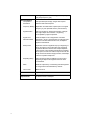
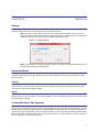
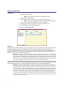
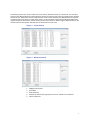
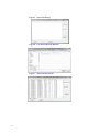
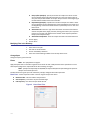
RF Editor Program version 3.0.2.1 ©Copyright 2013 by Bird Electronic Corporation Instruction Book P/N 920-RF-EDITOR Rev. B About This Manual This manual covers the operating and maintenance instructions for the following models: WC-RF-EDITOR Changes to this Manual We have made every effort to ensure this manual is accurate. If you discover any errors, or if you have suggestions for improving this manual, please send your comments to our Solon, Ohio factory. This manual may be periodically updated. When inquiring about updates to this manual refer to the part number and revision on the title page. Definitions Introduction - Describes the features of RF Editor, lists controls and indicators, control tab description, and set up information. Operation - Describes the functionality of RF Editor and how to perform searches, captures, and playbacks. ii iii Table of Contents About This Manual . . . . . . . . . . . . . . . . . . . . . . . . . . . . . . . . . . . . . . . . . . . . . . . . . . . . . . . . . i Changes to this Manual . . . . . . . . . . . . . . . . . . . . . . . . . . . . . . . . . . . . . . . . . . . . . . . . . . . . . . . . . . . . . . i Definitions . . . . . . . . . . . . . . . . . . . . . . . . . . . . . . . . . . . . . . . . . . . . . . . . . . . . . . . . . . . . . . . . . . . . . . . . . i Chapter 1 Introduction. . . . . . . . . . . . . . . . . . . . . . . . . . . . . . . . . . . . . . . . . . . . . . . . . . . . . .1 Main Screen . . . . . . . . . . . . . . . . . . . . . . . . . . . . . . . . . . . . . . . . . . . . . . . . . . . . . . . . . . . . . . . . . . . . . . . 2 Controls . . . . . . . . . . . . . . . . . . . . . . . . . . . . . . . . . . . . . . . . . . . . . . . . . . . . . . . . . . . . . . . . . . . . . . . 2 Specifications . . . . . . . . . . . . . . . . . . . . . . . . . . . . . . . . . . . . . . . . . . . . . . . . . . . . . . . . . . . . . . . . . . . . . . 3 Chapter 2 Operation. . . . . . . . . . . . . . . . . . . . . . . . . . . . . . . . . . . . . . . . . . . . . . . . . . . . . . . . 5 Settings . . . . . . . . . . . . . . . . . . . . . . . . . . . . . . . . . . . . . . . . . . . . . . . . . . . . . . . . . . . . . . . . . . . . . . . . . . 5 Operational Modes . . . . . . . . . . . . . . . . . . . . . . . . . . . . . . . . . . . . . . . . . . . . . . . . . . . . . . . . . . . . . . . . . 5 Tektronix . . . . . . . . . . . . . . . . . . . . . . . . . . . . . . . . . . . . . . . . . . . . . . . . . . . . . . . . . . . . . . . . . . . . . . 5 Agilent . . . . . . . . . . . . . . . . . . . . . . . . . . . . . . . . . . . . . . . . . . . . . . . . . . . . . . . . . . . . . . . . . . . . . . . . 5 Creating Waveform Time Segments . . . . . . . . . . . . . . . . . . . . . . . . . . . . . . . . . . . . . . . . . . . . . . . . . . . 5 Building New Waveforms . . . . . . . . . . . . . . . . . . . . . . . . . . . . . . . . . . . . . . . . . . . . . . . . . . . . . . . . . 6 Build RF File . . . . . . . . . . . . . . . . . . . . . . . . . . . . . . . . . . . . . . . . . . . . . . . . . . . . . . . . . . . . . . . . . . 6 Stitch File . . . . . . . . . . . . . . . . . . . . . . . . . . . . . . . . . . . . . . . . . . . . . . . . . . . . . . . . . . . . . . . . . . . . 6 Editing Files on a Track . . . . . . . . . . . . . . . . . . . . . . . . . . . . . . . . . . . . . . . . . . . . . . . . . . . . . . . . . . . 9 Modifying Files in the Directory . . . . . . . . . . . . . . . . . . . . . . . . . . . . . . . . . . . . . . . . . . . . . . . . . . . 10 Change Span . . . . . . . . . . . . . . . . . . . . . . . . . . . . . . . . . . . . . . . . . . . . . . . . . . . . . . . . . . . . . . . . . 10 Filters . . . . . . . . . . . . . . . . . . . . . . . . . . . . . . . . . . . . . . . . . . . . . . . . . . . . . . . . . . . . . . . . . . . . . . 10 Frequency Shifting . . . . . . . . . . . . . . . . . . . . . . . . . . . . . . . . . . . . . . . . . . . . . . . . . . . . . . . . . . . . 11 Advanced Editing . . . . . . . . . . . . . . . . . . . . . . . . . . . . . . . . . . . . . . . . . . . . . . . . . . . . . . . . . . . . . 11 Modify Groups of Files . . . . . . . . . . . . . . . . . . . . . . . . . . . . . . . . . . . . . . . . . . . . . . . . . . . . . . . . . 12 Edit Header . . . . . . . . . . . . . . . . . . . . . . . . . . . . . . . . . . . . . . . . . . . . . . . . . . . . . . . . . . . . . . . . . . . . . . 12 Integration with Spectro-X . . . . . . . . . . . . . . . . . . . . . . . . . . . . . . . . . . . . . . . . . . . . . . . . . . . . . . . . . . 13 iv Chapter 1 Introduction The RF Editor is a graphical signal editing tool that allows the manipulation of I & Q signal files. Some applications that RF Editor is capable of: Electronic Warfare - Designs robust battlefield or region-specific RF environments for simulation and testing by processing broad segments of spectrum. Wireless Communications - Build new signals for testing and development of satellite and terrestrial, voice, data and telemetry equipment and networks using captured or mathematically generated communication signals. Spectrum Management - Create scenarios to simulate changes in the RF environment by altering the spectrum and testing them in the laboratory. Radar - Use existing libraries of signals to replicate virtually any existing or proposed system for either testing or live use. Note: A self guided demonstration of key RF Editor functions, including sample files, is available for download at: www.xcomsystems.com/resource/Download-Software 1 Main Screen Controls 1 2 9 10 11 3 6 7 12 Item 2 5 4 Description 1 Toolbar 2 Waveform Library 3 Start Time of the time line 4 End Time of the time line 5 Frequency Span (Bandwidth) 6 Editing Track, see “Creating Waveform Time Segments” on page 5. 7 Operational Mode, see “Operational Modes” on page 5. 8 Snap to Grid checkbox 9 Modify File, see “Modifying Files in the Directory” on page 8. 10 Evaluate Search, 11 Send to Spectro-X, see “Spectro-X” on page 11. 12 Edit Header, see “Edit Header” on page 11. 8 Specifications Filtering Modifier Types Pass Band Stop Band (Fs= Sample Rate) Ripple < 0.001 dB (Freq where rejection > 0.001 dB) < Pass Band < (Freq where rejection > 0.001 dB) Rejection > 80 dB (Freq where rejection >80 dB) RF Editor Band Pass Filter Characteristics (Invert for Band Stop) (-a/2) Hz (a/2) Hz -a Hz +a Hz 0 Hz a = Filter percentage * file sample rate (Hz) Band Pass Bandpass 10% (lowpass 5%) Pass Band = ± 0.05 fs, -0.1 Fs ≤Stop Band≥ 0.1 Fs (Band stop has same performance by inverse shape) Bandpass 20% (low pass 10%) Pass Band = ± 0.10 fs, -0.2 Fs ≤Stop Band≥ 0.2 Fs (Band stop has same performance by inverse shape) Band pass 30%, (low pass 15%) Pass Band = ± 0.15 fs, -0.3 Fs ≤Stop Band≥ 0.3 Fs (Band stop has same performance by inverse shape) Band pass 40%, (low pass 20%) Pass Band = ± 0.02 fs, -0.4 Fs ≤Stop Band≥ 0.4 Fs (Band stop has same performance by inverse shape) 3 Filter Parameters Waveform Editing Interpolation/ Decimation 4 Filter Type: (Band Pass, Band Stop), Start Frequency (Hz), Stop Frequency (Hz) User specified span change; integer ratio required between initial and final spans. Frequency Shifting Replication and offset within capture span from original frequency by user specified amount (1Hz resolution). Signal Duration User can lengthen or shorten time duration of sample file; single sample time resolution. Lengthening accomplished by segment repetition. Signal Level Attenuation/Gain Scalar multiplier on I & Q magnitudes. If resultant magnitude > 32,767, all sample files are scaled by fixed amount to maintain relative levels. Then, multiplier is applied to selected file. Ramp In/Out Application of linear magnitude ramp up to beginning of file or ramp down to end of file. Max ramp magnitude equals the difference between max sample amplitude value and zero. User specifies ramp duration in samples. As an option, the user can create a ramp function file, the shape of which is stored as single precision, float sample values at a specific sample rate. Repeating Ramp Same as Ramp In/Out but applied to the end of and beginning of adjacent file segments that have been concatenated. Stitch Builds an output file by concentrating selected segments of a larger file that are delineated by markers. Time Tracks Maximum of 10 File Formats Input & Output: XIQ, TIQ Hardware Requirements Windows 7 PC (64 bit), 10 Mbyte on OS Drive, USB 3.0 or eSATA, mouse or trackpad Chapter 2 Operation Settings Configures the location of the I and Q data file directory that will be utilized. Note: By default, the I and Q files reside in the same directory. With the “Match Q directory to I” box checked, any changes to the I directory will automatically be reflected in the Q directory as well. Uncheck the “Match Q directory to I” if the I and Q files are in different directories or drives. Figure 1 Settings Dialog Note: If there are issues with files not appearing in the list, uncheck the “Show Only Matching Spans” box to see all I/Q file pairs in the selected directory. Operational Modes Operational Mode may be selected. Depending on the span being worked with, one of these operational modes must be selected. Tektronix Works with the spans and sample rates dictated from the digital I/Q outputs from the Tektronix Real-Time Spectrum Analyzer captured with X-COM’s IQC500A. Agilent Allows the user to arbitrarily select the exact span (bandwidth) with corresponding sample rate to match the output from Agilent signal analyzers. Creating Waveform Time Segments Any XIQ file may be used in RF Editor. Those files can be dragged onto any of the 10 time tracks. Waveform segment duration can be extended and, by applying user selected frequency domain functions, RF Editor allows the user to rapidly build complex new spectrum in the time domain and stack carriers in the frequency domain simultaneously. When the segments are aligned as desired on the time tracks, RF Editor can fully combine the waveform segments into a new waveform with a single mouse click. 5 Building New Waveforms Build RF File 1. 2. 3. 4. 5. 6. Set the time scale of the file. Note: “Start Time” and “End Time” at top of window in Figure 2. Select the span to work within. Drag-and-drop a file from the directory onto one of the timeline tracks. Note: A callout will specify where along the track’s timline the file will be set. Edit the file, if needed. See “Editing Files on a Track” on page 9. Repeat Steps 2 and 4 for any other files on any of the 10 time tracks. Go to the Build menu and select Build RF File. Figure 2 Creating Waveforms Stitch File Stitching is a process that concatenates segments of a spectrum capture file which have been selected by the user. It effectively provides a way to cut out undesired portions of a file and reconnect the remaining segments. Segments can be delineated in two ways. The first is via file markers inserted in the file during receipt and processing, by the IQC500A, of TTL level pulses presented to either of its two trigger input BNC connectors. Spectro-X search results can also be used to denote segments. Example - A carrier search is conducted in Spectro-X looking for carriers in a capture file that exceed -40dBm in power and, using search pruning, have a duration not exceeding 50 microseconds (See Spectro-X User Manual and Spectro-X Self Guided Demo manual, both available for free download at www.xcomsystems.com). Spectro-X can export the results of this pruned search to a file that delineates each portion of the capture file in which these user selected criteria have been met and in a manner usable by RF Editor. RF Editor can utilize either type of segment designation; search results or markers in the Stitch Function. If RF Editor stitches using markers then, the new file will contain the segments delineated by the markers and the segments will be concatenated with no blank time between them. A stitched file using search results will result in something slightly different. Example - A capture file of 100 μs in length is searched for carriers with the criteria of power levels above -15dBm. Further, assume there are three time segments in which carriers meet this threshold. The first segment occurs in the file from time 1 μs to 5 μs. The second segment occurs during the file time from 10 μs to 12 μs and the third from 15 μs to 25 μs. If these search results are brought in to the RF Editor Stitch Function and the first and third search results are checked as the ones to be stitched, then the resulting file will be 25μs long. The first microsecond of the file will contain zeros (no spectrum). File time 1μs to 5 μs will contain whatever was in the searched file during that time period. There will be zeros from file time 5μs sample to 15 μs and it will contain whatever was in the searched file from time 15μs to 25 μs. 6 The Stitching function can use the results from Carrier Search, Waveform Search, or Pulse Search. The time value entered in the Offset field will be used to adjust the Start for each search result. Entering a negative value will back the start in time. While Carrier Search and Pulse Search results contain durations, the Waveform Search results do not. When using Carrier Search or Pulse Search results, the time entered in the Duration field will be added (use a negative number to decrease the amount of time) to each result’s duration. When using the Waveform Search, the amount entered in the Duration field will serve as the duration for each result. Figure 3 W f S h Figure 4 1. 2. 3. 4. 5. Carrier Search Waveform Search Highlight a desired file. Go to Build. Select Stitch File. Deselect the markers (file segments) that are not wanted in the worksheet. Click on Create File. 7 8 Figure 5 Stitch File Dialog Figure 6 Use Search Results Window Figure 7 Stitch File Worksheet Figure 8 Stitch File Spectrogram Editing Files on a Track 1. 2. 3. Drag a file from the file list onto a time track. Right click on the file. Modify any of the following parameters: Delete - Removes the file from the track. Start in File - Start point of a sample in seconds. End in File - End point of a sample in seconds. Note: These allow the user to specify the portion of the file that will be used or will be the target of the selected functions. Track - Sets the track that the file will be located in. Note: Any drag overlay will result in a width change. Start on Track - Sets the Start Time on the track. End on Track - Sets the End Time on the track. Note: Start and End Times will correlate to each other unless the Maintain Width checkbox is unchecked. Note: In the case of unchecking the Maintain Width box, the file segment specify by the Start in File and End in File will either be shortened or lengthened (by repeating) by the difference of End of Time minus Start on Track. Attenuation/Gain - Adjusts the amplitude of the file. Note: Enter a positive number less than 1 as this process is a multiplication operation of the I & Q waveforms and results in a voltage gain, not a power gain. Example - An attenuation factor of 0.0001 results in a 80dB shift in amplitude (20logX). Note: Doubling the modifier will raise the amplitude by a factor of 6 dB per occurrence. Reducing the modifier by 2 will lower the amplitude by 6 dB per occurrence. 9 4. 5. Ramp In/Out (Samples) - Specify the number of samples over which a linear ramp is applied. Ramp magnitude transitions from 0 to max sample value linearly over the specified number of samples. Ramp increases at the beginning of the selected file and decreases at the of the file. Repeat Ramp (Samples) - Specifies the number of samples over which a linear ramp is applied to the end and beginning of concatenated files that result from the lengthening of the time duration of a file as specified by Start on Time and End on Time. Attenuation File - Browse or type in the file location and name of the file that contains sampled values (single precision, floating point values) of a ramp function that is not linear to be applied to the number of file samples specified in Ramp In/Out or Repeat Ramp. Attenuation Sample Rate - Enter the sample rate used in the Attenuation File. Click on Apply. Click on Done. Modifying Files in the Directory 1. 2. 3. 4. Select the correct span. Left-click on the desired file. Click on the Modify File button. Select one of the following modifiers from the drop down menu: Change Span Changes frequency span of the file. Filters Note: See “Specifications” on page 3. Apply band pass filters to waveform segments from the file list with a 3dB pass band that is specified as a menu selected percentage of the capture BW of the file containing the signal. Note: If the file was captured by the IQC500A, the capture BW equals the span setting of the spectrum analyzer used as the RF front end. RF Editor allows the signal span to be reduced by a simple, dialog box decimation operation. Band Pass - Passes frequencies within a certain range and rejects the others. 10 Band Pass Filter - Sets the width of the pass band. Start Frequency - Sets where the pass band will begin. End Frequency - Sets where the pass band will end. Figure 9 Band Pass Filter Band Stop - Passes frequencies except those in a certain range. Band Stop Filter - Sets the size of the stop band. Start Frequency - Sets where the stop band will begin. End Frequency - Sets where the stop band will end. Frequency Shifting Spectrum can be replicated and offset from the original by a user specified amount of frequency within the span of the signal file. Figure 10 Frequency Shifting Advanced Editing RF Editor also meets the need for higher precision editing and saves time through its Advanced Modify window. Multiple simultaneous operations can be performed, the new file saved and immediately available for addition to an RF Editor waveform time track. Input - Sets the read directories for the I data. Output - Sets the write directories for the Q data. Modifications - Individual modifiers that can be separately adjusted. Frequency Shift By - Shifts the waveform by x Hz within the span. Decimate By - Removes sample from waveform. Interpolate By - Replicates samples in the waveform. Filter - Specifies the filter percentage as a function of the file sample rate. Interpolate By - Replicates samples in the waveform. Decimate By - Removes samples from the waveform. Frequency Shift By - Shifts the waveform by x Hz. 11 Figure 11 Advanced Editing Modify Groups of Files Allows for the simultaneous modification of multiple files within a chosen directory. See “Modifying Files in the Directory” on page 10. Figure 12 Modify Groups Dialog Edit Header Span - Changes the Frequency Span. Center Frequency -Changes the Center Frequency Scale Factor - Sets the scale factor. RBW - Sets the Resolution Bandwidth. Protect - 0 marks that it is not write protected, 1 marks that it is write protected. Markers - Lists all the markers in the file. 12 Figure 13 Edit Header Integration with Spectro-X RF Editor is integrated with Spectro-X. This allows the user to highlight any waveform in the RF Editor Waveform directory list and, with a single mouse click, have that entire file, or a portion of it, immediately available for viewing and performing carrier and waveform searches in Spectro-X. Refer to the Spectro-X manual. 13 14