1
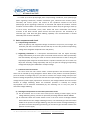
SBW(F)·DBW series Voltage Stabilizer for Industry Use
User Manual
1. Summary
DBW/SBW(F) compensation Automatic Voltage Stabilizer is designed referring to
international congener products. When input voltage fluctuated, it can output the voltage
automatically and stably. Our product has many advantages as follows: high power capacity,
high efficiency, wide input voltage range, high output voltage precision, smooth voltage
regulation, broad load application, long continuous work life, no wave distortion, strong
protection performance, little dimension, light weight, work reliability, easy operation, simple
maintenance and so on.
This product is widely used in industrial and mining enterprise, communications, broadcast
television, traffic, national defense, construction, medical treatment, large-scale mechanical
and electrical equipment of scientific research and culture departments, production
assembly line, construction project equipment, broadcast television equipment, medical
equipment, precision machine tool, electronic computer, precision instrument, elevator and
so on.
2. Model & Technical Specification
a) The model of SBW series voltage stabilizer is shown as below:
X BW —— XXX
F: Independent phase regulation
Rated Capacity(KVA)
Compensation voltage stabilizer
D:Mono-phase、S:Three-phase
b) Main Technical Specification
Input voltage
Output voltage
Output voltage
wave
220V/380V +/-20% or 30%;
custom design available
220V/380V ±(2~5)%, can be set
Efficiency
Insulation
resistance
Withstand
Sine wave
voltage
Waveform
Distortion
No additional waveform
distortion
Over-load
capacity
Response speed
≤1.5S (when outside voltage has 10% of change)
≥ 98%
>2MΩ
2000V/1min
1min. at 2 times of the
rated current.
NeoPack International Limited Add.: XIXING ROAD, LIUSHI, WENZHOU, ZHEJIANG, P.R.CHINA 325604
Tel.: +86-577-2787-6782 Fax: +86-577-2787-6752
E-mail: sales@neopower.hk
Http://www.neopower.hk
c) Main Protection Function
Over-voltage &
under-voltage
Protection
When output voltage exceeds ±10% rated voltage, Stabilizer cut off output source
automatically.
Phase sequence
protection
When the sequence of three phase are incorrect, Stabilizer cut off output
automatically
Phase
protection
If phase lacked, Stabilizer cut off output automatically
lack
Mechanical
breakdown
protection
If servomotor or drive system happened to malfunction, Stabilizer cut off output
automatically
Short-circuit
protection
If output short circuit, air switch cut off input automatically
Bypass Function
When the breakdown happens to the stabilizer, the bypass will work
manually(default) or automatically(can be customized by requirement)
d) Models and Specification
Phase No.
Single-phase
Model
(KVA)
Rated
capability
(KVA)
Output
max
current
(A)
Size (mm)
D×W×H
Cabinet
QTY
Weight
DBW-10
10
45
500×650×1320
One
180
DBW-15
15
68
500×650×1320
258
DBW-20
20
91
500×650×1320
290
DBW-25
25
114
500×650×1320
310
DBW-30
30
136
500×650×1320
320
DBW-40
40
182
500×700×1500
338
DBW-50
50
227
620×800×1500
354
DBW-60
60
273
620×800×1500
390
DBW-80
80
364
680×920×1620
410
DBW-100
100
455
680×920×1620
470
DBW-120
120
545
680×920×1620
498
DBW-150
150
682
680×920×1750
531
DBW-180
180
818
680×920×1750
540
DBW-200
200
909
680×920×1750
550
NeoPack International Limited Add.: XIXING ROAD, LIUSHI, WENZHOU, ZHEJIANG, P.R.CHINA 325604
Tel.: +86-577-2787-6782 Fax: +86-577-2787-6752
E-mail: sales@neopower.hk
Http://www.neopower.hk
(kg)
Three-phase
SBW-20
20
30
720×600×1250
One
SBW-30
30
45
720×600×1250
240
SBW(F)-50
50
76
720×600×1250
287
SBW(F)-60
60
91
720×600×1250
301
SBW(F)-80
80
121
820×620×1440
379
SBW(F)-100
100
152
820×620×1440
414
SBW(F)-120
120
182
820×620×1440
435
SBW(F)-150
150
227
770×900×1620
577
SBW(F)-180
180
273
770×900×1620
600
SBW(F)-200
200
303
770×900×1620
610
SBW(F)-225
225
341
800×1000×1650
705
SBW(F)-250
250
379
800×1000×1650
728
SBW(F)-300
300
455
900×1100×1850
890
SBW(F)-320
320
485
900×1100×1850
815
SBW(F)-350
350
530
900×1100×1850
940
SBW(F)-400
400
606
900×1100×1850
1020
SBW(F)-450
450
681
900×1100×1850
1063
SBW(F)-500
500
758
1050×900×1860
SBW(F)-600
600
909
1050×900×1860
SBW(F)-800
800
1212
1000×800×1860
SBW(F)-1000
1000
1515
1000×800×1860
SBW(F)-1200
1200
1818
900×900×1860
SBW(F)-1400
1400
2121
1000×1100×1860
3200
SBW(F)-1600
1600
2424
1000×1100×1860
3800
SBW(F)-1800
1800
2727
1000×1200×1860
4800
SBW(F)-2000
2000
3030
1000×1200×1860
4990
SBW(F)-2500
2500
3798
1250×1200×2000
6600
SBW(F)-3000
3000
4545
1250×1200×2000
7200
Two
230
1350
1390
three
2180
2370
Four
2670
3. Working Condition
The SBW(F) and DBW series voltage stabilizers should be used indoor, if require outdoor use,
please ask us if it is available. The normal service conditions are as follow:
1) Ambient temperature: -5℃~+45℃;
2) Height above sea level: not exceeding 1000 meters;
3) Relative temperature: ≤90%;
4) There should be no gas, vapor, chemical sediments, dust, dirt, or other volatile and
erosive medium that will influence the insulation intensity of the voltage stabilizer at the
installation site;
5) There should be no serer vibration or bump at the installation site;
6) The user should consult with us if the product is used in special using condition which
does not meet the above mentioned conditions.
NeoPack International Limited Add.: XIXING ROAD, LIUSHI, WENZHOU, ZHEJIANG, P.R.CHINA 325604
Tel.: +86-577-2787-6782 Fax: +86-577-2787-6752
E-mail: sales@neopower.hk
Http://www.neopower.hk
4. Structure
It is made up of three phase/single phase compensating transformer, three phase/single
phase regulating transformer, isolation transformer, gear, electrical brush contact system,
case-body and control system. The surface of the cylindrical solenoid of the three
phase/single phase regulating transformer is burnished and wiped off insulation. Smooth
conductor surface enables it to contact with the electrical brush well; the gearing is made up
of servo motor, worm-wheel, worm, chain wheel and chain. Reasonable and reliable
structure of the brush contact system assures the brush pressure. The case-body is of
enclosed type, small bulk and good radiating capability. The instrumentation is located
observably with accurate indications.
5. Basic components and circuit
1) Compensating transformer
When the polarity and magnitude voltage increased on the primary coil changes, the
secondary coil that is connected with the load loop in series will produce compensating
voltage with changeable amplitude value and polarity.
2) Regulating transformer is a three-phase autotransformer that can adjust secondary
voltage automatically. It has three pairs of electrical brushes that can slide symmetrically
and automatically. By using the chain to drive the electrical brush to slide on along the
exposed part(slide way)of the autotransformer’s cylindrical solenoid, the servo motor can
adjust the secondary voltage reposefully and carry the point of changing compensating
voltage and keeping the stabilization of output voltage.
3) Control circuit of servo motor
The servo motor has two control modes: manual-operation and automatic-operation,
which can be selected by using changeover switch. When at the position of manual-operation,
press the button of voltage step-up is you want to increase the output voltage and press the
button of voltage step-down if you want to decrease the output voltage so as to make the output
voltage meet the power supply requirement. At this time, the voltage stabilizer does not have the
function of voltage stabilizing. When the automatic operation is selected, the voltage
step-up/down can be detected automatically by the detecting unit to carry the point of
automatic voltage stabilizing.
4) Switchgear and operation circuit of three phase main circuit
(1) The AC contactor are set in the main circuit (one for shifting of mains supply, one for
voltage stabilizing startup, and one for protection)of voltage stabilizer 30KVA-100KAV.
(2) An automatic switch and a knife switch are set in the main circuit of voltage stabilizer
above 150K.To turn the voltage stabilizing function, one should only put the knife switch
handle to the position of voltage stabilizing, and press the button of voltage stabilizing. If
you want to connect the power grid directly, you should only put the knife switch to the
position of mains supply.
NeoPack International Limited Add.: XIXING ROAD, LIUSHI, WENZHOU, ZHEJIANG, P.R.CHINA 325604
Tel.: +86-577-2787-6782 Fax: +86-577-2787-6752
E-mail: sales@neopower.hk
Http://www.neopower.hk
5) Detecting and adjusting unit of three-phase voltage stabilizer
Sampling control transformer takes out the sampling voltage and control voltage from
the output terminal of the voltage stabilizer. The upper-limit reference voltage can be
gotten after transforming, commutating, wave-filtering, stabilizing, and dividing of
control voltage. The signal voltage, which changes subject to output voltage, can be
gotten after transforming, commutating and wave-filtering of sampling voltage. If output
it to the comparator for comparison, when the signal-voltage is between the upper-limit
and lower-limit voltage, all the contacts of the control relays are on“OFF”position, when
the signal voltage exceeds the upper-limit and the upper-limit reference
voltage(precision),the control relay and contact relay will actuate. Servo motor runs to
adjust compensating voltage and stabilize the output voltage. In a word, when the
changing of output voltage exceeds the permitted-range of set-precision, the voltage
detecting unit will of send the command of adjusting the output until the voltage
resumes to the permitted-range of the set precision. The voltage stabilizing precision can
be adjusted between ±1% and 5%with the potentiometer Pr3. The central position of the
rated voltage is adjusted by the regulator potentiometer.
6) Three-phase protection circuit
1) The automatic switch QA protects the main circuit from overload and short out. The
QLS1 and QLS2 limit switches from the overrun protection circuit. When the
electrical brush slides and touches the upper-limit or lower-limit switch, coil of the
voltage regulating relay will be disconnected with the power supply to release the
relay and stop the servo motor and protect the circuit from overrunning.
2) The normally closed contact of the control relay is closed while the over and under
voltage protection circuit is in normal running state. When the signal voltage exceeds
over voltage protection set-value or fall under the under pressure protection set
value, the normally closed contact of the protection relay will be cut off and
accordingly the control circuit will be cut off, the automatic compensating system
will quit working. The over voltage set value is about 420V and the under voltage set
value 320V and acoustic optic alarm is set well before delivery.
3) Protection circuit for phase sequence and loss of phase
When the leading phase sequence of the three phase power supply is mismatched
or lose phase. The indicator light of the phase sequence protector will be off, and
whole machine will be in automatic protection state.
7) This machine has two control boards named A and B. if there is any malfunction found on
control board A during using, you can prod the changeover switch of the standby board
to control board B, which will work instead of board A.
8) Voltage detecting and adjusting unit of single phase voltage stabilizer
The operation principle of the detection and adjusting unit of the single phase voltage
NeoPack International Limited Add.: XIXING ROAD, LIUSHI, WENZHOU, ZHEJIANG, P.R.CHINA 325604
Tel.: +86-577-2787-6782 Fax: +86-577-2787-6752
E-mail: sales@neopower.hk
Http://www.neopower.hk
stabilizer is the same as the three phase voltage stabilizer.
The automatic switch QA protects the main circuit from over voltage and short out. The
automatic voltage compensating system is set with overrun protection. When the
electrical brush slides to each side and hit the limit switch, the normally closed contact
will be cut off, and servo motor will stop.
When the over voltage protection circuit is in normal running state, the normally closed
contact of the control relay is closed. When the signal voltage exceeds the set value of
over voltage protection, the normally closed contact of the control relay will be cut off
and accordingly the control circuit will be cut off, and the automatic compensating
system will quit working.
6. Service condition
The SBW(F) and DBW series voltage stabilizers should be used indoor. The normal service
condition are as follow:
7) Ambient temperature: -5℃~+45℃;
8) Height above sea level: not exceeding 1000 meters;
9) Relative temperature: ≤90%;
10) There should be no gas, vapor, chemical seciment, dust, dirt, or other volatile and erosive
medium that will influence the insulation intensity of the voltage stabilizer at the
installation site;
11) There should be no serer vibration or bump at the installation site;
12) The user should consult with us if the product is used in special using condition which
does not meet the above mentioned conditions.
7. Notice for ordering
1) To place an order, you should make clear the model of the product, the capacitance,
rated output voltage, range of input voltage variation, precision of voltage stabilizing and
power supply input position.
2) For special requirements, please contact with our technical department for further
advices.
NeoPack International Limited Add.: XIXING ROAD, LIUSHI, WENZHOU, ZHEJIANG, P.R.CHINA 325604
Tel.: +86-577-2787-6782 Fax: +86-577-2787-6752
E-mail: sales@neopower.hk
Http://www.neopower.hk
Manual for debugging and maintenance
1. Unpacking examination
(1) Whether the pack is damaged during transportation.
(2) Whether the technical document, and fittings are all complete.
(3) Whether the compensating transformer, the regulating transformer and other
components are in good condition.
(4) Whether the fasteners are loosened, shifted, and whether the terminals are well
connected.
(5) Whether voltage regulating system and gearing are safe and reliable. If the carbon brush
is misplaced or broken, correct it or replace it in time.
Notice: Do not put the machine in a damp place for a long time; otherwise, the
machine’s performance and quality will be influenced.
2. Notice for location
(1) The installation site of the voltage stabilizer should be dry and ventilated without severe
vibration, dust or sand, and rainfall penetration.
(2) During removal, it should be handled with care, over-incline is banned. The stress on
chassis should be even. The machine should be placed on even keel.
(3) There should be enough space around the machine to insure the ventilation and the
convenience for maintenance.
3. Insulation Requirements
Strap the input and output terminals and lead out the testing point. Test the insulation to
ground of the testing point with a 1000V megohm meter, the measured value should be
more than 1MΩ, if the value is less than 1 MΩ, check the causes, or dry the humidity in the
case with an electric heater until it reaches the standard value.
4. Insulation and connection
(1)Leading connection for the voltage stabilizer under 225KVA; The three-phase wires A, B
and C of the input power supply should be led in from the lower and rear part of the case,
through the current transformer, (the number of turns is according to the request of the
nameplate) and connected with the upper pile head of the air switch in the case.
(2)Leading connection for the voltage stabilizer above 320KVA: The three-phase wires A, B
and C of the input power supply should be connected with the copper bus corresponding to
the upper pile head of the air switch or the air breaker (the bus is marked with the letters A,
B and C).
(3)Connecting wire for multi-case products: the connecting wire for the double-case and
four-case can be the soft copper wire with section no less than 1mm² and the wire should be
connected with the line contact bank of the inter-case terminal and ranged up-to-down
correspondingly.
(4)Connection of outgoing line: Each connection terminal marked with”output voltage” on
the voltage stabilizer should be connected with load. The specification of the connection wire
is decided by the user according to the load. Generally, it should be the same as the leading
wire.
NeoPack International Limited Add.: XIXING ROAD, LIUSHI, WENZHOU, ZHEJIANG, P.R.CHINA 325604
Tel.: +86-577-2787-6782 Fax: +86-577-2787-6752
E-mail: sales@neopower.hk
Http://www.neopower.hk
(5)Chassis protective earthing: the gauge of the earth wire is carried out according to the
relative stipulations of local power supply authority. The earth wire should be connected
with the pile head, which marked with “earth wire” in the case. The resistance of earth wire
should be less than 0.4Ω.
(6)The gauge of the power leading wire can be chosen by the user according to the magnitude of
machine’s capability. The following table is only for reference.
Capacitance
(KVA)
20
30
50
100
180
225
320
400
Wire(mm²)
6
10
16
50
90
150
240
Copper bus wiring is suggested.
500
600
800
1000
5. Earthing examination
The first and most important step for the debugging personnel is to check the connecting
wires carefully, which is pivotal to assure the reliable running of the voltage stabilizer. The
detailed working contents are as follows:
(1) Check the main loop connection wire and see whether it is firm and reliable, whether the
connecting wires of the universal breaker switch of QN knife switch comes loose. Screw it
down if it comes loose.
(2) Check the contact wires of all kinds of electrical devices behind the panel such as
voltmeter, ammeter, lamp indicator button, change-over switch and see whether they are
firm and reliable. You should screw them down if they come loose.
(3) Check the circuit board and see whether connecting wire of each point comes loose. You
should screw it down if it comes loose.
Check the servo motor on the voltage regulator and see whether the connection wire of
limit switch is reliable. You should screw it down if it comes loose.
(4) Check the control circuit board and circuit breaker which control the power supply of
electric motor in the control board and see whether they are closed.
6. Operation of electrifying and debugging
(1) Put the”Manual/Automatic” optional switch to the position of “Manual”.
(2) Put the knife switch to the position of “Voltage Stabilizing” the voltage stabilizer is in
zero load state, switch on the power supply, close the switch QA, at this time, the
indicator light of the three-phase electrical source on the panel is on. The reading is
shown on the input voltmeter, and the input power-on test is finished.
(3) Press the button of “Voltage Stabilizing”, about 5-15 seconds later, the delay relay is
closed, which makes the output contactor electrified and close. The green light for
Voltage Stabilizing is on. Then, according to the reading shown on the output voltmeter,
press button of Voltage Step-up or Voltage Step-down, the pointer of output voltmeter
will rise or fall accordingly and the manual voltage regulation test is finished.
Notices:
If the voltage stabilizer cannot be started up and the indicator light of the phase
sequence protector does not shine after pressing the button of “Voltage Stabilizing”, the
means the phase sequence is wrongly connected. To clear the trouble, you should first cut off
the power supply and then only exchange any two leading wires of the three.
After pressing the button of “Voltage Stabilizing”, the voltage stabilizing will have output
NeoPack International Limited Add.: XIXING ROAD, LIUSHI, WENZHOU, ZHEJIANG, P.R.CHINA 325604
Tel.: +86-577-2787-6782 Fax: +86-577-2787-6752
E-mail: sales@neopower.hk
Http://www.neopower.hk
voltage, but instantaneous warning and automatic trip protection will function, which is to
show the connection is right. As the input voltage is on the high side, and the output voltage
is also in high side and will exceed the protection-value for over voltage. At this time, you
should put the “Manual/Automatic” optional switch to the position of “Automatic”, push the
button of “Voltage Stabilizing”, watch the reading on the voltmeter until the voltage is
stabilized to 380V, and then operate as step 4. Under the two states of “Voltage Step-up” and
“Voltage Step-down” debug the stabilizer and make clear if it can stabilize the voltage to
380V automatically. If anything abnormal occurs, please contact with our company at once.
(4) Put the button of “Manual/Automatic” switch to position of “Manual”, push the button
of “Voltage Step-up” and make the voltage value reach to 400V or so. Shift the switch to
the position of “Automatic”, the output voltage will accordingly fall to 380V or so. This is
voltage step-up test. Put the button of “Manual/Automatic” switch to the position
of ”Manual”, push the button of “Voltage Step-down” and make the voltage value reach
to 360V or so. Shift the switch to the position of “Automatic”, the output voltage will
according rise to 380V or so. This is voltage step-down test. Automatic voltage stabilizing
test is finished upon the success of above two tests.
Put the “Manual/Automatic” switch to the position of “Automatic” when the debugging
is over and the voltage stabilizer will be in running state.
(5) Put the knife switch to the position of “mains supply”, close the QA switch and you can
get the “mains supply” output.
Notice for debugging voltage stabilizers above 400KVA;
The capacitance products of this kind have the similar debugging method with the
voltage stabilizer under 400KVA,But as the capacitance is relatively large, generally the
equipment of automatic power up and time delay input are not designed(which can be
added according to the user’s request)
Notice for debugging of split-phase voltage regulating stabilizer:
The capacitance products of this kind have the similar debugging method to the
above-mentioned stabilizer. The difference is that the split phases regulate the voltage severally;
the regulating system of each phase is separate and uncorrelated with other phase. Each phase is
set with manual/automatic switch; the debugging should be carried phase by phase.
7. Load operation
When debugging, the load should be added in step by step, one should take strict
precautions against overload.
It is strongly recommended that the load of voltage stabilizer should not surpass80% of
rated value, the stabilizing efficiency and the reliability is the highest at this time. If the load
is assuredly on the high side, you should strengthen the cooling measures when use it.
If breakdown occurs at the time the machine is running with large load, it is required that
the load should be increased step by step when the power supply is resumed. One should
take strict precautions against simultaneous start up of several high-power electro motors, or
the overwhelming electric current will damage the voltage stabilizer.
NeoPack International Limited Add.: XIXING ROAD, LIUSHI, WENZHOU, ZHEJIANG, P.R.CHINA 325604
Tel.: +86-577-2787-6782 Fax: +86-577-2787-6752
E-mail: sales@neopower.hk
Http://www.neopower.hk
Common Malfunction and Troubleshooting
No.
Malfunction
Cause
Solution
1
Can not start
1.Error phase sequence of
input power wiring or
abnormal electric network;
1. Change any two power supply
wires, or check if the power line is
in order(it is in correct phase order
if the phase order protector light is
on. And then start the device
2.Air switch in the device is
not closed or broken;
2. Switch on or replace air switch;
1.Samling
broken;
1,2,3 and 4: repair or replace
2
Can
not
regulate
the voltage
transformer
is
2.Control circuit board is
broken;
3.The motor is broken
4.The mechanical
failure
system
5.Load feeds back higher
harmonic wave
3
Voltage
regulation
actuates in one
direction only
1.Normally closed contact of
travel limit switch is open or
broken;
Replace
2.Manual/Automatic
changeover switch contact is
broken;
3.Step-up/down relay on the
control panel is broken;
4
No
output
voltage
1.normally closed contact of
stop button is open;
Replace
2.The contact of voltage
stabilizing button is broken;
3.Contact KM in main loop is
broken
5
Often trip
1.Over voltage value of
control circuit board is not
adjusted well;
Have it adjusted or repaired by
professional personnel.
2. The resistance of control
circuit board varies.
8. Function, collocation, and adjusting method of the components on control panel:
For loss of phase and phase sequence reply: When meet with leading misphase or loss of
NeoPack International Limited Add.: XIXING ROAD, LIUSHI, WENZHOU, ZHEJIANG, P.R.CHINA 325604
Tel.: +86-577-2787-6782 Fax: +86-577-2787-6752
E-mail: sales@neopower.hk
Http://www.neopower.hk
phase, the indicator light does not shine and the machine cannot start.
For over voltage and under voltage protection reply: When the voltage stabilizer goes
wrong or the leading voltage is too high or too low and makes the output voltage exceed 420V or
less than 320V, KC3 actuates (protection light is on) to stop the voltage stabilizer, and the siren
will sound. Use PR3 relay to adjust the value of over voltage protection point. Use PR1 to adjust
the value of under voltage protection point.
For KC1 step-up relay: When the output voltage of the stabilizer is under the set
stabilizing range.KC1 actuates to make the servo motor drive the electrical brush and increase the
output voltage to 380V, and KC1 release. The process of automatic regulating is over.
For KC2 step-down reply: When the output voltage of the stabilizer exceeds the set
stabilizing range, KC2 actuates to make the servo motor drive the electrical brush and lower the
output voltage to 380V,and KC1 release. The process of automatic regulating is over.
For RP1 central voltage regulating relay: Put the voltage stabilizer in zero load running
state, fist adjust RP2 to minimum (adjust anti-clockwise), then revolve RPP1; Revolve
anti-clockwise, to lower the output voltage and revolve clockwise to raise the output voltage.
For PR2 regulating relay of voltage-stabilizing precision: Revolve the potentiometer
anti-clockwise, the voltage stabilizing precision inclines to direction of 1%; revolve the
potentiometer clockwise, the voltage stabilizing precision inclines to the direction of 5%.
9 . Daily maintenance
During operation, scout regularly the working state of the voltage stabilizer, check the
temperature rise of the compensating transformer and regulating transformer and see if they are
normal, if the load surpasses the rated value, if the input voltage surpasses the stipulated limit, if
the regulating system and gearing (includes gearing changes and reduction case) are working
normally, if carbon brush racks come loose, If the carbon brushes are on the same planar and the
same line. None of the problems mentioned above is permitted. So you should solve it in time if
any of the problems is found. For further information, please notice the management personnel
for solution to avoid damaging the equipment.
It is suggested that maintenance should be made every three months, which includes:
(1) Clear up the dust and dirt on the components of the voltage stabilizer.
(2) Check the components and replace them if they are broken.
(3) Check the decelerator of regulating system and the chain gearing and see if they are
working normally. You should keep the chains lubricant, and correct the tension of the
chains; replace the broken or greatly abrased brush strips. Clean the coil of the columnar
regulator with carbon tetrachloride and cotton.
(4) Make records of maintenance carefully.
NeoPack International Limited Add.: XIXING ROAD, LIUSHI, WENZHOU, ZHEJIANG, P.R.CHINA 325604
Tel.: +86-577-2787-6782 Fax: +86-577-2787-6752
E-mail: sales@neopower.hk
Http://www.neopower.hk