1
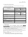
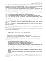
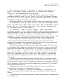
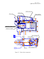
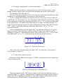
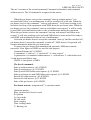
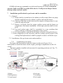
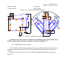
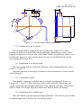
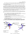
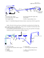
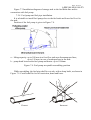
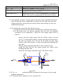
MANUFACTURER:
ADVERS Limited Liability Company
Sales department
11 Lesnaya str. Samara 443100
Russia
Tel.(846) 270-68-64
Fax (846) 270-65-09
E-mail: advers - ts @ yandex.ru
Warranty support department
Tel. (fax): (846) 266-25-41,266-25-43
Tel. (846) 266-25-42, 266-25-39
Е -mail: garant@autoterm.ru
E-mail: advers-garant@yandex.ru
Technical support:
Е -mail: support@autoterm.ru
Tel. (846) 263-07-97 extension.231
Binar 5B, Binar 5B-С, Binar 5D, Binar 5D-С
engine pre-heater
for vehicles with liquid cooling system
User Manual
АДВР.048.00.00.000 РЭ
Page 2 of 34
АДВР.048.00.00.000 РЭ
Table of Contents
1.
2.
3.
4.
5.
7.
8.
9.
10.
11.
12.
13.
14.
Introduction. ......................................................................................................... 3
Technical data and characteristics. .................................................................... 4
Safety measures. ................................................................................................... 4
Description of pre-heater set-up and operation. ............................................... 5
Pre-heater control unit....................................................................................... 6.
The pre-heater Control devices (according to the choice of the consumer). 11
Installation specification for pre-heater and its assemblies. .......................... 21
Post-installation checkout.................................................................................. 27
Recommendations. ............................................................................................. 28
Transportation and storage. .......................................................................... 30
Warranty.......................................................................................................... 30
Pre-heater delivery configuration ................................................................. 30
Packing and acceptance certificate. .............................................................. 31
Sale and installation certificate...................................................................... 31
Page 3 of 34
АДВР.048.00.00.000 РЭ
1. Introduction
The present User Manual gives information on set-up, operation and servicing
of Binar 5 and Binar 5D starting pre-heaters and their modifications (hereinafter
referred to as– pre-heater), which are used for start heating and warming – up
of vehicles with liquid cooling system and engine displacement up to 3.5l at ambient
temperature as low as minus 45°С. Fuel used for Binar 5B starting pre-heater
operation is petrol, for Binar 5D- diesel fuel is used. Binar 5B-С and Binar 5D-С
have the lead for connection with vehicle alarm system or for GSM- modem
mounting.
The pre-heater functions are following:
1. Fail-safe starting engine operation under low ambient temperature conditions.
2. Additional heating of engine and passenger compartment with the engine
running under hard frost conditions.
3. Heating of passenger compartment and windshield at low subzero temperatures
(to remove icing) with the engine inactive.
These functions are supported by the pre-heater basic hardware. Its modular
structure makes it feasible to connect with devices supporting the other functions,
thus improving functionality of the basic hardware purchased and installed initially.
It is possible to operate by the heater with control panel with timer (hereinafter
referred to as– control panel) installed on the car dashboard. It is possible to operate
by the pre-heater Binar 5B-С and Binar 5D-С by the control panel or remotely with
the help of GSM-modem by SMS sent by mobile phone. If there’s alarm signaling
system installed in the car one can use its free channel to operate by the pre-heater.
The pre-heater’s activation time is possible to be programmed by control panel.
While operating the control panel indicates the temperature of the cooling system and
operation mode of the pre-heater. In case of failure the code of malfunction is
indicated.
Minor changes performed on the heater structure by the Manufacturer may not be
documented in this Operation Manual.
Page 4 of 34
АДВР.048.00.00.000 РЭ
2. Technical data and characteristics.
Performance specifications are given with ±10% tolerance at 20°С ambient
temperature and 12V nominal voltage.
Characteristic
model
Binar 5 D
Binar 5D-C
Binar 5B
Binar 5 B-C
Heat productivity, kW
5±0.5
Nominal supply voltage, V
12
Acceptable deviation, V
9.5…16
Fuel
petrol
meeting
requirements
of
GOST 51105
Fuel consumption, l / h
0.7
Power consumption with the pump, max, 80
W
Power consumption on start mode (100 100
sec),W
Maximum liquid heating temperature, Cº +85
Cabin heater fan switching at liquid +40
temperature
Start mode
Manual or automatic
Time of one working cycle, min
40
Pre-heater mass in full configuration, kg, 8
max
Diesel
meeting
requirements
of
GOST 305
0.6
3. Safety measures.
3.1. The pre-heater
and its components
shall be installed only by
authorized companies by reason of it complicated structure: there’s a combustion
chamber where fuel burns, a heat exchanger which provides heat transfer to the
cooling liquid, fuel pump, air pump, control unit, which control and operate the work
of the heater according to the program, heat sensors, etc.
3.2. While installation or dismantling the pre-heater, safety measures specified for
activities with car wiring harness and fuel supply line must be observed.
3.3. The pre-heater shall be used only for purposes described in the present User
Manual.
3.4. It is prohibited to lay the fuel pipe inside the passenger
compartment or driver’s cab.
3.5. It is prohibited to use the pre-heater in case of leaky fuel system.
3.6. Vehicle with the pre-heater shall be equipped with a fire extinguisher.
Page 5 of 34
АДВР.048.00.00.000 РЭ
3.7. To avoid possibility of poisoning with the toxic exhaust gas generated by the
operating pre-heater, the exhaust pipe shall be set in a manner preventing discharge
gas ingress into the driver’s cab or its intake by the heat exchanger fan.
3.8. To avoid possibility of poisoning with the toxic exhaust gas generated by the
operating pre-heater, it is prohibited to use the pre-heater in enclosed car parks
having no ventilation (garage, workshop and etc.)
3.9. It is prohibited to use the pre-heater in areas, where highly
inflammable vapors or ample quantity of dust may be generated or accumulated.
3.10. While fueling the truck the pre-heater shall be switched off .
3.11. It is prohibited to se battery master switch in the pre-heater electric circuit.
3.12. The pre-heater shall be disconnected from the accumulator battery when
welding is performed with the vehicle.
3.13. It is prohibited to connect the pre-heater to the electric circuit of the vehicle
with the engine running and accumulator battery missing.
3.14. It is prohibited to switch off pre-heater power before ending of the purging
cycle.
3.15. It is prohibited to connect and disconnect the pre-heater plug when the preheater power is on.
3.16. It is recommended to restart the pre-heater after it’s switching off not earlier
than in 5-10 sec.
3.17. In case of malfunctioning, the pre-heater shall be repaired in service centers,
authorized by the manufacturer.
4 Description of pre-heater set-up and operation.
The pre-heater runs independently of the vehicle engine.
The pre-heater is fueled and powered from the vehicle. The pre-heater electric
circuit is given in Figure 4.1.
The pre-heater is an autonomous heater (main components are given in Figure
4.2), consisting of:
- Heater (main components are given in Figure 4.3);
- Air pump for air supply to the heater combustion chamber;
- Fuel pump for fuel supply to the combustion chamber;
- Circulation pump for forced circulation of cooling system liquid through the
heat-exchanging system of the pre-heater and the vehicle;
- Control unit (part of the heater) to coordinate operation of the abovementioned systems;
- Pre-heater control panel with timer for manual or automatic start-up of the preheater;
- Wiring harness for connection of the pre-heater components to the vehicle
systems.
The pre-heater is integrated to vehicle cooling system with its hydraulic frame so
that the pre-heater’s pump provides circulation of cooling liquid in the engine and in
the heater.
Page 6 of 34
АДВР.048.00.00.000 РЭ
The pre-heater principle of operation is based on warming-up of
liquid in the engine cooling system with its further forced pumping
through the heat-exchanging system of the heater.
Gases generated because of the fuel blend combustion
in the
combustion chamber warm up the liquid. The heat is transmitted through
the walls of the heat exchanger to the coolant fluid, which in its turn is pumped
through the cooling system of the vehicle engine.
When the pre-heater is switched on, first of all there is performed functional test
of its components, such as: flame detector, heat and overheating sensors,
pump, air pump motor, glow plugs, fuel pump and corresponding electric
circuits. In case of nonfailed status, there starts ignition. Simultaneously
the circulation pump is also activated.
In conformity with the preset program
there is performed
preliminary purging of the combustion chamber and glow plug warming-up to the
desired temperature. Then, there starts fuel and air supply and combustion process is
initiated in the combustion chamber. The flame detector controls
combustion of the fuel blend in the combustion chamber. Hot gasses heat the walls
of the heat-exchanger, which warm up the liquid in the engine cooling system.
The control unit controls temperature of the coolant fluid by two
sensors. The sensors are installed close to inlet and outlet nozzles of the heat
exchanger. The control unit sets operation mode for the pre-heater according to the
temperatures: “full duty”, “low duty” or “cooling down”.
The full duty mode means that the coolant fluid is heated up to 75°C and in case
of overheating the pre-heater is switched to the low duty mode. The low duty mode
means that the coolant fluid is heated up to 85°C; in case of overheating more than
85°C the pre-heater is switched to the cooling-down mode. The coolingdown mode means that combustion stops, the pump continues its operation.
When the temperature of the coolant fluid gets below 70°С and the total
cycle (40 min) hasn’t finished yet the pre-heater automatically starts the full
duty mode.
When the coolant fluid has been heated more than 40°С the pre-heater control
unit switches on the relay and the passenger cabin heater fan is activated (in case it is
switched on).The air in the cabin is warming up and provides comfortable conditions
for the passengers. When the coolant fluid temperature goes down 30°С the control
unit switches the fan relay off.
Duration of the total cycle is 40 minutes. Moreover, there is a possibility to
switch of the pre-heater any time during the cycle off.
When the pre-heater is switched off manually or automatically, as
preset time expires, the fuel supply stops and the combustion chamber is purged
with air.
Peculiarities of the pre-heater automatic control under emergency conditions and
in contingencies:
Page 7 of 34
АДВР.048.00.00.000 РЭ
1) If the pre-heater has not started for some reason, the starting
process will be repeated automatically. After two successive failed starts
the pre-heater is switched off;
2) If combustion
stops when the pre-heater
operates, the preheater stops its operation;
3) in case of the pre-heater overheating (ex.: abnormal coolant fluid
circulation, air block, etc.) it automatically switches off;
4) in case of voltage drop below 9.5V or voltage surge above 16V, the preheater switches off;
5) In case of the pre- heater emergency shutdown, a corresponding code of
malfunction is indicated on the control panel. Refer to table of malfunctions
codes.
Attention!
1. It is allowable to operate the pre-heater with the passenger
compartment heater control valve open to full;
2. With the purpose of energy saving the heater fan speed switch shall
be in “Minimal ventilation” position;
3. It is advisable to direct the passenger compartment heater steam
line in the face and not on the windshield.
5 Pre-heater control unit.
Control unit operates the activity of the pre- heater according to the set program
and fulfill the following functions:
a) pre-heater starting and switching off according to control panel or other
control devices(modem, remote control device) command;
b) pre-heater basic components diagnostics before and during the operation;
c) pre-heater work control and choice of the pre-heater operation mode
according to the temperature of the cooling liquid;
d) connection of control unit microprocessor with control devices,
identification of active device and information transmission;
e) pre-heater switching off:
- when operation cycle is finished (40 min);
- when one of the controlled basic components failed;
- when the parameters are out off tolerable limits
(temperature,
voltage, flame blow off in combustion chamber).
Page 8 of 34
АДВР.048.00.00.000 РЭ
Harness
Heater
8 red
1
2
3
Circuit
+12 V
General
Revolutions
PWM
4 white
3 green
4
5
6
12
12
+12V
General
Output data
Input data
XS7 XP7
Circuit
yellow
1 Control
black
2 General
-
+12V
SA1
Air pump
12
XS5
Êîíò.
red
5À**
1
15À
red
3
25À
red-white
8
9
5
7
brown
12
black
9
red
10 white-black
11
12
white-black
black
Cut off -
black
XP8
XÒ1
10
11
XS8
1
2
2
1
XP10 XS10
Circuit
brown
8
CTS
green
Serial Tx
3
yellow
2
Rx
white
RTS
7
blue
General 5
XP11 XS11
Circuit
J1 General 3 black
red
U supply 5
Modem*
XS9
XP9
88
XS1-XS3
87
86
87 88
86
30
Ç6,2
1
1
2
2
3 4
3 4
XS7
ÕÒ1
XS5
5
25À
6
3
15À
4
1
5À**
2
XÐ6
XS6
Modem harness* Heater
XS4 XP4
Öåïü
14 brown
14
1 CTS
15 green
15
2 Tx
16 yellow
16
3 Rx
17 white
17
4 RTS
18 blue
18
5 Îáù
19 red
19
6 Uïèò.
1
1
30
85
1
5
2
5
85
XÐ7
Circuit
85 Relay control
86 General
87 +U supply fan.
88
30
0
1
2
XP1-ÕÐ3
black
XS9 XP9
Fuses
Cabin heater
fan control
electric water pump
yellow
Cabin heater
fan relay
XS5
Êîíò.
2
4
6
red
OUT
INP
green
Fuel pump
XS8 XP8
Circuit
red-black
1 Control
black
2 General
Car
Battery
white
7
1
Car alarm
system Relay**
brown
yellow
6
brown
black
green
blue
1
2
3
4
1
2
3
4
2 blue
XP3 XS3
2 1
brown 0,5
brown 0,5
Öåïü
CTS
Tx
Rx
RTS
General
U supply
Control panel
with timår
+12V
GND
Circuit
Circuit
red-black
Control fuel pump 1
blue
General
2
green
Output data
3
white
Input data
4
XS2 XP2
Circuit
red-white
+U supply
1
black
General
2
Control electric pump 3 yellow
Control Relay
4 brown
XS4 XP4
1
2
3
4
5
6
XP6 XS6
XP1 XS1
* It is possible to install modem Entora GSM 1308
and modem harness instead of harness for car alarm system relay.
** Optional Relay.
Figure 4.1 – Electric circuit
Page 9 of 34
АДВР.048.00.00.000 РЭ
to cabin heater
Fan relay
Control panel
Fuses
Harness
-
Fuel line
Heater "Binar-5"
+
Fuel pump harness
hot fluid outlet (to engine)
Fuel pump
fuel intake
Air intake
electric pump
exhaust pipe
cool fluid intake (from engine)
Air pump
exhaust outlet
Figure 4.2 – Pre-heater basic components
Page 10 of 34
АДВР.048.00.00.000 РЭ
Control unit cover
Control unit
Glow plug
Flame indicator
Combustion chamber cover
Combustion chamber
Heat exchanger ¹1
Sensor board
2
1
Cover
3
Cover
Heat exchanger ¹2
Figure 4.3 – Heater basic components
Page 11 of 34
АДВР.048.00.00.000 РЭ
6 The pre-heater Control devices (according to the choice of the consumer).
6.1Control panel with timer (is in set with pre-heater).
6.1.1 Control panel is provided for:
- indication of running tome;
- the pre-heater switch off and switch on in manual mode;
- operation mode indication (ignition, full mode, low mode, cooling down mode,
purging) and time of the pre-heater operation;
- set up of the timer for starting up the pre-heater in automatic mode;
- vehicle cooling liquid temperature indication;
- malfunction code indication during the pre-heater operation;
- parameters view (version number of the set program )
On the surface of the timer there are: four-digit LED indicator, four LEDs and
three knobs. Functionality of the knobs and LEDs see on the figure 6.1.
Sign of working of a heater/
timer activation
LEDs
tiumer numbe
3
2
1
scrolling number of timer/
setting time/
input in a service menu
0 0 0 0
ÎÊ
menu scrolling/clock/
heater ON-OFF knob/
coolant temperature/
timer activation/
mode of installation of time/
choice asknowledgement setting time
Figure 6.1-Control panel
Page 12 of 34
АДВР.048.00.00.000 РЭ
6.1.2 Setting “running time” on the control panel.
While first time pre-heater is connected to the vehicle electric circuit or after
breaks in power supply there’s zeroing of the running time on the control panel.
The indicator looks like (fig. 6.1)
In view of energy saving 30 sec after the last press of the knob the indicator stops
lightning. To restart lightning it is necessary to press any knob.
To set or change the running time (hour or min) it’s necessary to press and hold
on the knob “B” more than 2 sec, two first digits of the indicator start blinking. Then
with continuous or interrupted pressing the knobs “B” or “A” set the necessary time.
Pressing the knob “B” leads to time increasing to one hour. Pressing the knob “A”
leads to time decreasing to one hour. After setting the necessary time press the knob
“OK”, digits 3 and 4 start blinking. With help of the knobs “B” or “A” set
necessary minutes.
After setting minutes press the knob “OK”, the indicator will show “C” in first
digit (correction of the clock rate) and the 3d and 4th digit of the indicator will be
blinking see figure 6.2. Maximum correction of the clock rate is +10…-10 sec a min.
With the knobs “B” or “A” set the necessary correction of the clock rate.
C
1 0
Figure 6.2- Clock rate correction
After clock rate correction press the knob “OK” to come back to the mode of
clock setting see figure 6.3.
6.1.3 Manual pre-heater start up.
Initial state of the indicator see figure 6.3 (shows running time or the temperature
of the cooling liquid)
0 6
1 5
Figure 6.3 Running time on the indicator
When pressing the knob “OK” the pre-heater is activated, the indicator shows
operation mode “P”- ignition, counting time of operation in minutes on the 3d and 4th
digits, the LED is lightning constantly see fig.6.4(the indicator shows that since the
moment of start up the pre-heater is in operation for 2 minutes).
Page 13 of 34
АДВР.048.00.00.000 РЭ
Ð
0 2
Figure 6.4
When the pre-heater is activated the first digit shows the mode of operation see
figure 6.5, 6.6, 6.7, 6.8, 6.9.
0 5
Figure 6.5 Full mode
1 5
Figure 6.6 Middle mode
2 5
Figure 6.7 Low mode
3 6
Figure 6.8 Cooling down mode
To switch off the pre-heater press the knob “OK”, the indicator will show
operation mode “П”-purging, time counting of the pre-heater operation and frequent
blinking of the LED see figure 6.9.
Ï
1 7
Figure 6.9-Indicator after the pre-heater switching off.
Page 14 of 34
АДВР.048.00.00.000 РЭ
Attention! Any information is on the indicator for 30 sec, and then the digits
will go out, the LED is lightning or blinking till the pre-heater is switched off. To
restart indication of the information presses any knob.
While the pre-heater operation pressing the knob “B” will show the information
about the temperature of the cooling liquid “t”- temperature, 76 - is the temperature,
repeat pressing of the knob will show the operation mode of the pre-heater. See figure
6.10.
1 5
B
7 6
B
1 5
Figure 6.10- Information after pressing the knob “B”.
6.1.4 Malfunction code indication in case of the pre-heater failure
During start up or operation of the pre-heater the may be malfunctions.
In case of malfunctions the control unit automatically sends command to switch
off the pre-heater. Every malfunction is coded and is shown on the indicator see
figure 6.11.While this the code of the malfunction and the LED indicating the activity
of the pre-heater are blinking rarely. See the codes of malfunctions in table 6.1.
Í
1 3
Figure 6.11- indicator shows the pre-heater fault.
Page 15 of 34
АДВР.048.00.00.000 РЭ
6.1.5 The pre-heater automatic activation.
To activate the pre-heater automatically it’s necessary to set up time of automatic
start up. Control panel lets to record three automatic starts. Any of the three will be
initiated on condition of activation. One may set up the pre-heater activation time
from the mode “Running time” pressing the knob “A”. The indicator will look like
on the figure 6.12.
0 6
1 5
Figure 6.12 setting the 1st timer
To correct start up time it’s necessary to press the knob “B”, while this two first
digits will be blinking (hours). After the necessary time setting with the help of the
knobs “B” and “A” press the knob “OK”, after this digits 3 and 4 will be blinking
and it’s possible to set the necessary time in minutes and then to press the knob “OK”
to confirm the time set.
To set or correct time in the second timer it’s necessary to press the knob “A”,
the indicator will look like on the figure 6.13. Set time for the pre-heater automatic
start up in sequence described for the 1st timer.
1 4
1 5
Figure 6.13- Setting the 2d timer
To set or correct time for the 3d timer it’s necessary to press the knob “A” and
the indicator will look like on the figure 6.14. Set time for the pre-heater automatic
start up in sequence described for the 1st timer.
2 0
0 5
Figure 6.14 – setting the 3d timer
Page 16 of 34
АДВР.048.00.00.000 РЭ
To activate one of the three automatic starts (only one start up may be active, for
example timer №2) it’s necessary to choose the number of the timer pressing the
knob “A=” and the knob “OK”. While this timer will be switched over to the mode
of preparation to the pre-heater automatic starts up. The indicator will be looked like
on the figure 6.15. The LED of the activated timer in time mode will be blinking
rarely.
1 4
1 5
Figure 6.15- The 2d timer activation.
Repeated pressing of the knob “OK” will cancel a command of activation.
Malfunction codes.
Table 6.1
codes
01
Malfunction description
Overheating
Overheating is detected.
02
Difference between
temperatures measured by
the heat sensor and
overheating sensor is too big.
03
Faulty temperature sensor
№1 on the board sensors
04
Faulty temperature sensor
№2 on the board sensors
05
Faulty flame indicator
Notes / Troubleshooting
1.Check thoroughly the liquid circuit
2.Check circulation pump, replace if necessary
3.Check temperature sensor and overheating sensor ,replace if
necessary
1.Check thoroughly the liquid circuit
2.Check circulation pump, replace if necessary
3.Check temperature sensor and overheating sensor ,replace if
necessary
Check connecting leads. Output signal and voltage are in linear
dependence from temperature (0°C corresponds to 2.73 V; 1°C
temperature rise corresponds 10µV output signal
increase).Check the sensors and replace the sensor board with a
new one, if necessary.
Check connecting leads. Output signal and voltage are in linear
dependence from temperature (0°C corresponds to 2.73 V; 1°C
temperature rise corresponds 10µV output signal
increase).Check the sensors and replace the sensor board with a
new one, if necessary.
Check connecting leads. Check ohmic resistance between
indicator contacts, it must be not more 10 Ohm. Replace the
indicator if necessary.
Page 17 of 34
АДВР.048.00.00.000 РЭ
06
Faulty temperature sensor
on the control unit
Replace control unite of the pre-heater
Table 6.1
07
Flame failure in low mode
See the description of malfunction code 08
08
Flame failure in full mode
Check air duct, exhaust gas-escape channel and fuel supply,
correct troubles, replace fuel pump and flame indicator if
necessary.
09
Glow plug malfunction
10
Air pump motor
malfunction
Check the glow plug, replace if necessary.
Check the electric wiring of the air pump motor, replace the air
pump, if necessary.
1.Check thoroughly the liquid circuit (airlock is possible before
the air pump, cooling liquid cannot be pumped through the
heater)
2. Check cooling liquid for fluidity at low temperatures.
3.Check the pump, replace if necessary
This malfunction is possible if the pre-heater is switched on
when vehicle engine is running. The possible reason of the
trouble is vehicle voltage regulator failure
In case there are no more tries to start the pre-heater left check
fuel supply and amount of fuel supplied. Check the air supply
system to the combustion and exhaust gas-escape channel, check
ignition plug.
11
Overheating. Heating rate
is too high
12
Shutdown, voltage boost
13
No more tries to start the
pre-heater are left
14
Circulation pump
malfunction
Check circulation pump wiring for short-circuit fault or
disconnection fault. Replace the pump if necessary.
15
Shutdown, low voltage
less then 9.5 V
Check voltage on XS2 connector of the pre-heater. Check the
battery, regulator and power supply wiring.
16
17
Excessive ventilation time
Fuel pump malfunction
The pre-heater is not cooled enough during purging. Check the
air duct and exhaust gas-escape channel. Check the
combustion detector and replace, if necessary.
Check the electric wiring of the fuel pump for the short circuit
check the pumping capacity and replace the fuel pump if
necessary.
20
No connection between
control unit ant control
panel
Check fuses 5A. Check wiring and connectors.
21
Flame failure at “warming
up” mode
See the description of malfunction code 08
27
Air pump failure. Motor
won’t rotate
Check the wiring of the air pump. Control unite and motor
replace if necessary.
Page 18 of 34
АДВР.048.00.00.000 РЭ
28
Air pump failure. The
motor rotates without
control
6.2
Check the wiring of the air pump, control unite, replace if
necessary.
Use and connection to the vehicle remote alarm system for activation and
switching off the pre-heater with the help of transmitter.
You can use vehicle remote alarm system to control the pre-heater operation if
there is an additional channel. The relay with normally open contact is connected to
output of the channel, contacts must be connected with harness XS4 which is
connected to six-pins connector XP4 on the pre-heater control unit board (see figure
4.1). There’s a wire in the harness connecting contacts 1 and 4 of the connector. It’s
necessary for the control unit to identify connected harness of the remote alarm
system and to receive its operation signals.
On closing the relay contacts according to the signal of vehicle alarm system
transmitter the command “start up” is formed, when relay contacts are opening the
command “switch off” is formed. The operation of the pre-heater in this case doesn’t
differ from starting up by others control devices. After start up the pre-heater is
working for 40 min and then switches off. It is possible to stop the operation of the
pre-heater with the help of the transmitter and from the control panel.
To start up the pre-heater next time with the transmitter it’s necessary to switch
off the relay and switch it on again.
If there’s a channel of feedback control in the transmitter there will be mark
confirming the relay is switched on.
Type of the transmitter has no significant meaning; the only requirement is that
the relay current consumption must not exceed current capacity of the remote alarm
system channel.
Connector XS4 which is connected with the harness is used for modem
connection. The harness XS4 must be disconnected from the control unit and
connected with modem.
Simultaneous use of modem and remote control system is impossible!
6.3 The use and installation of modem for the pre-heater activation.
You can operate the pre-heater by the mobile phone! In the easiest case you can
send SMS with command “start up”. Activation of the pre-hater will be fulfilled
automatically. The car will be warmed up by your coming.
To control the pre-heater operation remotely there’s possibility to connect GSM
modem to the control unit. Activated SIM card is necessary to operate the pre-heater
with the modem.
IMPORTANT! It is necessary to cancel the protection of the SIM with PIN.
The are three commands: “start up”, “switch off”, “state request”. There are 4
variants of the 1st command: command without answer, command with answer
request and failure note, command with answer, and command with failure note
request.
Page 19 of 34
АДВР.048.00.00.000 РЭ
The are 2 variants of the second command. Command with answer and command
without answer. The 3d command is a request of the answer.
When the pre-heater receives the command “start up without answer” it is
activated and if there’s no malfunctions it will be switched off in 40 min. When the
pre-heater receives the command “”start up with answer” it will start working cycle
and after checking of the equipment sends SMS about the pre-heater state. When the
pre-heater receives the command “start up with failure note request” it will be ready
to send SMS with malfunction code in case of malfunction during the operation.
When the pre-heater receives the command “start up with answer and failure note
request” it will start working cycle and send SMS about its state and will be ready to
send SMS with malfunction code in case of malfunction.
Activated pre-heater doesn’t accept the command “start up” and the switched off
pre-heater doesn’t accept the command “switch off”, SMS answer if requested will
contain information about the pre-heater state.
To protect the pre-heater from unauthorized operation, SMS must contain
password, 4 last figures of IMEI are used for this purpose.
Command format:@C.A.NNNN
C-command: 1-“start up”, 3-“switch off”, 8-“state request”
A-parameters: 0-command without answer, 1- with answer, 2- with failure note,
3-with answer and failure note.
NNNN- 4 last figures of IMEI.
The list of commands
Start up without answer: @1.0.NNNN
Start up with answer: @1.1.NNNN
Start up with SMS failure note request: @1.2.NNNN
Start up with answer and SMS failure note request: @1.3.NNNN
Switch off without answer: @3.0.NNNN
Switch off with answer: @3.1.NNNN
State of the pre-heater: @8.0.NNNN
Pre-heater answer: temperature(C°), operation mode.
Operation modes:
Stop- switched off, doesn’t work
R- ignition
Lo- low mode
Hi- full mode
Prod- purging
Wait- waiting mode
V- Burning out
Page 20 of 34
АДВР.048.00.00.000 РЭ
Examples of the answers:
Answer
T=-7.stop.
T=-3.R.Time=0:25.
T=15.Hi.Time=6.
T=63.Prod.Time=35.
T=75.Prod.Time=35.Error=17(10:20)
Answer decoding
Temperature =-7°C, the pre-heater is
switched off
Temperature =-3°C.Ignition.Time of
operation 25 sec.
Temperature =15°C.Full mode. Time of
operation 6 min.
Temperature =63°C.Pyrging.Time of
operation 35 min.
Temperature =75°C.Pyrging.Time of
operation 35 min. Malfunction code 17.
Time of malfunction origin in 10 min 20
sec after start up of the pre-heater.
The modem is put in case with dimensions 70*70*25mm. There are 2 connectors
on the back wall, power supply connector and information connector, on the front
wall there’s a socket for SIM, antenna connector and LED indicator.
There’s harness for connection with the pre-heater, from one end of the harness
there are 2 connectors which are connected to the modem, from the other end there’s
flat six-pin connector for connection with control unit of the pre-heater. Remove
plastic cover from the pre-heater to connect the harness.
There’s XP4 connector on the control unit board, it is with harness XS4 to be
connected with relay, operated by remote alarm system. This harness must be
disconnected.
There’s detachable antenna witch is fixed to the windscreen of the vehicle. This
antenna provides the connection with cellular operator.
After installation and fixation of SIM, antenna and cable, the modem must be
installed in car cabin, in the glove compartment or under the dashboard.
After connection of the pre-heater to the source of power, the modem start the
search of the cellular net, the indicator is blinking. When the connection is set the
indicator is lightning constantly.
Commands to start up and switch off the pre-heater are send from the control
panel and from the modem independently. The pre-heater switched on by SMS can
be switched off pressing the middle knob on the control panel, and vice versa.
Attention!
Please be aware of the fact that SMS can be received with delay because of
technical problems of cellular operator. To be sure that command is received by
the pre-heater in time, adjust your mobile phone so to get the note about SMS
delivery or use command with answer.
Page 21 of 34
АДВР.048.00.00.000 РЭ
If SMS with start up command is not delivered (because of cellular connection
operator fault) send SMS to switch off the device. It will prevent the pre-heater
start up when you don’t need it.
7
Installation specification for pre-heater and its assemblies.
7.1 General.
7.1.5 Heater shall be located lower the radiator overflow tank. Motor air pump
shall be installed lower the radiator overflow tank and the heater.
7.1.6 Check up fluid flow in the heater and the engine cooling system; be sure
it has the same direction.
7.1.7 Remove air blocks from the engine cooling system and the heater on
completion of the heater installation. All the pipe junctions shall be leakproof.
7.1.8 Fuel and coolant pipes shall be assembled in a way avoiding their
contact with hot or vibrating components of the vehicle.
7.1.9 It is unacceptable to operate the pre-heater with the cooling fluid frozen.
7.1.10 On completion of any activities with the cooling system (repair work,
cooling fluid replacement) it shall be purged to remove air blocks as per
7.2 Installation of the pre-heater units and assemblies.
7.2.1
Installation of the heater.
The heater shall be installed under the bonnet as shown in Figure 4. It is
unacceptable to install the heater on the engine, passenger compartment or cab of a
vehicle.
The heater shall be installed with account of its operating positions (ref, Fig. 7.2,
items 7.1.1 and 7.1.2).
1 Heater
2 Parking heater
3 Control panel
6 Fuel pipe
7 Fuel pump
8 Fuel intake
Page 22 of 34
АДВР.048.00.00.000 РЭ
4 Motor pump
5 Exhaust pipe
9 Air pump
10 Fuel tank
Figure 4 - Pre-heater installation diagram
36
45Å
40
45Å
23
fluid outlet
31,42
Ç5
Ç21,5
fluid outlet
185
22,5
Ç20,5
110
fluid inlet
20
56
21,5
fluid inlet
25
Ç26
Ç24
78
Figure 7.2 – Heater acceptable operating positions
Attention! In case the heater is tilted to be installed on the vehicle, fluid hoses
shall be connected to the heater adapters as shown in Figure 7.2.
7.2.2 Installation of the air pump
It is advisable to install the air pump as close as possible to the heater with the air
duct having no unnecessary bends. It is unacceptable to install the air pump on the
engine.
Position of the air pump is free. Overall and mounting dimensions are given in
Figure 7.3.
Page 23 of 34
АДВР.048.00.00.000 РЭ
Ç26
23
Ç122
25Å30'
23
50
Ç136
Ç6,5
78
Figure 7.3 – Overall and mounting dimensions
7.2.3 Installation of the air intake.
The air intake shall be installed on the air pump as per Figure 4.2. Air for
combustion shall not be absorbed from the passenger compartment, vehicle cab or
baggage compartment. Suction inlet of the intake shall be assembled so that to avoid
its blockage, ingress of snow and free drain of water. It is prohibited to locate the
inlet against the incident flow.
7.2.4 Installation of the motor pump.
The motor pump shall be located in conformity with recommendations given in
items 7.1.1 and 7.1.2.
Operating position of motor pipe is whatever from horizontal to vertical with the
outlet fitting up.
7.2.5 Installation of pipes.
Pipes shall be connected with the pump, pre-heater and engine as shown in
Figures 4.2, 7.1 and 7.2. Pipes shall not run in vicinity with the exhaust pipe and
engine components having high temperature. Pipe junctions with other components
shall be fixed with clamps. Pipe interconnections shall be fixed with fittings.
7.2.6 Installation of the exhaust pipe.
Note that exhaust pipe has high operating temperature. The exhaust pipe (flexible
corrugated metal hose) shall be cut to necessary length.
Page 24 of 34
АДВР.048.00.00.000 РЭ
The exhaust pipe is fixed with clamps slightly downwards in the direction of
exhaust. Round holes 3mm in diameter for moisture drain shall be made at bends in
the lowest points of the pipe.
To optimize connection with the heater fitting and to guarantee better sealing
there shall be done a lengthwise cut (about 15mm long) on the exhaust pipe. The cut
shall be the same length as the male fitting. The exhaust pipe shall not transcend the
overall dimensions of the vehicle. Discharge gas shall be vented out. The exhaust
outlet and combustion air inlet shall be located so that to avoid resuction of discharge
gas. As well, there shall be taken measures to avoid penetration of this gas inside the
passenger compartment or their absorption by the fan. Moreover discharge gas shall
not affect operation of the other assemblies of the vehicle.
The exhaust outlet shall be assembled so that to avoid its blockage, ingress of
snow and free drain of water. It is prohibited to locate the outlet against the incident
flow.
7.2.7 Installation of the fuel supply system of the pre-heater.
Failure to comply with the following recommendation will cause to malfunctions.
Fuel supply of the pre-heater with fuel intake.
Fuel intake is installed to the fuel tank according to figure 7.5.
a) fuel intake and special washer installation in the fuel tank is performed
according to figure 7.5,
b) installation of fuel supply line from fuel intake to the pre-heater is performed
according to figure 7.6
The fuel pipe from the fuel pump to the heater shall have no slope.
Attention!!! While making the inlet in the fuel tank follow safety measures
for activities with tanks which were used for inflammable and explosive fuel.
1
2
3
6
Wall of a fuel tank
5
Ç 16
Ç 16
5
4
1
1-Fuel supply intake
2-Nut M8
3-enlarged washer 8
4-washer 8
5-special washer
6-seal ring
Figure 7.5- Fuel intake installation
Page 25 of 34
АДВР.048.00.00.000 РЭ
4000 max
2
2 0 0 0 ma x
6
6
3
6
45Å
5-7 ìì
4
6
5
4
to fuel intake
of heater
1
1-fuel tank of the vehicle
2- fuel supply line of the vehicle
3-fuel supply intake
4-connecting pipe(fuel supply line)
5-fuel pump
6-rubber or polyurethane sleeve
Figure 7.6- Installation diagram for the pre-heater connection with fuel supply line
to engine
min 10 ìì
Intake of the fuel for the pre-heater is allowable to perform from fuel drain line
from engine to tank on condition that storage tank is installed. Fuel drain line shall
have end at the bottom of the fuel tank.
It is advisable to install the tank in engine area close to the pre-heater fuel pump.
Installation shall be performed according to figure 7.7.
fuel drain line
to fuel intake of a heater
2
3
8
3
4
5
6
7
1
1 - vehicle fuel tank
2 - fuel drain line from the vehicle engine
to the tank
3 - adapter
4 - fuel supply line
5 - storage tank
6 - connecting pipe (fuel pipe line)
7 - rubber or polyurethane sleeve
8 -fuel pump
Page 26 of 34
АДВР.048.00.00.000 РЭ
Figure 7.7-Installation diagram of storage tank to the fuel drain line and its
connection with fuel pump.
7.2.8 Fuel pump and fuel pipe installation.
It is advisable to install fuel pump close to the fuel tank and lower fuel level in
the tank.
Position of the fuel pump is given in Figure 7.8.
а – lifting capacity: up to 500 mm in a free-flow tank при безнапорном баке;
up to 150 mm, in case of underpressure in the tank.
b – pump head between the fuel pump and heater: up to 1500mm
Figure 7.8- Fuel pump acceptable assembling position
While assembling, the fuel pipe shall be cut only with a sharp knife, as shown in
Figure 7.9. Cutoffs shall be free of restriction, dents and burrs.
Correct
Правильно
Incorrect
Неправильно
Page 27 of 34
АДВР.048.00.00.000 РЭ
Figure 7.9 – Cutting the fuel pipe before installation
Attention! The fuel pipe and fuel pump shall be protected from heating. It is
prohibited to install them close to the exhaust pipe or on the engine.
7.2.9 Assembling of the pre-heater electrical harness.
The pre-heater wiring harness shall be connected as shown in Figure 1 (pre-heater
electric circuit) and Figure 1.
While assembling note that heating, deformation or displacement of harness
during operation of the vehicle is unacceptable. The wiring harness shall be fixed
with plastic clamps to the components of the vehicle.
Attention! Assembling shall be performed with the safety devices
dismantled.
7.2.10 Installation of the control panel.
Control panel is installed in the cabin on the dashboard or any other comfortable
for the driver place. The control panel is fixed by adhesive tape. Degrease the surface
before installation of the panel, remove protective film from the tape.
8
Post-installation checkout.
8.2 On completion of the assembling, the following shall be guaranteed:
- leak profess of the fluid system;
- leak profess of the fuel pipes;
- security of the pre-heater electric contacts attachment
8.3 Open the heater control valve to full. Remove air blocks from the fluid
system of the vehicle following instructions of the vehicle manufacturer. Put
vehicle heater fan switch in position of min rotation.
8.4 Install 15A, 25A and 5A safety devices, control panel indicator will light.
8.5 To perform the pre-heater operation test press the middle button. The preheater shall start combustion; the information will be on the indicator. Further
on the pre-heater operates automatically. In 40-45minutes the pre-heater stops
its operation automatically. To stop the work of the pre-heater is possible at
any time pressing the middle knob on the control panel.
Page 28 of 34
8.6
8.7
8.8
8.9
АДВР.048.00.00.000 РЭ
While performing the pre-heater operation test it is necessary to check if the
heater fan switches on. Normally the fan is activated when the cooling liquid
reaches 40°С.
If the pre-heater demonstrates faulty operation during its switching on or in
the process of operation, malfunction code will be on the indicator.
The productivity of the fuel pump is not big, that’s why when the fuel line is
empty, and it is filled slowly. The pre-heater performs 2 tries of ignition and if
there’s no fuel yet stops the activity with malfunction code 13- “No more tries
to start the pre-heater are left”. There’s need to switch on the pre-heater until
the fuel fills the fuel pipe line.
Start the pre-heater with the vehicle engine on and verify its operation.
Attention! Note that cooling fluid temperature readings displayed on the vehicle
instrument panel and control panel may vary, as temperature is measured in different
parts of the fluid system of the vehicle.
9
Recommendations.
9.2 If the pre-heater won’t start after switching on, check the fuel in the tank, the
battery charged, connectors and fuse 25A are in order.
9.3 If control panel won’t work (indicator is not lighting) check fuse 5A
9.4 If vehicle heater fan won’t start automatically when the temperature of
cooling liquid over 40ºC, check fuse 15A and relay.
9.5 If the pre-heater won’t switch on and switch off or after purging of the
combustion chamber the fan motor will rotate, take off fuses 5A, 25A and then
install them again in sequence first 25A, then 5A.
9.6 All the rest malfunctions are identified automatically and are shown on the
control panel indicator.
9.7 See the list of malfunctions and troubleshooting in the Table 6.1 of the
present manual.
9.8 In case of malfunction while operation except those described in item 9.1,
9.2, and 9.3. consult with repair centers
9.9 To ensure consistent performance, the heater should be switched on for up to
5 minutes each month throughout the year (warm seasons included). This
procedure is necessary to remove sticky film deposited on moving parts of the
fuel pump and other units. Ignoring this operation may cause the pre-heater
failure.
9.10 Safe performance of the pre-heater depends on the fuel that shall
correspond to the season of the year and ambient temperature. See
recommended fuel types for diesel pre-heater in the table 6.2
Table 6.2
Ambient temperature, °C
Fuel type or blend
Page 29 of 34
0°С and above 0°С
0°С - 5ºС
-5ºС - 20ºС
Lower then -20ºC
АДВР.048.00.00.000 РЭ
Diesel Л-0, 2-40 Or Л-02-62 ГОСТ 305-82
Diesel З-0,2 mines 45 ГОСТ 305-82
Blend diesel З-0,2 mines 45 ГОСТ305-82(50%) with
petrol ГОСТ Р511050-97(50%)
Diesel A-0.4 ГОСТ 305-82 or blend diesel З-0,2 mines 45
ГОСТ 305-82 (50%) and petrol ГОСТ Р51105-97(50%)
9.11 An untimely switch to a winter type of fuel may cause a paraffin blockage in
the fuel inlet tube filter (if applicable) located in the fuel tank and in the fuel
supply pump filter, which may prevent the heater from starting or cause it to
stall in mid-operation.
To fix breakdowns, proceed to the following steps:
a) change the fuel in the fuel tank as according to the ambient temperature,
b) If the heater does not operate properly once the fuel was changed
according to the temperature , check the fuel supply pump filter as
follows:
- remove the fuel supply pump from the vehicle; using a wrench
(F/A 17), fix the pump in place, unscrew the pipe stub and remove
the filter (see Figure 10.1). Do not fix the pump in place using
surfaces other than Surface A when removing and installing the
pipe stub,
- rinse the filter in gasoline and blast it with compressed air,
- install the filter into the fuel supply pump; use sealant when
installing the pipe stub,
- install the fuel supply pump and check if the heater works.
À
Filter
Ball
Inlet
Outlet
Spring
17
Pipe Stub
Figure10.1
9.12 Use engine oil, cooling fluid that correspond to the season of the year and
ambient temperature.
9.13 Check the battery charge level on a regular basis.
Page 30 of 34
АДВР.048.00.00.000 РЭ
9.14 While long storage of the vehicle it is recommended to switch off the heater
from the vehicle battery to avoid its discharging (current consumption in non
operation mode 30-40 mA).
10
Transportation and storage.
10.2 The pre-heaters are safe for transportation and may be transported with any
vehicles, including air and rail transport, provided that the packaged
products are protected from atmospheric precipitation and climatic
factors in conformity with requirements 5 GOST 15150-69, and
from mechanical effects in conformity with category C requirements
GOST 23216 -78.
10.3 As concerns the climatic factors, transportation and storage conditions of
the pre-heaters shall correspond to those specified in 5 GOST 15150-69.
11
Warranty.
11.2 The pre-heater warranty life is 18 months from the date of sale, i.e. 500h or
50000km haul, provided that the User followed the operating rules,
transportation rules and storage rules, foreseen by the present Manual.
11.3 In case the vendor stamp and date of sale is missing, the warranty life starts
from the pre-heater date of manufacture.
11.4 Production malfunctions that may occur during the warranty life are handled
by authorized specialists, spare parts are provided by the manufacturer at his
expense.
11.5 The manufacturer
acts on no complaints regarding
incompleteness
or mechanical damage of the pre-heater.
11.6 The present warranty does not cover defects occurred as a result of:
- force majeur – lightning stroke, fire, flood, inadmissible voltage
oscillation, traffic accident;
- violation of installation, operational, transportation and storage rules
foreseen by the present Manual;
- installation, repair or setup of the pre-heater performed by
personnel or company, not authorized by the manufacturer;
- pre-heater non-dedicated usage.
12
Pre-heater delivery configuration
Page 31 of 34
АДВР.048.00.00.000 РЭ
Pre-heater delivery configuration corresponds to that specified in the packing list.
13
Packing and acceptance certificate.
Binar 5 pre-heater serial number __________________________
Program code………………, manufactured and accepted in conformity with
Specification ТУ 4591-012-40991176-2009, design documentation in force declared
serviceable.
Date of packing______________________________________
Packed by ________________________________
Signature
Packed product accepted by ______________________
Signature
Quality Department Stamp
14
Sale and installation certificate.
Binar 5 pre-heater serial number ……………………….
Place and date of sale …………………………………………..
………………………………………….
stamp
(vendor signature)
Familiarized with the warranty conditions and operating rules, no complaints
regarding configuration and outward appearance:
………………………………………..
(buyer signature)
Binar 5 pre-heater serial number ______________________ was installed and
tested on a vehicle (class / model / registration number).
Page 32 of 34
АДВР.048.00.00.000 РЭ
Belonging to - ………………………………………………………..
by (company) - ……………………………………………………..
Stamp
(signature of a person in charge)
Page 33 of 34
АДВР.048.00.00.000 РЭ
Limited Liability Company
ADVERS
11, Lesnaya str., Samara, Russia 443100
tel.: (846) 270-65-09, fax: 270-68-65
Warranty service coupon № 2
Binar 5 pre-heater warranty repair
(Name, signature)
Performed by
Stub of warranty service coupon № 2
на Binar 5 warranty repair
Serial No……………
Date and place of sale
stamp
date of manufacturing………………..
…………………………………………………………………
…………………………………………………………………
…………………………………………………………………
(signature of a person in charge)
Date and place of installation
.……………………………………………………………….
…….………………………………………………………….
………………………………………………………………..
stamp
Withdrawn ……………….
…………………………………..
(date)
(signature of a person in charge)
The following fault handling activities were performed: ……………………………….
…………………………………………………….. ……………………………………..
…………………………………………………………………………………………….
Performed by ……………………………………………….…….
(Name, signature)
Manager
stamp
. ……………………………………………
(maintenance organization)
……….…………………………………………….
(signature of a person in charge)
Owner ……………….
(signature)
Warranty service coupon № 1
Binar 5 pre-heater warranty repair
Serial No…………… date of manufacturing……………….
(Name, signature)
Performed by
Withdrawn ……………….
…………………………………..
(date)
Stub of warranty service coupon № 1
на Binar 5 warranty repair
Date and place of sale
stamp
…………………………………………………………………
…………………………………………………………………
…………………………………………………………………
(signature of a person in charge)
Date and place of installation
.……………………………………………………………….
…….………………………………………………………….
………………………………………………………………..
stamp
(signature of a person in charge)
The following fault handling activities were performed: ……………………………….
…………………………………………………….. ……………………………………..
…………………………………………………………………………………………….
Performed by
……………………………………………….…….
(Name, signature)
stamp
Manager
. ……………………………………………
(maintenance organization)
……….…………………………………………….
(signature of a person in charge)
Owner ……………….
(signature