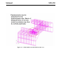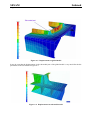
1
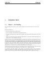
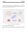
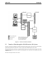
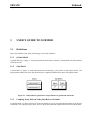
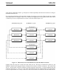
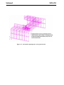
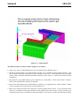
SESAM
USER MANUAL
Submod
Transfer Displacements from Global Model to SubModel
DET NORSKE VERITAS
SESAM
User Manual
Submod
Transfer Displacements from Global
Model to Sub-Model
November 1st, 2004
Valid from program version 3.0
Developed and marketed by
DET NORSKE VERITAS
DNV Software Report No.: 95-7013 / Revision 3, November 1st, 2004
Copyright © 2004 Det Norske Veritas
All rights reserved. No part of this book may be reproduced, in any form or by any means, without permission in
writing from the publisher.
Published by:
Det Norske Veritas
Veritasveien 1
N-1322 Høvik
Norway
Telephone:
Facsimile:
E-mail, sales:
E-mail, support:
Website:
+47 67 57 99 00
+47 67 57 72 72
software.sesam@dnv.com
software.support@dnv.com
www.dnvsoftware.com
If any person suffers loss or damage which is proved to have been caused by any negligent act or omission of Det Norske Veritas, then Det Norske Veritas shall pay
compensation to such person for his proved direct loss or damage. However, the compensation shall not exceed an amount equal to ten times the fee charged for the
service in question, provided that the maximum compensation shall never exceed USD 2 millions. In this provision “Det Norske Veritas” shall mean the Foundation
Det Norske Veritas as well as all its subsidiaries, directors, officers, employees, agents and any other acting on behalf of Det Norske Veritas.
Table of Contents
1
INTRODUCTION ............................................................................................................1-1
1.1
Submod — Sub-Modelling.............................................................................................................. 1-1
1.2
Submod in the SESAM System ....................................................................................................... 1-2
1.3
How to read the Manual................................................................................................................... 1-4
1.4
Status List ........................................................................................................................................ 1-4
1.5
Terminology and Notation............................................................................................................... 1-4
2
FEATURES OF SUBMOD ..............................................................................................2-1
2.1
Basic Features .................................................................................................................................. 2-1
2.2
Overview of Files............................................................................................................................. 2-2
2.3
Transfer of Data through the SESAM Interface File System .......................................................... 2-3
3
USER’S GUIDE TO SUBMOD.......................................................................................3-1
3.1
Definitions ....................................................................................................................................... 3-1
3.1.1
Global Model..................................................................................................................... 3-1
3.1.2
Sub-Model ......................................................................................................................... 3-1
3.1.3
Coupling Node (Driven Node) and Driven Variables....................................................... 3-1
3.1.4
Node-to-Node Coupling .................................................................................................... 3-2
3.1.5
Node-to-Element Coupling ............................................................................................... 3-2
3.1.6
Global Model File ............................................................................................................. 3-2
3.1.7
Sub-Model Files ................................................................................................................ 3-2
3.1.8
Coordinate Tolerance ........................................................................................................ 3-3
3.2
Steps in use of Submod.................................................................................................................... 3-3
3.2.1
Creation of a Global Model Results File........................................................................... 3-3
3.2.2
Creation of a Sub-Model ................................................................................................... 3-3
3.2.3
Running Submod to obtain the Boundary Displacements (Driven Variables) ................. 3-4
3.2.4
Creation of the Sub-Model Results File ............................................................................ 3-5
3.3
Typical Input to Submod ................................................................................................................. 3-5
3.4
Overlapping Display of Global Model and Sub-Model................................................................... 3-8
3.5
Results.............................................................................................................................................. 3-9
3.5.1
Files ................................................................................................................................... 3-9
3.5.2
Loadcases .......................................................................................................................... 3-9
3.5.3
Checking of Results from the Sub-Model Run ............................................................... 3-11
3.5.4
Overlapping Display of Results from Global Model and Sub-Model............................. 3-11
4
EXECUTION OF SUBMOD........................................................................................... 4-1
4.1
Program Environment...................................................................................................................... 4-1
4.2
Program Requirements..................................................................................................................... 4-1
4.2.1
Execution Time ................................................................................................................. 4-1
4.2.2
Storage Space .................................................................................................................... 4-1
4.3
Program Limitations ........................................................................................................................ 4-1
4.4
List of Elements Included in Submod Displacement Interpolation ................................................. 4-3
4.5
User Input - File Transfer between SESAM Manager and Submod ............................................... 4-5
5
INPUT DESCRIPTION ................................................................................................... 5-1
5.1
Input ................................................................................................................................................. 5-1
5.2
Detailed Description of Input........................................................................................................... 5-2
Run sub-modelling........................................................................................................................... 5-3
Global Superelement Scope............................................................................................................. 5-4
Analysis type -> User defined.......................................................................................................... 5-6
Coordinate Tolerance....................................................................................................................... 5-7
Global Project and Global top superelement ................................................................................... 5-8
Analysis type.................................................................................................................................... 5-9
Mix 3 and 6 DoF ............................................................................................................................ 5-10
APPENDIX A TUTORIAL EXAMPLES............................................................................ A-1
A1
Hatch Coaming ............................................................................................................................... A-1
REFERENCES.................................................................................................. REFERENCES-1
SESAM
Program version 3.0
Submod
01-NOV-2004
1
INTRODUCTION
1.1
Submod — Sub-Modelling
1-1
The sub-modelling technique allows a part of a (global) model to be re-analysed to produce more accurate results
locally.
The basic procedure is:
• Perform a (global) analysis of the structure.
• Create a sub-model with refined mesh of a region of interest.
• Interpolate the displacements computed for the global model and transfer to the boundary of the submodel.
• Analyse the sub-model using the interpolated displacements as prescribed (forced) displacements and
obtain a more accurate solution for the region.
To take advantage of the sub-modelling technique you do not need to make any provisions prior to the global analysis. It is an option you have after having performed a global analysis (e.g. the whole structure) and
it is evident that the results are not detailed enough in certain areas. You then create a new model (a submodel) for the area of interest and use Submod to interpolate and extract results from the global model and
to apply these onto the sub-model. (When creating the sub-model the geometry model input of the global
model may be adequate or at least be a good starting point.) The finite element mesh of the sub-model is
normally fine so as to produce more accurate results within the sub-model region.
Both the global model and sub-model may be superelement models, and the division into superelements and
the way the superelements are assembled in the two models may be completely different.
It is possible to make minor changes to the geometry of the sub-model to study the effect of alternative
designs or to model more accurately details that were neglected in the global analysis. This can only be
done provided the changes within the sub-model region have negligible effects on the global solution.
Submod
1-2
SESAM
01-NOV-2004
Program version 3.0
The sub-modelling program (Submod.exe) is executed through SESAM Manager. SESAM Manager creates an input file to Submod (SUBMOD.INP) based on the input parameters given in the sub-modelling
input window. This file may be updated and modified with additional commands through a text editor. The
format of the input file to Submod is described in Section 4.5.
1.1
Figure 1.1 Illustration of the sub-modelling technique
1.2
Submod in the SESAM System
SESAM is comprised of preprocessors, environmental analysis programs, structural analysis programs and
postprocessors. An overview of SESAM is shown in Figure 1.2 with Submod shown in the preprocessor
part.
SESAM
Program version 3.0
Submod
01-NOV-2004
1.2
Figure 1.2 SESAM overview
1-3
Submod
1-4
1.3
SESAM
01-NOV-2004
Program version 3.0
How to read the Manual
Chapter 2 FEATURES OF SUBMOD contains an introductory description of the major features and purpose of the program.
Chapter 3 USER’S GUIDE TO SUBMOD explains how to start the program and how to extract displacements from a global analysis and impose these on the sub-model. The section does not contain a full
description of all program features; a more complete understanding of Submod can only be obtained
through training in use while referring to Chapter 5 INPUT DESCRIPTION.
Chapter 4 EXECUTION OF SUBMOD contains more special information not intended for the new user
employing SESAM Manager to control his SESAM analysis. The section explains that Submod is a separate
program and how to start Submod from Manager. The files accessed by Submod are also explained. Built-in
and hardware dependent requirements and limitations are also described. In short, the more advanced user
will benefit by looking into this section.
Chapter 5 INPUT DESCRIPTION explains in detail all input to Submod.
Appendix A TUTORIAL EXAMPLES contains an example of use.
1.4
Status List
There exists for Submod (as for all other SESAM programs) a Status List providing additional information.
This may be:
• Reasons for update (new version)
• New features
• Errors found and corrected
• Documentation (tasks not yet described in this manual)
• Etc.
To look up information in the most updated version of the status list go to the support page of our website,
click the SESAM Status Lists link and log onto this service (contact us or your SESAM contact person for
login information).
1.5
Terminology and Notation
The terminology and notation in this manual are explained in Section 3.1 or when they first appear.
SESAM
Program version 3.0
Submod
01-NOV-2004
2
FEATURES OF SUBMOD
2.1
Basic Features
2-1
Submod is based on the results (displacements) from a ’global’ analysis. Displacements are read from the
result file of the global model by Submod and transferred to the boundary of a sub-model.
The user has to specify prescribed displacements on the boundary of his sub-model. In addition to this the
coordinates of the boundary of the sub-model must be found within the global model. Submod will perform
a search in the global model for the nodes specified as prescribed for all degrees of freedom (d.o.fs.) in the
sub-model. The coordinates must match in highest level superelement coordinate system.
It is also possible to have only some of the d.o.fs. in the boundary nodes as prescribed. To obtain this the
user has to give a particular command in the input file to Submod.
Both the global model and the sub-model may consist of one or more superelements. And the division into
superelements and the way the superelements are assembled in the two models may be completely different.
The superelement numbers to specify for Submod are the highest level superelement number in the global
model and the highest level superelement number in the sub-model.
Both node-to-node match and node-to-element match is available. See Analysis type in Section 5.2
For the node-to-element match it is possible with an automatic interpolation of displacements within shell
and solid elements in the global model. The interpolation is based on the element shape function of the elements used in the global model. The interpolation in shell elements may also be performed orthogonal to
the neutral plane of the elements (in the ’thickness direction’). This may be useful for a solid sub-model
when having a global shell model. Interpolation for beam elements are however only performed along the
neutral axis.
Interpolation in the global model is performed for all beam elements (2 and 3 node elements), all shell elements (3, 4, 6 and 8 node elements) and all solid element (4, 6, 8, 9, 15 and 20 node elements). This feature
involves the following sub-tasks in the program:
• Searching for the element in the global model and finding the normalised element coordinates (ξ, η and
ζ) of the matching elements that contains the node from the sub-model.
Submod
2-2
SESAM
01-NOV-2004
Program version 3.0
• Handling of element boundary situations in a proper manner. If the sub-model node is outside the global
model, the program will use a tolerance to check whether it is near enough to be defined as lying on the
element surface.
In order to reduce the number of first level superelements in the global model that Submod shall search
through to find matching elements containing the nodes, a scope feature has been implemented. This may
significantly reduce the CPU-time required.
To avoid searching in element types of no interest an option to exclude element types (beam, shell or solid)
from the search is included.
2.2
Overview of Files
Submod is reading displacements from the global model’s Results Interface File and writing ’boundary’ displacements on the sub-model’s first level T-files. Both the global model and the sub-model may consist of
one or more superelements.
Loads on the sub-model have to be taken either from Wadam (wave load program) or from a pre-processor
(Patran-Pre, GeniE, Prefem). In Patran-Pre you may choose to start modelling of the sub-model using the
global model’s database and only write out the sub-model part as the sub-model’s T-file. Loads generated
on the geometry will then automatically be transferred to the sub-model.
For loads to be generated by Wadam the global panel model may normally be used for the calculation of
wave loads on the sub-model.
SESAM
Program version 3.0
Submod
01-NOV-2004
2-3
2.1
Figure 2.1 The file environment of Submod
2.3
Transfer of Data through the SESAM Interface File System
The data read/written by Submod is transferred through the Input Interface File (the T-file) and the Global
model Results Interface File (the R-file). These are parts of the SESAM Interface File system.
The Input Interface File, the T-file, is a sequential ASCII character file with 80 character long records. The
straightforward definition of the file enables external programs to be connected to the SESAM system with
comparative ease.
The name of the Input Interface File will be:
Submod
2-4
SESAM
01-NOV-2004
Program version 3.0
prefixT#.FEM
where:
• ‘prefix’ is an optional character string that may or may not include a directory specification.
• ‘T’ is a mandatory character identifying this as an Input Interface File, a T-file, as opposed to a Loads
Interface File, L-file, which uses character L and a Results Interface File, R-file, which uses character R.
• ‘#’ is the superelement number, the identifier of the superelement.
• ‘FEM’ is a mandatory file extension.
Normally, the user may find it convenient to leave the prefix void. This is also the default condition.
An example of a name of an Input Interface File with prefix is:
ABCT5.FEM
SESAM
Program version 3.0
Submod
01-NOV-2004
3
USER’S GUIDE TO SUBMOD
3.1
Definitions
3-1
This section defines some of the terminology used in this document.
3.1.1
Global Model
A global model is a single- or multi-superelement model whose solution is interpolated onto the boundary
of the sub-model.
3.1.2
Sub-Model
A sub-model is a single- or multi-superelement model forming a part (detail) of the global model. The
superelement subdivision in the sub-model may be completely different from that of the global model.
3.1
Figure 3.1 Independent organisation of superlements in global and sub-model
3.1.3
Coupling Node (Driven Node) and Driven Variables
A coupling node is a node on first level in the sub-model to receive prescribed displacements in all degrees
of freedom. The coupling node defines where in the global model the displacement results should be trans-
Submod
3-2
SESAM
01-NOV-2004
Program version 3.0
ferred to the local model. The driven variables are the degrees of freedom in the coupling nodes. The values
of the driven variables are defined by interpolation of the global solution. Another name of the coupling
nodes is ’driven nodes’.
3.1.4
Node-to-Node Coupling
Node-to-node coupling means that the sub-model boundary nodes must match, within the tolerance specified, the nodes of the global model. Submod will use the nodal displacement values of the global model as
prescribed displacement values for the sub-model boundary nodes (the driven variables). If the first level
superlements in question of the global and local models have different coordinate system orientation then
the values of the driven variables will be transformed accordingly before transferred to the first level submodel Input Interface Files (T-files).
3.1.5
Node-to-Element Coupling
Node-to-element coupling means that the sub-model boundary nodes need not coincide with nodes of the
global model. Submod will use spatial (element shape function) interpolation of the global solution to calculate the prescribed displacement values for the sub-model boundary nodes (the driven variables). If the first
level superlements in question of the global and local models have different coordinate system orientation,
then the values of the driven variables will be transformed accordingly before transferred to the first level
sub-model Input Interface Files (T-files).
3.1.6
Global Model File
The global model file is the Results Interface File in ’SIN’-format of the global model. Displacements are
fetched from this file.
3.1.7
Sub-Model Files
The sub-model files are a set of Input Interface Files (T-files) containing the sub-model FE model, internal
loads and material data. Prescribed displacements will be written to these files. The name of highest level Tfile should be given as input to Submod, the remaining files will be nested up and read by the program. In
addition to the first level T-files internal loads from wave loading programs (like Wajac, Wadam) may also
be present on Load Interface Files (L-files).
If no internal loads exist, the prescribed displacements from Submod will be the only ’loads’ on the first
level T-files. When higher level superelements are used in the sub-model, the Presel load combination has to
be performed for the higher level superelements. The loads to combine are the prescribed displacements
subsequently written to the T-files by Submod.
Internal loads from Wajac / Wadam on repeated superelements in the sub-model is not possible due to the
loadcase numbering being different for repeated superelements in Wajac / Wadam and Submod.
SESAM
Program version 3.0
3.1.8
Submod
01-NOV-2004
3-3
Coordinate Tolerance
Node-to-Node Coupling
The coordinate tolerance for node matching must be given in the same unit as used by the global and submodel structures. The tolerance is the maximum allowable distance between a driven node in the sub-model
and a node in the global model.
Node-to-Element Coupling
For node-to-element coupling the coordinate tolerance is how far away a node in the sub-model may be
from an element in the global model and still be taken as being inside the element. But the use is a little bit
different from the use of the coordinate tolerance in the node-to-node coupling. For node-to-element coupling the coordinate tolerance is transformed to a relative tolerance for each element searched through in the
global model. This relative tolerance is calculated as the specified coordinate tolerance divided by the diagonal in a bounding box around each element in the global model. The consequence of this is that the actual
tolerance is much smaller out-of-plane than in-plane for most shell elements (in-plane dimensions are usually much larger than the thickness). This method with calculation of a relative tolerance will only map the
user’s tolerance exactly for a cube with sides parallel to the x-, y- and z-coordinate axes.
3.2
Steps in use of Submod
Independent analyses are performed on the global model and on the sub-model. The only link is the transfer
of displacement values for the driven variables.
3.2.1
Creation of a Global Model Results File
The user runs a ’global’ model calculation through Sestra, the linear Finite Element Method program, and
obtains a Results Interface File for this model. If the user then wants to:
• Study detailed stresses and displacements in a specific area of this model,
• Model some detail differently or more accurately,
• Model some detailswith solid elements instead of shell elements,
he may create a separate model for this part as described below.
3.2.2
Creation of a Sub-Model
By using GeniE, Patran-Pre, Prefem and/or Presel or a similar program, a sub-model of a part of the global
model may be created. This sub-model may consist of one or more superelements and the part of the global
model may be chosen without considering where the superelement boundaries are in the global model. The
boundaries of the sub-model to be given displacements taken from the results of the global model, have to
be given prescribed displacements type of boundary condition in the first level superelements of the submodel. These prescribed displacements will later be transferred from the results file of the global model.
The coordinates of the boundaries of the sub-model must have the same coordinates as the same positions in
the global model. The ’coordinates’ are in this context the coordinates in the highest level superelement of
Submod
3-4
SESAM
01-NOV-2004
Program version 3.0
the global model and the sub-model. This means that the user may model his sub-model in any convenient
coordinate system and later translate and rotate the sub-model into a higher level superelement to obtain the
same coordinates as in the global model. The first level superelement of the sub-model may for instance
have only one supernode which subsequently is included in the second level (’transformation-’) superelement. The mesh on the boundary of the sub-model may be different from the mesh of the same part of the
global model. The element types may also be different but the results will probably be best when using elements of the same order in the global model and the sub-model.
The internal loads of the sub-model must be modelled for the sub-model since only the effect of the loads
outside the sub-model will be accounted for by the boundary displacements. Internal wave loads, when
present, must also be modelled for the sub-model. If the sub-model is comprised of higher level superelements, then the load combination has to be performed for these higher level superelements of the submodel.
The load combination must be performed for sub-models comprised of higher level superelements even
when no internal loads exist yet. A warning is then given during the load combination in Presel:
** WARNING: LOAD CASE 1 ACCEPTED
BUT NOT YET DEFINED ON FIRST LEVEL
LOAD MUST BE GENERATED BY
LOAD PROGRAM
’LOAD PROGRAM’ is in this context Submod which will generate the values of the prescribed displacements for the different loadcases for the first level superelements.
Internal loads from Wadam on repeated superelements in the sub-model are not allowed due to the loadcase
numbering being different for repeated superelements in the L-files from Wadam and the T-files from Submod. When having ’n’ resultcases in the global model, Submod stores all the prescribed displacements for
position 1 of the repeated sub-model superelement as the first ’n’ loadcases on the superelement’s T-file.
The ’n’ loadcases with prescribed displacements from position 2 of the repeated sub-model superelement
are stored on the superelement T-file after the first ’n’ loadcases from position 1 of the repeated sub-model
superelement (as shown in Figure 3.4). When having ’n’ resultcases in the global model and 2 repetitions of
the sub-model superelement, Wadam will store the loads from position 1 of the repeated sub-model
superelement as loadcase number 1, 3, 5 ... (n/2-1) on the superelement L-file. The loads from postition
number 2 will by Wadam be stored as loadcase number 2, 4, 6 ... n, on the superelement L-file.
The sub-model may also be a modification of a superelement of the global model with, for instance, a finer
mesh than used in the superelement in the global model. The supernodes must then be re-defined as nodes
with prescribed displacements (also called driven or sub-model nodes).
3.2.3
Running Submod to obtain the Boundary Displacements (Driven Variables)
From the previous steps is obtained a Results Interface File (R-file) for the global model and Input Interface
File (T-file) from the sub-model. The sub-model has prescribed displacements defined for its boundaries but
no values of these prescribed displacements have been specified. By running Submod and specifying the
names of the results file of the global model and the T-file a new T-file is made. This file also contains the
values of the prescribed displacements on the boundary of the sub-model.
SESAM
Program version 3.0
3.2.4
Submod
01-NOV-2004
3-5
Creation of the Sub-Model Results File
The Input Interface File(s) (T-files) obtained for the sub-model by running Submod may be run through Sestra to create a results file for the sub-model. This results file may be postprocessed. If necessary, the submodel may be modified in GeniE, Patran-Pre, Prefem and/or Presel and re-run in Submod and Sestra.
3.3
Typical Input to Submod
In this section is shown a typical input for Submod specified in SESAM Manager with a short explanation
of the commands given.
Submod
3-6
SESAM
01-NOV-2004
3.2
Figure 3.2 Input to Submod in SESAM Manager
Program version 3.0
SESAM
Submod
Program version 3.0
01-NOV-2004
3-7
3.3
Figure 3.3 Details in Input of Global Superelement Scope (‘Specify’)
Typical input specification to a sub-model run:
• In Model menu in SESAM Manager select task Sub-modelling SUBMOD...
• Select Global project with results from global analysis of model
• Select Node-to-Element match. This means that the nodes of the sub-model do not need to coincide
with nodes of the global model. But the boundary nodes of the sub-model has to be ’inside’ an element
in the global model.
Submod
3-8
SESAM
01-NOV-2004
Program version 3.0
• Global model and local model has both either 3 degrees of freedom (dof.s) or 6 dof.s in the elements /
nodes (Mix 3 and 6 DoF off). 3 dof. elements are typically solid elements. While shell elements are
typically 6 dof. elements.
• Global top superelement number is automatically found by SESAM Manager from the global project.
• (Figure 3.2) Select All the superelements in the global model to search for geometric match of the
boundary nodes of the sub-model.
• (Figure 3.3) Select Global Superelement Scope number 10, index 1 as target in the global model for the
geometric search for match of the boundary nodes from the sub-model.
• The coordinate tolerance is set to 0.001 (metres). This is usually suitable for a model with dimensions
modelled in metres. The tolerance very much depends on the thickness of plates and structure elements.
In the Node-to-Element match the tolerance is converted inside the program to a relative tolerance for
each element in the global model. The consequence of this is that the actual tolerance is much smaller
out-of-plane than in-plane for most shell elements (in-plane dimensions are usually much larger than
thickness).
• Start Submod by clicking the Run Sub-modelling button.
• Sub-model boundary displacements are now fetched from the global model Results Interface File. The
displacements have been found either in nodes in the global model (Node-to-Node) or inside elements in
the global model (Node-to-Element).
• Finally run the sub-model (Tnn.FEM) in Sestra with the boundary displacements found from the global
model. And look upon the results in Xtract or in another post-processor. Compare the results with the
results of the global model to verify your run.
3.4
Overlapping Display of Global Model and Sub-Model
The method below makes it possible to see whether the sub-model is positioned correctly in the global
model.
The global model and the sub-model may be displayed in the same window by POSTFEM. The view of
both the global model and the sub-model in the same display in POSTFEM is obtained by using Prepost to
create the POSTFEM database from the Results Interface File for the global model and the T-file(s) from the
sub-model with the following commands:
1st run in Prepost:
OPEN SIN-DIRECT-ACCESS <glob_mod_prfx> <glob_mod_nam> OLD READ-ONLY
CREATE POSTFEM-DATABASE ’ ’ POSTFEM NEW ALL SEL-1...SEL-n
EXIT
2nd run in Prepost:
READ FEM-FORMATTED <sub_mod_prfx> <sub_mod_nam> ALL
CREATE POSTFEM-DATABASE ’ ’ POSTFEM OLD ALL T-1...T-m
EXIT
SESAM
Program version 3.0
Submod
01-NOV-2004
3-9
In the above commands we have ’n’ superelements in the global model which we want to put in the POSTFEM database and ’m’ superelements in the sub-model which we want to put in the POSTFEM database.
Instead of using the result file for the global model the T-file(s) from the global model may as well be used.
The input will then be similar to the input for the sub-model.
The <sub_mod_nam> should be the top level superelement of the sub-model, since this will result in an
automatic reading of all superelements in the sub-model hierarchy.
The ’BUILD’ command with ’ALL’ transformations is later used in POSTFEM to obtain both the global
model and the sub-model overlapping in the same POSTFEM model. In the example below, the commands
to be specified by the user are given in italic, while the leading text in POSTFEM and the explanatory comments are given in plain text. The assembly of the global model in the POSTFEM database is here named
’R10’ and the assembly of the sub-model is named T20-1. The different names of the models in POSTFEM
are shown when starting up POSTFEM:
>BUILD <new_name>
MODEL (OR GO) => R10 (assembly of GLOBAL MODEL)
TRANSFORMATIONS => ALL
MODEL (OR GO) => T20-1 (assembly of SUB-MODEL)
TRANSFORMATIONS => ALL
MODEL (OR GO) => GO
>VIEW MESH
The mesh of the global model and the sub-model overlapping each other will now be displayed in POSTFEM.
3.5
Results
3.5.1
Files
The Submod program will after a successful run have produced a new set of Input Interface Files (T-files),
each representing a superelement on the first level. The program convention is to use the same prefix and
name as the original T-files. On PC (MS Windows) the old T-file will get ’.bak’ added to the file type as
shown below:
MS Windows:
new file: <prefix>T<superelement-number>.FEM
old file: <prefix>T<superelement-number>.FEM.bak
3.5.2
Loadcases
The Submod program produces loadcases on first level in the sub-model which correspond to resultcases on
highest level in the global model. This means that when using superelements in the sub-model, load-combinations must be made for each higher level superelement by using Presel before performing the sub-model
analysis. These load combinations must usually be in a one to one correspondence. The first loadcase on
first level must be the first loadcase on highest level and so on up to the highest loadcase number. An exeption from this is for repeated superelements as shown in the figure below and described below.
The resultcase numbering found by Submod on the global Results Interface File is the internal sequential
resultcase numbering. Possible external result numbering made by Prepost or other programs are not recog-
Submod
3-10
SESAM
01-NOV-2004
Program version 3.0
nised. Result combinations made e.g. in Prepost are found sequentially after the basis resultcases on the global Results Interface File.
For repeated superelements in the sub-model, number of resultcases are used as offset for each new position
of the superement. For example; if there are 3 resultcases on highest level in the global model, there will be
3 loadcases per 1st level superelement occurrence in the sub-model (Figure 3.4).
3.4
Figure 3.4 Relation between Global Resultcases and Sub-Model Loadcases
Global results files may have results from more than one run. This may be obtained for instance by the
MERGE command in the program Prepost. Submod will account for all these resultcases. The results from
run no. 1 will be used as the first resultcases and the resultcases from run no. 2 will be numbered after the
resultcases from run no. 1 and so on. This means that Submod will write displacements on the sub-model’s
1st level superelements for as many resultcases as the sum of number of resultcases from the different runs.
SESAM
Program version 3.0
3.5.3
Submod
01-NOV-2004
3-11
Checking of Results from the Sub-Model Run
The user must ensure that the sub-modelling approach is applicable. There are no default protections when
utilising the sub-modelling technique - it is a matter of user’s judgement.
Examine contour plots of important variables near the boundaries of the sub-modeled region. If the contour
plots are created in e.g. POSTFEM with the same contour range, results will be valid if contour values coincide at the boundary of the sub-modeled region or in the same display as described below in Section 3.5.4.
In addition to this the boundary of the sub-model must be sufficiently far from the region of the sub-model
where the response changes (St. Venant’s Principle).
Some stress disturbances or consentrations on the boundary of the sub-model should, however, be expected
due to differences in the displacement shape functions of the sub-model and the global model.
3.5.4
Overlapping Display of Results from Global Model and Sub-Model
The method below makes it possible to verify the stresses and displacements on the boundary of the submodel.
The displacements and stresses of the global model and the sub-model may be displayed in the same window by POSTFEM. The view of both the global model and the sub-model in the same display in POSTFEM
is obtained by using Prepost to create the POSTFEM database from the two result files with the following
commands:
OPEN SIN-DIRECT-ACCESS <glob_mod_prfx> <glob_mod_nam> OLD READ-ONLY
CREATE POSTFEM-DATABASE ’ ’ POSTFEM NEW ALL SEL_1...SEL_n
OPEN SIN-DIRECT-ACCESS <sub_mod_prfx> <sub_mod_nam> OLD READ-ONLY
CREATE POSTFEM-DATABASE ’ ’ POSTFEM OLD ALL SEL_n+1...SEL_n+m
In the above commands we have ’n’ superelements in the global model which we want to put in the POSTFEM database and ’m’ superelements in the sub-model which we want to put in the POSTFEM database.
The BUILD command with ALL transformations is later used in POSTFEM to obtain both the global model
and the sub-model in the same POSTFEM model. The verification in this way of the boundary displacements being equal in the global model and the sub-model is particularly of great value.
Submod
3-12
SESAM
01-NOV-2004
3.5
Figure 3.5 Sub-model superimposed on the global model
Program version 3.0
SESAM
Program version 3.0
Submod
01-NOV-2004
4
EXECUTION OF SUBMOD
4.1
Program Environment
4-1
To be able to start the program Submod the executable Submod file should be located on the official
SESAM directory. The normal way of starting Submod is from the SESAM Manager program. The execution of Submod is started with the sub-command ’Sub-Modelling SUBMOD...’ of the ’Model’ command in
’SESAM Manager’.
4.2
Program Requirements
Submod is a relatively small program. The requirements are to a large degree dependent on the size of the
global model and the sub-model.
4.2.1
Execution Time
For a run where the global model has 22600 nodes, 41250 elements, 6 resultcases and the sub-model has
434000 nodes, 145000 elements, 1600 'coupling' nodes the clock time used with version 3.0-01 was a little
more than 6 hours. Both the global model and the sub-model were shell type structures with 6 dof. nodes.
The PC had 1 GB memory and a Pentium-4 1.6 Ghz processor.
4.2.2
Storage Space
The main storage space is from reading in the global model Results Interface File (R-file) plus the submodel’s Input Interface File (T-file). This will be the main content of the program’s database.
4.3
Program Limitations
The following constraints prevail in the present version of Submod:
• Coordinate system
Submod
4-2
SESAM
01-NOV-2004
Program version 3.0
The highest level superelement in the global model and the highest level superelement in the local submodel must have the same coordinate system.
The coupling nodes must not have local nodal transformations.
• Same units of global model and sub-model
The length units must be the same in the global model and the sub-model. The other units do not always
need to be the same, but it is recommended to avoid problems.
• One occurrence of sub-model
Only one occurrence of the sub-model will be accounted for in the sub-modelling module. Multiple occurrences must be solved by consecutive runs.
• Specification of coupling nodes
Coupling nodes must be defined as nodes with prescribed d.o.fs in the sub-model first level elements before starting Submod. Default setting is that only nodes where all degrees of freedom are prescribed will
be taken as coupling nodes. This may be re-defined in input to Submod to achieve that all nodes with any
d.o.fs prescribed will be taken as coupling nodes.
• Scope of superelements
A list of superelements in the global model assumed to contain coupling nodes of the sub-model. By default, all superelements will be scanned for nodes or elements to be coupled to, but the user may specify
superelements in the global model to scan or superelements not to scan for nodes or elements to get displacements from.
• Resultcases
All resultcases from the global model will be applied to the sub-model as 1st level ’local loadcases’. Repetition of 1st level superelement in sub-model ’n’ times will result in ’n’ times number of loadcases for
this 1st level superelement. If only some of the global loadcases are to be analysed, this may be achieved
by using Prepost to copy these resultcases to a new results SIN file for the global model before starting
Submod. Complex resultcases will be handled.
• Element types
For ’element node coupling’ all available shell elements, i.e. 3, 4, 6 and 8 node elements, and all available
solid elements, i.e. 4, 6, 8, 10, 15 and 20 node elements are implemented. The 2- and 3-node beam elements are also implemented, but the displacement may only be found (interpolated) along the neutral axis
of the beam elements.
• Coupling nodes
The coupling nodes of the sub-model must have 3 or 6 d.o.fs. Coupling nodes with 3 d.o.fs may match
solid elements or shell elements in the global model. The translational displacements will be put into the
sub-model’s T-file. It is the users responsibility to have the coupling nodes within or on the shell boundaries. Coupling nodes with 6 d.o.fs may match solid elements or shell elements in the global model. The
coupling nodes being in a solid element will only get displacements inserted in the three first (translational) degrees of freedom. The last three degrees of freedom will then have 0.0 as rotations. The node will
then be clamped with respect to rotations unless only the 3 translational degrees of freedom of the 6 d.o.f.s
have been specified as prescribed.
• Transfer of forces
SESAM
Submod
Program version 3.0
01-NOV-2004
4-3
The transfer of forces from e.g. a beam global model to a shell / solid sub-model are not implemented in
Submod.
4.4
List of Elements Included in Submod Displacement Interpolation
For ‘node-to-element coupling’ Table 4.1 shows the different elements to fetch displacements from in the
global model. The interpolation is using the element shape functions to find the displacement inside an element from the element’s nodal displacements. The interpolation performed for the different elements are:
• Beam elements
Interpolation of displacements and rotations is perfromed along the centerline of beam elements. The interpolation is implemented for both 2- and 3-node beams.
• Shell elements
Interpolation of displacements and rotations is performed in shell elements, both in the shell plane and in
the thickness of the shell elements. This means that a global model with shell elements can be used together with a solid sub-model with one or more solid elements in the ’thickness-direction’.
• Solid elements
Interpolation of displacements is performed in solid elements..
Table 4.1 Element Types
Element Type
Abbrev.
Description
No. of
NODES
D.O.F.
Straight Beam
BEAS
2-node straight beam
2
6
Curved Beam
BTSS
3-node curved beam
3
6
Flat triangular Shell
FTRS
Triangular flat thin shell
3
6
Flat Quadrilateral Shell
FQUS
Quadrilateral flat thin shell
with bubble modes in the
membrane part.
4
6
Curved triangular Shell
SCTS
Subparametric curved triangular thin/thick shell
6
6
Curved quadrilateral Shell
SCQS
Subparametric curved quatrilateral thin/thick shell
8
6
Curved triangular sandwich
Shell
MCTS
Subparametric curved multilayer triangular thin/thick
shell
6
6
Curved quadrilateral sandwich Shell
MCQS
Subparametric curved multilayer quadrilateral thin/thick
shell
8
6
Submod
SESAM
4-4
01-NOV-2004
Program version 3.0
Table 4.1 Element Types
Abbrev.
Description
No. of
NODES
D.O.F.
LCTS
Subparametric curved multilayer eccetntric triangular
thin/thick shell (stiffened
plates)
6
6
Curved quadrilateral eccentric sandwich Shell
LCQS
Subparametric curved multilayer eccetntric quadrilateral
thin/thick shell (stiffened
plates)
8
6
Solid ’flat’ Tetrahedron
TETR
Solid linear tetrahedron
4
3
Solid ’flat’ Wedge
TPRI
Solid linear wedge
6
3
Solid ’flat’ Hexahedron
LHEX
Solid linear hesahedron with
’bubble modes’
8
3
Solid ’curved’ Tetrahedron
ITET
Solid 2nd order isoparametric tetrahedron
10
3
Solid ’curved’ Wedge
IPRI
Solid 2nd order isoparametric wedge
15
3
Solid ’curved’ Hexahedron
IHEX
Solid 2nd order isoparametric hexahedron
20
3
Element Type
Curved triangular eccentric
sandwich Shell
SESAM
Submod
Program version 3.0
01-NOV-2004
4-5
4.1
Figure 4.1 Graphic illustration of shell and solid element types
4.5
User Input - File Transfer between SESAM Manager and Submod
The below information is for the particularly interested users.
This is a description of the Submod user input file made by SESAM Manager and read by Submod. The file
is written in FORTRAN formatted free format. The name of the User Input Transfer File is SUBMOD.INP.
Submod may be run separately if this file exists on the default directory before Submod is executed. The
following input commands are available:
Definintion of input file SUBMOD.INP:
%
% All text starting anywhere with a ’%’
Submod
SESAM
4-6
01-NOV-2004
Program version 3.0
character is a comment.
SMCOOTOL <nrec> <cotol>
% Coordinate tolerance
SMGLOPRF <nrec> <gprfix>
% Global results file prefix
SMGLONAM <nrec> <gname>
% Global results file name
SMMATELN <nrec> <match>
% Match node/node or node/element
SMMIXDOF <nrec> <mixdof>
% Mixed 3 to 6 DOF on or off
SMNTSRCH <nrec> <notsrch>
% Exclude search in beam/shell/solid
SMSKBNBX <nrec> <skip>
% Skip optimisation with boundary box search
SMSOMEDF <nrec> <somedf>
% Not all DOF.s driven in coupl.nodes?
SMSSCOPE <nrec> <iscpfl> <nsel> % Global super element scope
<supel> <index>
% Super element number and index if
<supel> <index>
% limited scope defined
:
<supel> <index>
SMSUBNAM <nrec> <sname>
% Interface file name for the sub-model
SMSUBPRF <nrec> <sprfix>
% Interface file prefix for the sub-model
SMENDFIL <nrec>
% End of file detected
Parameters:
<cotol>
real
Coordinate tolerance
<gname>
text*250
Global results file name
<gprfix>
text*250
Global results file prefix
<index>
integer
Super element index
<iscpfl>
integer
Scope flag, =0: All, =1: Include, =2: Exclude
<match>
integer
Matching node/element (=1) or node/node (=2)
<mixdof>
integer
Mixing of nodes with 3 and 6 dofs (1:off, 2:on)
<notsrch> integer
Value telling element class to exclude searching in.
'0' means search and '1' means not search 1000 - Do not search in beam elements
0100 - Do not search in membrane elements (not implemented)
0010 - Do not search in shell elements
0001 - Do not search in solid elements
1001 - Do not search in beam and solid elements a.s.o.
<nrec>
integer
Number of records in current command (=1 for most commands)
<nsel>
integer
Number of superelement selected in the scope
=0 if <iscpfl>=0
<skip>
integer
=1; Skip optimisation with boundary box search
SESAM
Program version 3.0
Submod
01-NOV-2004
=0; Optimise search in global model with boundary box
<sname>
text*250
Sub-model interface file name
<somedf>
char*5
Not all DOFs in coupl. nodes driven (= TRUE or FALSE)
<sprfix>
text*250
Sub-model interface file prefix
<supel>
integer
Super element type number
4-7
Submod
4-8
SESAM
01-NOV-2004
Program version 3.0
SESAM
Program version 3.0
5
Submod
01-NOV-2004
5-1
INPUT DESCRIPTION
The required input to Submod is specified in SESAM Manager. Messages about the execution status from
Submod will be displayed on the screen and in the file SUBMOD.MLG. In this file also more detailed
information about the run is printed.
5.1
Input
The following input have been implemented in SESAM Manager for execution in Submod.
Submod
5-2
SESAM
01-NOV-2004
5.1
Figure 5.1 Overview of Input to Submod in SESAM Manager
5.2
Detailed Description of Input
Below is a detailed description of the input options to Submod.
Program version 3.0
SESAM
Program version 3.0
Submod
01-NOV-2004
5-3
Run sub-modelling
5.2
Figure 5.2 Run sub-modelling
PURPOSE:
This action will execute the SUB-MODELLING process of searching for matching nodes in the global
model, finding displacements on the Results Interface File of the global model and writing these prescribed
nodal displacements on the modified Input Interface File (T-file) of the sub-model.
NOTES:
See also:
Global Superelement Scope
Coordinate Tolerance
Analysis type
Submod
SESAM
5-4
01-NOV-2004
Program version 3.0
Global Superelement Scope
5.3
Figure 5.3 Global Superelement Scope
PURPOSE:
To limit the first level superelements of the global model that can be accessed, in order to:
• Reduce CPU-time used in the search for displacements in the global model and increase program
response.
The scope limits all functions in the program that access the scope objects (i.e. the superelements), and can
therefore be used to guide the program in finding a correct solution faster than if the program worked on the
full global model.
PARAMETERS:
INCLUDE
The next values are included in the selection
EXCLUDE
The selected data in the list of Global Superelement Scope are
removed
OVERWRITE
The specifed Superelement Type and Index are overwriting the
selected data.
INSERT BEFORE
Insert the specifed Superelement Type and Index before the selected data
CLEAR
Remove all data from the Global Superelement Scope list
Superelement Type
First level superelement type in the global model
SESAM
Program version 3.0
Superelement Index
Submod
01-NOV-2004
5-5
First level superelement index number (’position number’) in
the global model (larger than 1 only if a superelement type is
repeated in the global model)
EXAMPLES:
5.4
Figure 5.4 Example of input to Global Superelement Scope
Submod will here search for match in the global model in superelement number 161 with index 1, superelement 161 with index 2 and superelement number 17 with index 1. If one or more of these superelements do
not exist in the global model a warning will be written out. If none of them exist, there will be nothing to
search in for Submod.
LIMITATIONS:
Maximum number of pair of superelement type numbers and indices is 1000
Submod
SESAM
5-6
01-NOV-2004
Program version 3.0
Analysis type -> User defined
5.5
Figure 5.5 Analysis type -> User defined
PURPOSE:
The input file to Submod may be made directly by the user or the input file may be generated by SESAM
Manager and modified afterwards by the user. For description of the format and commands to the input file
see Section 4.5 User Input - File Transfer between SESAM Manager and Submod
SESAM
Program version 3.0
Submod
01-NOV-2004
5-7
Coordinate Tolerance
5.6
Figure 5.6 Coordinate Tolerance
PURPOSE:
The command specifies the coordinate tolerance used for deciding the tolerance for node match or match
with elements of global model when ’Matching of nodes -> Node-to-Element’ has been chosen. The tolerance describes the distance between two points in 3D-space, to decide whether two points (nodes) have the
same location or not or for deciding whether a node lies inside an element or not. The use of the coordinate
tolerance is a bit different when used in the node-to-element coupling than when used in the node-to-node
coupling. For details see Section 3.1.8 Coordinate Tolerance. The coordinate tolerance is given in the same
unit as the coordinates. The default value is 0.001. This value is suitable when the model has length unit
’meter’. If the length unit is ’mm’ a suitable tolerance will be 1.0 instead.
PARAMETERS:
Coordinate Tolerance
NOTES:
See also:
Analysis type
Coordinate tolerance used to search for ’coupling nodes’ having the same coordinate as a node in the global model or being
inside an element in the global model
Submod
SESAM
5-8
01-NOV-2004
Program version 3.0
Global Project and Global top superelement
5.7
Figure 5.7 Global Project and Global top superelement
PURPOSE:
Here the user selects the global project where the global model Results Interface File is found. The Results
Interface File has to be a SIN (NORSAM) formatted file. If the global model is a superelement, the number
of the highest level superelement in the global analysis shall be written. Normally SESAM Manager will
know the superelement number of the global results file and put this in automatically.
The global project must exist in advance and be a project ’parallel’ to the sub-model project.
PARAMETERS:
Global top superelement
Superelement number for the top level superelement in the global model
SESAM
Program version 3.0
Submod
01-NOV-2004
5-9
Analysis type
5.8
Figure 5.8 Analysis type
PURPOSE:
Here the user selects node-to-node coupling or node-to-element coupling between the boundary nodes of the
sub-model and the nodes or elements in the global model. The default is node-to-element coupling. Nodeto-element coupling means that the sub-model boundary nodes need not align with mesh lines in the global
model. Submod will use spatial (element shape functions) interpolation of the global solution to calculate
the values for the sub-model boundary nodes. For shell elements the rotation in the nodes are also considered when calculating displacements outside the element neutral plane.
PARAMETERS:
Node-to-Node
The coupling nodes in the sub-model will be coupled to nodes
in the global model
Node-to-Element
The coupling nodes in the sub-model will be coupled to displacement fields in elements in the global model
NOTES:
See also:
Coordinate Tolerance
Submod
5-10
SESAM
01-NOV-2004
Program version 3.0
Mix 3 and 6 DoF
5.9
Figure 5.9 Mix 3 and 6 DoF
PURPOSE:
This option allows shell-to-solid sub-modelling with nodes in the sub-model with 3 degrees of freedom
(d.o.f.) and nodes in the global model with 6 d.o.f. Nodes with 3 d.o.f. in the sub-model may also be coupled
to shell elements with 6 d.o.f.
The coupling of nodes in the sub-model with 6 d.o.f. to nodes or elements in the global model with 3 d.o.f.
will also be allowed. But the user should then observe that the prescribed displacements in the remaining 3
rotational degrees of freedom will be set equal to 0.0 (fixed) unless the user has specified only prescribed
displacements for the three translational d.o.fs for these nodes on first level in the sub-model. See the next
paragraph.
It is also possible to have coupling nodes in the sub-model where only some d.o.f. are defined as coupling
degrees of freedom. The command to make this possible in Submod is at the moment only available as
direct input in the SUBMOD.INP file. For information on how to do this, see the command SMSOMEDF
in Section 4.5 User Input - File Transfer between SESAM Manager and Submod.
The default is that the ‘Mix 3 and 6 DoF’ option is set to OFF.
PARAMETERS:
On
The coupling nodes in the sub-model will be coupled to nodes
in the global model
Off
The coupling nodes in the sub-model will be coupled to displacement fields in elements in the global model
SESAM
Program version 3.0
Submod
01-NOV-2004
5.10
Figure 5.10 Shell to Solid Sub-Modelling
5-11
Submod
5-12
SESAM
01-NOV-2004
Program version 3.0
SESAM
Submod
Program version 3.0
APPENDIX A
01-NOV-2004
A-1
TUTORIAL EXAMPLES
One tutorial example is presented here.
A1
Hatch Coaming
The global model is a superemenet model with the superelement hierarchy shown in the figure below:
A.1
Figure A.1 Global superelement hierarchy
This model contains of 3 first level superelements (1, 2 and 3). These superelements are coupled together in
superelement number 10 on 2nd level. Finally superelement 10 is coupled together with a mirrored
superelement 10 into 3rd level superelement number 100. The region where the sub-model is to be positioned contains parts of superelement 1, 2 and 3 on 1st level. This is indicated in Figure A.2.
Submod
A-2
SESAM
01-NOV-2004
Program version 3.0
A.2
Figure A.2 Global Model
The different tasks to be done and the sequence is as follows:
1 Open a new project in SESAM Manager for your global model (’Hatch-Coarse’).
2 Model the global model as one superelement structure or as a multilevel superelement structure. This
may be done with GeniE, Patran-Pre, Prefem, Wadam and/or Presel. The output from these programs
will be T-files with finite element information (elements, nodes, loads a.s.o.) and L-files with wave load
information.
3 Run Sestra for your global model to get a results file (e.g. ’R100.SIN’). Sestra will read the T- and possible L-files and make the result file ’R100.SIN’.
4 Open a new sub-model project (’Hatch-Detail’) ’parallel’ to your global project. With ’parallel’ is meant
a project with the same root-directory as the global project.
5 Make your sub-model with GeniE, Patran-Pre, Prefem, Wadam and/or Presel. If your model has been
made in a coordinate system other than that for the global model, Presel may be used to position your
sub-model to the correct coordinates in the global model. If you want to use the superelement technique
SESAM
Program version 3.0
Submod
01-NOV-2004
A-3
(Presel) to do this, remember to make at least one ’dummy’ supernode on your 1st level sub-model
superelement.
The local ’internal’ loads on your sub-model has to be modelled in the sub-model even if they are present
on your global model. It is only the displacements in the ’coupling nodes’ that is found from the global
model. However, usually the local internal loads like water pressure are not very important on local submodels. In some cases the internal loads may be achieved directly from the geometry of your global model by using the global model in the preprosessor as basis for your sub-model.
6 Run Submod from the SESAM Manager menu ’Model -> Sub-modelling SUBMOD...’ Remember to
change the ’Coordinate tolerance’ if your model does not have length unit ’meters’.
7 Check your sub-model run in the information file from Submod ’SUBMOD.MLG’. The displacements
from the global model have now been writtten to the ’coupling nodes’ on your 1st level T-file(s). The
displacements are written to the BNDISPL records on the T-file (’T1.FEM’). Only the first level T-files
of the sub-model are modified by Submod.
8 Run Sestra for your sub-model to get a results file (e.g. ’R1.SIN’). Sestra will read the T- and possible Lfiles and make the results file ’R1.SIN’ for your sub-model.
9 Check the results for your sub-model in Xtract or another postprocessor program. The stresses on the
boundaries may be locally high, but this is usual just a local problem. The stress level should generally
reflect the same stresses in the global model.
A.3
Figure A.3 Sub-Model
Submod
A-4
SESAM
01-NOV-2004
A.4
Figure A.4 Global model and sub-model in same view
Program version 3.0
SESAM
Program version 3.0
Submod
01-NOV-2004
A-5
A.5
Figure A.5 Displacements in global model
It may be seen that the displacements in the sub-model part of the global model is very much like the displacements in the sub-model in Figure A.6
A.6
Figure A.6 Displacements in sub-model model
Submod
A-6
SESAM
01-NOV-2004
A.7
Figure A.7 Von Mises element stresses in global model
A.8
Figure A.8 Von Mises element stresses in sub-model
Program version 3.0
SESAM
Program version 3.0
Submod
01-NOV-2004
REFERENCES
1 SESAM Input Interface File, File Description
Report no. 89-7012
Det Norske Veritas
November 1996
REFERENCES-1
Submod
REFERENCES-2
SESAM
01-NOV-2004
Program version 3.0