1
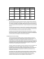
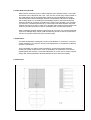
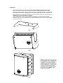
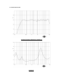
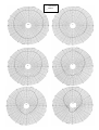
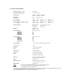
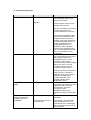
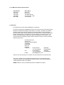
i6 AW & i6T AW USER MANUAL CONTENTS 1. Introduction 2. Unpacking 3. Connectors/Cabling 4. Polarity Checking 5. Amplification & Power Handling 6. Power Selection 7. Equalisation 8. Dimensions 9. Hardware 10. Performance Data 11. Technical Specifications 12. Troubleshooting Guide 13. i6 Recommended Service Parts & Accessories 14. Warranty 15. Declaration of Conformity 1. Introduction Designed for a wide variety of sound reinforcement applications the Tannoy i6 AW (All Weather) is an ultra compact loudspeaker system capable of delivering high sound pressure levels with extremely low distortion, resulting in outstanding clarity, definition and detail. A truly universal solution, the i6 AW offers outstanding durability and resistance to scuffs and knocks. Able to deliver consistent performance under a wide range of adverse conditions the i6 AW is suited to applications indoors or out, whether it be a theme bar or theme park. Available in dark grey or white the i6 AW will effectively blend into most backgrounds. Utilisation of the point source Dual Concentric loudspeaker allows the i6 AW to be mounted on a wall or ceiling in either horizontal or vertical orientations without affecting its performance. A range of hardware options ensures simple and effective installation. Also available with built in line transformer (i6T AW). The i6 AW comprises one 6.5 inch (165mm) Dual Concentric driver in which the low frequency (LF) and high frequency (HF) sources are coincidentally aligned to a point source, resulting in a smooth uniform frequency response over a wide area of coverage. The sophisticated CAD designed waveguide combines 90 degree conical dispersion and excellent acoustic impedance characteristics. For applications requiring extended low frequency enhancement, a range of Tannoy sub-bass systems are available and can be used in conjunction with the i6 AW. 2. Unpacking Every Tannoy i6 AW product is carefully inspected before packing. After unpacking your loudspeakers, please inspect for any exterior physical damage, and save the carton and any relevant packaging materials in case the loudspeaker again requires packing and shipping. In the event that damage has been sustained in transit notify your dealer immediately. 3. Connectors/Cabling The i6AW has two screw terminals for connection to the amplifier, these are gold plated in order to improve electrical conductivity and to prevent oxidisation. These terminals are capable of accepting cables with a conductor diameter of up to 6mm. Red is Positive Black is Negative Cable choice consists mainly of selecting the correct cross sectional area in relation to the cable length and the load impedance. A small cross sectional area would increase the cables series resistance, inducing power loss and response variations (damping factor). Connectors should be wired with a minimum of 2.5 sq. mm (12 gauge) cable. This will be perfectly satisfactory under normal conditions. In the case of very long cable runs the wire size should exceed this, refer to the following table for guidance:- CABLE RUN (m) C.S.A. OF EACH CONDUCTOR (mm) CABLE RESISTANCE Ω % POWER LOSS INTO 8Ω Ω LOAD % POWER LOSS INTO 4Ω Ω LOAD 10 2.5 4.0 6.0 2.5 4.0 6.0 2.5 4.0 6.0 2.5 4.0 6.0 0.14 0.09 0.06 0.35 0.22 0.14 0.69 0.43 0.29 1.38 0.86 0.58 1.7 1.1 0.73 4.3 2.7 1.8 8.6 5.4 3.6 17.0 11.0 7.2 3.5 2.2 1.5 8.6 5.4 3.6 17.0 11.0 7.2 35.0 22.0 14.0 25 50 100 4. Polarity Checking It is most important to check the polarity of the wiring. A simple method of doing this without a pulse based polarity checker for LF units is as follows: Connect two wires to the +ve and -ve terminals of a PP3 battery. Apply the wire which is connected to the +ve terminal of the battery to the speaker cable leg which you believe to be connected to the red speaker terminal and likewise the -ve leg of the battery to the black speaker terminal If you have wired it correctly the LF drive unit will move forward, indicating the wiring is correct. All that remains now is to connect the +ve speaker lead to the +ve terminal on the amplifier and the -ve lead to the -ve terminal on the amplifier. If however the LF driver moves backwards, the input connections need to be inverted. If problems are encountered, inspect the cable wiring in the first instance. It should also be noted that different amplifier manufacturers utilise different pin configurations and polarity conventions, if you are using amplifiers from more than one manufacturer, check the polarity at the amplifiers as well as the loudspeakers. 5. Amplification & Power Handling As with all professional loudspeaker systems, the power handling is a function of voice coil thermal capacity. Care should be taken to avoid running the amplifier into clip (clipping is the end result of overdriving any amplifier). Damage to the loudspeaker will be sustained if the amplifier is driven into clip for any extended period of time. Headroom of at least 3dB should be allowed. When evaluating an amplifier, it is important to take into account its behaviour under low impedance load conditions. A loudspeaker system is highly reactive and with transient signals it can require more current than the nominal impedance would indicate. Generally a higher power amplifier running free of distortion will do less damage to the loudspeaker than a lower power amplifier continually clipping. It is also worth remembering that a high powered amplifier running at less than 90% of output power generally sounds a lot better than a lower power amplifier running at 100%. An amplifier with insufficient drive capability will not allow the full performance of the loudspeaker to be realised. It is important when using different manufacturers amplifiers in a single installation that the have very closely matched gains, the variation should be less than +/- 0.5dB. This precaution is important to the overall system balance when only a single compressor/limiter or active crossover is being used with multiple cabinets; it is therefore recommended that the same amplifiers be used throughout. 6. Power Selection (i6T AW) Determine the maximum power in watts needed at each speaker location. The i6 AW transformer can be tapped at 30w, 15w, 7.5w, & 3.75w via the rotary switch located on the metal plate at rear of the loudspeaker. When the relevant tappings have been selected add the individual wattages required at all speakers and select an amplifier with a rating equal to or exceeding the total wattage required. All of the transformer primaries should be connected in parallel to the output of this amplifier. If for example, you select the 7.5-watt transformer tap, it means that at full rated amplifier output the speaker will receive the full 7.5 watts. If the amplifier gain is reduced each speaker will receive a proportional amount of power, maintaining the overall system balance. When calculating amplifier wattage requirements for a system, it is recommended that a generous wattage safety margin (3dB of headroom) be left so that the system does not have to operate continuously at its full rated output 7. Equalisation The i6AW loudspeaker is designed to need no equalisation or correction to overcome system limitations. As a result, it will only need equalisation to compensate for difficult acoustic environments. Over equalisation can reduce system headroom, and introduce phase distortion resulting in greater problems than cures. If equalisation is required then it should be applied gently and smoothly. The i6AW loudspeaker is a point source, phase coherent design and violent equalisation will be detrimental to the overall sound quality. 8. Dimensions 9. Hardware The i6AW can be wall or ceiling mounted using the MB6 (optional) bracket (fig 1.) which is designed to offer the maximum flexibility in selecting the desired angles. The MB6 is supplied with M8 bolts for fixing to the loudspeaker (fig1.& 2). After fixing the bracket to the wall or ceiling remove the plastic plugs from the top and bottom of the loudspeaker. Position the cabinet at the required angle as shown and tighten the M8 Bolts to fix the loudspeaker in position. The loudspeaker can be mounted either horizontally or vertically using the MB6 bracket (fig1.& 2.). This product has four M6 threaded holes in the rear of the cabinet for other bracketry. Fig 1. Fig 2. NOTE: The installation of this product must be carried out in conformity with local building codes and standards. If necessary consult your local safety standards officer before installing any product. Alternatively, check any laws or bylaws.Tannoy will not be held responsible for any damages caused by the improper installation of any bracket or loudspeaker. Fig 3. 10. Performance Data Anechoic Frequency Response, 1watt @ 1m Impedance ---- Hororizontal ___Vertical 500Hz 1k 4k 2k 16k 8k 11. Technical Specifications Frequency response (1) +/- 3dB 70Hz - 20kHz Recommended Amplifier Power up to 180 watt / 8 ohm Power Handling Average(2) Programme Peak (10ms) 90 watt 180 watt 360 watt Sensitivity (1) 2.83 volt @ 1m 90dB 93dB (half space) Maximum SPL (3) @ 1m Average 109dB Peak 115dB Average (half space) 112dB Peak (half space) 118dB Maximum SPL (3) With THP30 Transformer @ 1m Average 104 dB Peak 110dB Average (half space) 107dB Peak (half space) 113dB Transformer (i6T AW) Max. Insertion loss Primary Taps Voltage Taps Impedance Nominal Minimum DI Averaged (PCQ) @ 1kHz (ISO) @ 2kHz (ISO) @ 4kHz (ISO) @ 8kHz (ISO) @ 16kHz (ISO) 7.41, 250 Hz - 16 kHz 6.1 6.3 9.7 9.6 13.6 Q Averaged (PCQ) @ 1kHz (ISO) @ 2kHz (ISO) @ 4kHz (ISO) @ 8kHz (ISO) @ 16kHz (ISO) 7.74, 250 Hz - 16 kHz 4.1 4.3 9.3 9.1 22.9 Driver Complement 1 x 6.5” (165mm) Constant Directivity Dual Concentric Crossover Point 1.6 kHz Enclosure 11 litre, vented polyethylene Finish Charcoal or White Protective Grille Perforated Aluminium Connectors 2 x 4mm 5way binding posts Fittings 2 x M8 inserts for Yolk Bracket 4 x M6 inserts on rear of cabinet Dimensions 344mm (H) x 250mm (W) x 225mm (D) 13.54” (H) x 9.84” (W) x 8.86” (D) Weight 5.5 Kg (12.1 lbs) Shipping Dimensions 400mm (H) x 500mm (W) x 300mm (D) 15.75” (H) x 19.69” (W) x 11.8” (D) Shipping Weight 13Kg (28.6 lbs.) NOTES: 1.1 dB 35Hz – 21kHz +/- 2dB 30,15, 7,1.5 watt 70.7V & 100V 8 ohm 6 ohm (1) Average over stated bandwidth. Measured at 1m on axis, in an anechoic chamber. (2) Long term power handling capacity as defined in EIA standard RS - 426A. (3) Unweighted pink noise input, measured at 1m Tannoy operates a policy of continuous research and development. The introduction of new materials or manufacturing methods will always equal or exceed the published specifications which Tannoy reserve the right to alter without prior notice. Please verify the latest specifications when dealing with critical applications. 12. Troubleshooting Guide Symptom No Output From Speakers Possible Cause Broken Speaker Cables(s) Action Check the electrical continuity of the loudspeaker cables, and replace if necessary. Amplifier Check the gain controls on the amplifier are turned up. Be sure the amplifier is receiving an input signal (check the “signal” indicators on the amp). Intermittent Output Poor Connection Poor Low Frequency Output “Out of phase” connection Irregular sounds such as buzzing and humming emanating from the loudspeaker Poor system grounding Faulty electronic device in the signal chain Connect the loudspeaker cable which has no output to another amplifier channel you know is working, make sure signal is fed to the new amplifier channel. If output is obtained from the loudspeakers(s) then the problem is with the amplifier channel or input signal leads. If this is not the case then the fault may lie in the cabling or the loudspeaker. Check the loudspeaker cabling has a good electrical connection with amplifier outputs and loudspeaker inputs. A bad connection can increase resistance which will substantially reduce the output, or make “cracking” noises which are unrelated to signal content If using multi-strand loudspeaker cable, be sure no strands of cable are causing short circuits between the positive and negative terminals of the amplifier outputs and/or loudspeaker inputs. When two speakers are connected “out of phase”, the low frequencies will virtually be cancelled out. Check the connections at the amplifier/speaker paying attention to polarity. (see section 4). Check and correct system grounding. The speaker cannot generate these sounds on its own. It is most likely there is a fault with a piece of electronic equipment in the signal path. 13. I6 AW Service Parts & Accessories Part Number 7900 0411 7900 0412 7900 0725 7300 0684 8000 0920 Description Driver Kit Recone Kit HF Diaphragm Kit Crossover Kit - 1282 Yoke Bracket 14. Warranty No maintenance of the i6 AW loudspeaker is necessary. All Tannoy professional loudspeaker products are covered by a 5 year warranty from the date of manufacture subject to the absence of misuse, overload or accidental damage. Claims will not be considered is the serial number has been altered or removed. Work under warranty should only be carried out by a Tannoy Professional dealer or service agent. This warranty in no way affects your statutory rights. For further information please contact your dealer or distributor in your country. If you cannot locate your distributor please contact Customer Services, Tannoy Ltd at the address given below. Customer Services Tannoy Ltd. Rosehall Industrial Estate Coatbridge Strathclyde ML5 4TF Scotland Telephone: 01236 420199 +44 1236 420199 Fax: 01236 428230 +44 1236 428230 E-Mail: prosales@tannoy.com (National) (International) (National) (International) DO NOT SHIP ANY PRODUCT TO TANNOY WITHOUT PREVIOUS AUTHORISATION Our policy commits us to incorporating improvements to our products through continuous research and development. Please confirm current specifications for critical applications with your supplier. EASE Data for Tannoy Professional products available on request. Declaration of Conformity The following apparatus is/are manufactured in the United Kingdom by Tannoy Ltd of Rosehall Industrial estate, Coatbridge, Scotland, ML5 4TF and conform(s) to the protection requirements of the European Electromagnetic Compatibility Standards and Directives relevant to Domestic Electrical Equipment. The apparatus is designed and constructed such that electromagnetic disturbances generated do not exceed levels allowing radio and telecommunications equipment and other apparatus to operate as intended, and, the apparatus has an adequate level of intrinsic immunity to electromagnetic disturbance to enable operation as specified and intended. Details of the Apparatus: Tannoy Contractor Loudspeaker Model Number: i6 Associated Technical File: EMCi6 Applicable Standards: EN 50081-1 Emission EN 50082-1 Immunity Signed: Position: Technical Manager Tannoy Professional Date: 26 Apr. 99 Tannoy Loudspeakers are manufactured in Great Britain by : Tannoy Ltd, Rosehall Industrial Estate, Coatbridge, Strathclyde, ML5 4TF, SCOTLAND Telephone: +44 (0)1236 420199 Fax: +44 (0)1236 428230 Internet: http://www.tannoy.com Tannoy North America Inc. 335 Gage Avenue, Suite 1, Kitchener, Ontario, CANADA, N2M 5E1 Telephone: (519) 745 1158 Fax: (519) 745 2364 Tannoy Nederland BV, Anthonetta Kuijistratt 19, 3066GS, Rotterdam THE NETHERLANDS Telephone: (015) 2124034 Fax: (015) 2125213 Issue 1 Part No. 6481 0307 th GH 19 April 1999