1
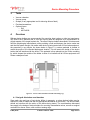
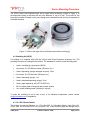
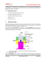
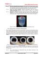
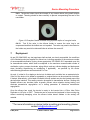
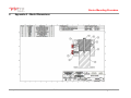
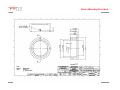
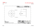
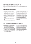
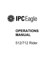
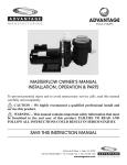
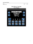
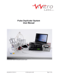
Device Mounting
Procedure
6 May 2015
© ViVitro Labs Inc. 2015
Page 1 of 19
Device Mounting Procedure
Table of Contents
1.
References .................................................................................................................... 3
2.
Materials ........................................................................................................................ 3
3.
Tools ............................................................................................................................. 4
4.
Overview ....................................................................................................................... 4
4.1 Design & fabrication considerations ....................................................................... 4
4.2 Moulding kit (05532)............................................................................................... 5
4.3 GI-1100 Silicone Rubber ........................................................................................ 5
5.
Mould Assembly ............................................................................................................ 6
5.1. Holders With a Step .............................................................................................. 6
5.2. Creating Mould Mandrel ........................................................................................ 7
5.2.1. Transcatheter Valves .................................................................................. 7
5.2.2. Surgical Valves – Mechanical & Bioprosthetic ........................................... 8
5.2.3. Occluders and Other devices.....................................................................10
5.3. Building the Mould ................................................................................................12
6.
Creating a Holder .........................................................................................................13
6.1. Selecting Silicone .................................................................................................13
6.2. Mixing Silicone .....................................................................................................13
6.3. De-aerating Mixture ..............................................................................................13
6.4. Moulding & Trimming Holders ..............................................................................14
7.
Deployment ..................................................................................................................15
8.
Appendix A – Mould Dimensions ..................................................................................16
6 May 2015
© ViVitro Labs Inc. 2015
Page 2 of 19
Device Mounting Procedure
Device Mounting Procedure
The following procedure describes the method for moulding silicone device holder rings and
mounting devices for the ViVitro Labs Pulse Duplicator
Duplicator, HiCycle, and RWT. This
is method allows
the device to be mounted and removed without altering or damaging the device.. For information
on how to purchase pre-made,
made, custom device holders, please contact info@vivitrolabs.com.
info@vivitrolabs.
Figure 1. CoreValve (left) and Perimount Valve (right) in ViVitro Labs standard holders.
1.
References
•
•
•
•
2.
ISO 5840-3:2013 – Heart valve substitutes implanted by transcatheter techniques
ISO 5840:2005 - Cardiovascular Implants
Implants- Cardiac Valve Prostheses, Fourth edition
Pulse Duplicator User Manual (17473-B)
HiCycle User Manual (17478
(17478-A.2)
Materials
•
•
•
ViVitro Labs Standard Holder Moulding Kit (05532 - See Section 4.2)
Gloves
Optional Items:
o Large Atrium Valve Holder Assembly (21011)
o Condensation Putty – Henry Schein P/N 1013318 (http://www.henryschein.com/)
o Condensation Putty Catalyst – Henry Schein P/N 8960890
(http://www.henryschein.com/)
o Plaster – Smooth--On Smooth-Cast® 300 (http://www.smooth-on.com/)
on.com/)
o Flowable Silicone Sealant – Dow
ow Corning® 734 Flowable Sealant
(http://www.dowcorning.com/
http://www.dowcorning.com/)
6 May 2015
© ViVitro Labs Inc. 2015
Page 3 of 19
Device Mounting Procedure
3.
Tools
•
•
•
•
•
4.
Vacuum chamber
Vacuum pump
Scalpel (or any appropriate tool for trimming silicone flash)
Flat-head screwdriver
Optional Items:
o Drill
o #25 Drill Bit
Overview
Silicone device holders are recommended for mounting heart valves or other test specimens.
ISO 5840-3:2013 specifies that in vitro test fixturing shall be designed to be representative of
critical aspects of the target implant site. The silicone device holders described in this document
fulfill the physiological requirements, while providing a fluid seal between the device under test
and the test system flanges. No matter what device is being tested with ViVitro Labs equipment,
the procedure is very simple. As shown below in Figure 2, a custom pedestal is created to
match the profile of the intended deployment location. This will create the inside of the device
holder that will interface with the device. This pedestal is then placed into the ViVitro moulding
jig, which shapes the outside of the holder to allow it to interface will all ViVitro equipment and
create a waterproof seal.
Figure 2. ViVitro Labs Standard Holder Moulding Jig.
4.1 Design & fabrication considerations
Since each size and type of test device differs in geometry, a unique device holder may be
required in order to match and seal the appropriate boundaries on the device. The device holder
should not interfere with the action of the device being tested. The considerations discussed
here apply to the design of device holders for mounting transcatheter valves, as well as surgical
mechanical or tissue valves, with or without sewing rings.
6 May 2015
© ViVitro Labs Inc. 2015
Page 4 of 19
Device Mounting Procedure
The ViVitro Labs Pulse Duplicator also has a Large Atrium accessory, shown in Figure 3, to
accommodate testing on devices with an outer diameter of up to 55 mm. The mould for the
Large Atrium holder is based on the same design as the standard mould, but is just expanded to
a broader diameter.
Figure 3. ViVitro Labs large atrium attachment and holder moulding jig.
4.2 Moulding kit (05532)
A moulding kit is supplied with both the HiCycle and Pulse Duplicator accessory kits. The
moulding kit assists in making device holders. The standard kit consists of the following parts:
•
1 each, moulding jig components (06234)
•
1.8 pounds, GI-1100 Silicone rubber (Silicones, Inc.)
•
1 each, dispensing syringe (enlarged end port), 35 ml
•
0.2 pounds, GI-1100 Activator (Silicones, Inc.)
•
1 each, dispensing syringe, 1 ml
•
1 each, standard dispensing syringe, 35 ml
•
1 each, gage tapered tip, #5116TT-B (EFD Inc.)
•
100 ml, waxed paper mixing cup and wooden spatula
•
1 ml, mould release grease (Vaseline) in syringe
To order the moulding kit on its own or any of its individual components, please contact
info@vivitrolabs.com for assistance.
4.3 GI-1100 Silicone Rubber
This rubber is made by Silicones, Inc., P.O. Box 363, 211 Woodbine Street, High Point, NC,
27260, USA. Ph (919) 886-5018, Fax: (919) 886-7122. It has extremely high tear strength and is
6 May 2015
© ViVitro Labs Inc. 2015
Page 5 of 19
Device Mounting Procedure
a, highly elastic, two-component, tin catalyzed RTV (Room Temperature Vulcanizing) silicone
rubber. Silicones, Inc. produces a variety of other silicone mixtures, if another Shore hardness is
desired (see section 6.1 for details).
GI-1100 Specifications include:
5.
•
Hardness, Shore 22 ± 4
•
Tensile Strength (AStm D412) 525 ± 25 psi
•
Elongation (AStm D412) 400 ± 25%
•
Tear, Die B (AStm D624) 140 ± 15 ppi
•
Shrinkage 0.1 %
•
Specific Gravity 1.07
Mould Assembly
Standard moulding jig components for devices are shown coloured in Figure 4. Dimensions of
the standard moulding jig can be found in Appendix A. The jig components can be separated
and adjusted by loosening bolt A and thumb screws C & D.
The custom pedestal (Light GREY) is attached to the base (PURPLE) with a bolt (A). The
pedestal can be a Delrin™ insert or a replica of the outer dimensions of the device. See Section
5.2 for details on creating a device replica.
Figure 4. Components of the ViVitro Labs Standard Holder Moulding jig.
5.1. Holders With a Step
Insert E (Dark GREY), seen in Figure 4, is removable. This insert controls the height of the
ViVitro Labs Standard Holder, as seen in Figure 5. This height can be adjusted to accommodate
6 May 2015
© ViVitro Labs Inc. 2015
Page 6 of 19
Device Mounting Procedure
devices of varying heights, thus optimizing the sealing and retention interface between the
device and its holder. Standard ViVitro Labs testing equipment and holders can easily be
customized to mate with holders of different heights; however, when using standard ViVitro
Labs testing equipment and fixtures, the following rules apply:
•
•
•
•
Insert E (Dark GREY) should remain in situ when making device holders intended for
use in the mitral site of the standard ViVitro Labs Model Left Heart and load systems.
Insert E should be removed when making device holders for use in the HiCycle test
system.
Holders intended for the aortic site of the ViVitro Labs Model Left Heart can be moulded
with or without Insert E to create a shorter or taller model deployment annulus, as
required.
Insert E may be used as a filler in the ViVitro Labs Model Left Heart aortic valve
mounting site when thin device holders intended for use in the mitral position are to be
used in the aortic valve mounting site.
Figure 5. Device holders moulded without (left) and with (right) Insert E.
5.2. Creating Mould Mandrel
The custom pedestal (Light GREY) can be the actual valve or a replica of the outer dimensions
to which the rubber ring seals. It can be made of Delrin™, which has good mold release ability.
When a valve or valve component is used as a mold, a thin layer of Vaseline coating on the
component may facilitate mold release after vulcanization. Vaseline can be washed off using
soap and water after the rubber ring cures. In general, to help minimize flow turbulence, a
tapered transition should be made between the outside diameter of the base rod (Purple) and
the inside diameter of the device inlet orifice.
For tissue valves, it is likely that the tissue will be damaged in the molding process and should
therefore be cut away before molding. A tissue-less valve stent, having all component parts
except tissue, can facilitate molding of complex shapes. If porous fabric materials are to
interface with the silicone rubber, a thin layer of mold release (e.g. Vaseline or wax) should be
applied before molding. See sections 5.2.1 – 5.2.3. for device-specific instructions.
5.2.1. Transcatheter Valves
Moulding holders for transcatheter valves does not require accommodation of a sewing cuff.
Transcatheter devices can be deployed in a simple round or elliptical annulus. Mandrels for
transcatheter valves can be machined or 3D-printed to a cylinder of the desired deployment
diameter and ellipticity.
6 May 2015
© ViVitro Labs Inc. 2015
Page 7 of 19
Device Mounting Procedure
5.2.1.1.
5.2.1.2.
5.2.1.3.
Select the desired annulus diameter. ISO 5840-3:2013 states that testing shall
be completed for at least the smallest and largest valve sizes, each deployed to
the largest and smallest deployed diameters as per the Instructions For Use.
Select the desired ellipticity. Although transcatheter valves are round in
design, implantation of these valves commonly results in an elliptical
conformation to the annulus.
Machine or 3D-print a cylinder with the desired annulus diameter and
ellipticity. This cylinder should be at least 16mm tall and have a #25 hole drilled
through the centre to align and fasten the mandrel into the mould. See Figure 6.
≥ 16mm
#25 hole
Figure 6. 26mm round annulus mould mandrel for transcatheter valves.
5.2.2. Surgical Valves – Mechanical & Bioprosthetic
Since surgical valves generally all have unique profiles, creating a mould mandrel will be a
custom, device-specific process. For mass production of valve holders, it may be desireable
to have a 3D-printed model of the devices to be mounted. For surgical mechanical valves, it
is possible to remove the sewing cuff and fabricate a Delrin™ fixture to seal the valve into,
then mould the silicone part of the holder to the profile of the Delrin™ fixture, as shown in
Figure 7.
Figure 7. Carbomedics surgical mechanical valve sealed in Delrin™ fixture for interfacing
with silicone holder.
For situations when 3-D printing of a replica device isn’t advantageous nor is removing the
sewing cuff, it is possible to make a plaster cast replica of the device profile using the
following steps:
5.2.2.1.
6 May 2015
Mix a small amount of condensation putty and catalyst according to the
manufacturer’s directions.
© ViVitro Labs Inc. 2015
Page 8 of 19
Device Mounting Procedure
5.2.2.2.
Using the putty, create an impression of the perimeter of the valve cuff. The
impression should consist of a top and bottom half.
Create an alignment mark on the top and bottom halves of the impression to
ensure correct orientation once they are assembled.
Carefully remove the top and bottom halves of the impression from the valve
ensuring the shape of the impression is not altered. See Figure 8.
5.2.2.3.
5.2.2.4.
Figure 8. Putty impression (right) formed from Hancock II 505 CINCH valve (left).
5.2.2.5.
5.2.2.6.
5.2.2.7.
Allow the putty to cure according to the manufacturer’s instructions.
Once cured, test fit the valve into the two impression halves with the alignment
marks lined up to ensure proper fit. If the fit is not acceptable, repeat the
moulding procedure in steps 5.2.2.1. - 5.2.2.5. above.
If the fit is acceptable, remove the valve from the two impression halves. Mate
the two cured impression halves together, ensuring the two halves are aligned
according to the alignment mark. See Figure 9.
Figure 9. Cured putty impression halves mated and aligned.
5.2.2.8.
5.2.2.9.
5.2.2.10.
6 May 2015
Mix the plaster according to the manufacturer’s instructions.
Fill the impression with the plaster, ensuring that all voids in the impression are
filled.
A 0.150” pin may be inserted into the centre of the plaster mould mandrel,
coaxial with the valve’s outer ring. This provides a clearance hole for the
© ViVitro Labs Inc. 2015
Page 9 of 19
Device Mounting Procedure
5.2.2.11.
5.2.2.12.
5.2.2.13.
mounting fastener. Alternatively, a hole can be drilled after the material has
cured, as described in step 5.2.2.13.
Flatten the bottom/inflow side of the plaster mould mandrel so that it is parallel to
the valve sewing cuff.
Once the plaster mould mandrel has cured, carefully remove it from the putty
impression.
Drill a #25 hole through the centre of the plaster mould mandrel for mounting it to
the mould assembly (if the dowel was not placed in the plaster prior to curing).
See Figure 10.
Figure 10. Complete plaster cast replica of valve, with centering hole for fastener.
5.2.2.14.
Fasten the plaster mould mandrel to the ViVitro valve moulding assembly using a
#6-32 fastener (provided in moulding kit 05532 - part of the moulding jig 06234,
seen in section 4.2).
Figure 11. Valve replica mandrel fastened in holder mould.
5.2.3. Occluders and Other devices
The standard ViVitro Labs holder moulding assembly can be used to model a septal hole for
testing on occluder devices. This can be achieved by using a custom machined or 3Dprinted mandrel.
6 May 2015
© ViVitro Labs Inc. 2015
Page 10 of 19
Device Mounting Procedure
5.2.3.1.
5.2.3.2.
5.2.3.3.
5.2.3.4.
Select desired septum thickness. Machine a custom mandrel to the height of the
desired thickness.
Select desired hole diameter, intended for occluder deployment. Machine the
custom mandrel to have a diameter of the desired hole size.
Determine the largest diameter of the occluder discs. If this diameter is larger
than 28 mm, the mandrel will require a step to the desired diameter.
With the upper ring of the standard mould fastened to the middle ring and the
custom mandrel fastened to the mould base, lower the upper-middle ring
assembly until the top of the upper ring is flush with the top of the custom
mandrel. Fasten middle ring to the base. See figures 12a and b for examples of
this type of holder.
Figure 12a. Occluder holder using standard base rod (PURPLE).
6 May 2015
© ViVitro Labs Inc. 2015
Page 11 of 19
Device Mounting Procedure
Figure 12b. Occluder mandrel (left) & holder (right) with wide diameter (>28 mm) step
base.
5.3. Building the Mould
Building a mould for the large atrium attachment in Figure 3 works essentially the same as for
the standard holder. For simplicity sake, the following steps will be described in terms of the
standard holder compoments seen in Figure 4.
5.3.1. Place the middle ring (YELLOW) over the base (PURPLE), with or without insert
E (Dark GREY), as determined in section 5.1. Attach the mandrel or custom
pedestal/device replica (light GREY) so that it is centered and square to the base rod
(PURPLE). The method of attachment will depend on the device. If there is a sewing cuff
to accommodate, the cuff should be approximately centered in the depth of the mold to
ensure device retention, as shown in Figure 2.
5.3.2. Prior to complete jig assembly and filling with silicone rubber (GI-1100
recommended) which has been de-aerated (as described in Section 6.3), it is suggested
that rubber first be applied to deep undercut regions using the barrel reservoir and
tapered tip (B). This avoids entrapping air in those regions where the flow of the viscous
rubber can be problematic.
5.3.3. Place the upper ring (GREEN) over the middle ring (YELLOW) and lock with
thumbscrew (C). Adjust the locked assembly (GREEN + YELLOW) on the base
(PURPLE) so that when rubber fills the cavity, the top level of rubber is even with the top
edge of the upper ring (GREEN) and about 2-3 mm of rubber covers the top
ridge/sewing cuff of the pedestal or device (light GREY), as shown in figure 2. This top
covering layer of rubber should be sufficient to secure the test device during forward flow
conditions for devices with a sewing cuff. For transcatheter valves, a circular or elliptical
annulus is sufficient and thus adjustments for sewing cuff depth are not relevant. Depth
6 May 2015
© ViVitro Labs Inc. 2015
Page 12 of 19
Device Mounting Procedure
adjustments can be used however to simulate holes of a specific septum thickness for
occluder testing. Refer to the device Instructions For Use for specific deployment
configuration details.
6.
Creating a Holder
6.1. Selecting Silicone
The Shore hardness 22 GI-1100 silicone (in section 4.3) is provided in the ViVitro Labs
Standard Moulding Kit (05532). However, silicone mixtures which cure to other Shore
hardnesses may be desirable to model different physiological conditions. For example, a highly
calcified annulus will have a higher hardness than an annulus with minimal calcification. ISO
5840-3:2013 specifies that in vitro test fixturing shall be designed to be representative of critical
aspects of the target implant site. So if the intended physiological deployment annulus hardness
is know, it is recommended to create testing holders from silicone in this known hardness range.
If a silicone vendor, such as Silicones, Inc. is not available in your area, please contact
info@vivitrolabs.com for assistance.
6.2. Mixing Silicone
For making one device holder, about 30 g mass of GI-1100 RTV silicone base is required. This
measurement is best achieved by scooping the silicone base into a disposable cup that has
been tared on a scale. Proceed as follows:
6.2.1. Scoop approximately 30 g of GI-1100 RTV silicone base into a disposable cup
that has been tared on a scale, using a wooden spatula.
6.2.2. Wipe excess silicone off the exterior of the cup and the wooden spatula.
6.2.3. Dispense approximately 3 g (one tenth the mass of silicone base measured) of
activator into the cup.
6.2.4. Thoroughly stir the mixture with the wooden spatula. Be sure to scrape the sides
and bottom of the cup to ensure the correct ratio of base to activator (10:1). Stir slowly
until a uniform light blue color without streaks is achieved.
6.3. De-aerating Mixture
Immediately after mixing, de-aeration of the mixed rubber to remove entrapped air is always
recommended. Removing air bubbles helps assure the device holder’s sealing ability and
provides uniformly dense rings. Proceed as follows:
6.3.1. Place the mixing cup with the mixed silicone rubber into a small volume vacuum
chamber.
6.3.2. Attach a vacuum pump to the vacuum chamber using a ¼ inch I.D. hose.
6 May 2015
© ViVitro Labs Inc. 2015
Page 13 of 19
Device Mounting Procedure
6.3.3. Evacuate to about 24 inches of mercury vacuum. The mixture will expand towards
the top edge of the cup and then begin to collapse as the entrapped bubbles burst in the
low pressure. If there is enough silicone for more than one holder, it may be best to pour
the mixed rubber into a flat dish to facilitate de-aeration. The mixture should eventually
collapse back to its original volume. The bursting of the bubbles can take several
minutes however this time can be reduced by providing multiple evacuation/release
cycles during the de-aeration process. During this cycling process, the 24 inches of
mercury vacuum condition should be maintained for about 2 minutes. Using this method,
the total de-aeration time should be about 10 minutes.
6.3.4. Release vacuum and remove the cup/dish from the chamber when new air
bubbles stop forming at the surface.
6.4. Moulding & Trimming Holders
With the mould assembled, as determined in section 5.3., a mandrel in place, as described in
section 5.2., and silicone mixed and de-aerated, as in sections 6.2 and 6.3, proceed with
moulding the holder. It is possible to dispense/pour the de-aerated rubber directly into the mould
from the mixing cup, however if more control is sought, follow steps 6.4.1 – 6.4.2. below.
6.4.1. Pour or scoop the mixture into a 35 ml syringe barrel (provided in moulding kit
05532) and insert piston and expel trapped air as much as possible.
6.4.2. Attach tapered tip (provided in moulding kit 05532) to loaded syringe barrel.
6.4.3. Slowly inject/dispense the mixed silicone rubber into the cavity being careful to
avoid the formation of air bubbles or entrapment of air. Allow the rubber to flow around
the cavity. The time to fill the cavity with rubber should be about 10 minutes.
6.4.4. It may be necessary to place the filled molding jig into the vacuum chamber after
filling to ensure no air remains trapped in the device holder.
6.4.5. Allow the rubber to cure (vulcanize) for 16 to 18 hours at 25oC. Lower
temperatures and/or low humidity will cause the cure-time to lengthen; conversely,
higher temperatures and/or high humidity will cause the cure-time to shorten.
6.4.6. When the rubber is cured, dismantle the moulding jig and remove the device
holder. Remove the upper ring (GREEN) from the middle ring (YELLOW). Two notches
on the upper ring (GREEN) allow insertion of a blade type screw driver which can help
pry the two rings apart.
6.4.7. Push the middle ring (YELLOW) down over the base (PURPLE).
6.4.8. Carefully peel and stretch the device holder off the mandrel or custom pedestal
(light GREY). So long as the custom pedestal is not damaged in this process, it can be
labeled and retained for re-use.
6 May 2015
© ViVitro Labs Inc. 2015
Page 14 of 19
Device Mounting Procedure
6.4.9. The device holder should be trimmed of any excess rubber using small scissors
or scalpel. Trimming should be done carefully to prevent compromising the seal of the
new holder.
Figure 13. Example of holder moulded using a plaster replica of a surgical valve.
6.4.10. Test fit the valve in the silicone holder to ensure the outer ring is not
compressed and that the leaflets are not impeded. The valve may need to be rotated or
the holder may need to be trimmed futher to achieve the correct fit.
7.
Deployment
As per ISO 5840:2005, any test specimen shall emulate, as closely as possible, the conditions
of the finished product as supplied for clinical use, including exposure to the maximum number
of recommended sterilization cycles, where appropriate. ISO 5840-3:2013 expanded upon this
for transcatheter valves, which shall be subjected to the maximum recommended number of
sterilization cycles, process chemicals, aging effects, and any catheter loading and deployment
steps (including repositioning an recapturing if applicable) as specified by the device
manufacturing procedures and Instructions For Use.
As such, it is ideal to fix or deploy a device into its holder as it would be into an anatomical site.
If the fit of the device in its holder is acceptable, a surgical device can be sutured into its holder,
if desired. Alternatively, a thin bead of flowable silicone sealant can also be injected around the
device/holder interface. This sealing can also be applied to transcatheter devices. Sealing with
flowable silicone can simulate tissue in-growth, prevent valve migration during testing, and
eliminate paravalvular regurgitation as a testing parameter to determine transvalvular
regurgitation.
Once the silicone has cured, the device is ready to be inserted into a ViVitro Labs Pulse
Duplicator or HiCycle, or RWT. The device can be removed and replaced in the mounting ring
without sustaining damaging, since the silicone holder doesn’t adhere to the sewing cuff
material.
**For more information on device holder moulding and mounting, please
contact info@vivitrolabs.com**
6 May 2015
© ViVitro Labs Inc. 2015
Page 15 of 19
Device Mounting Procedure
8.
Appendix A – Mould Dimensions
6 May 2015
© ViVitro Labs Inc. 2015
Page 16 of 19
Device Mounting Procedure
6 May 2015
© ViVitro Labs Inc. 2015
Page 17 of 19
Device Mounting Procedure
6 May 2015
© ViVitro Labs Inc. 2015
Page 18 of 19
Device Mounting Procedure
6 May 2015
© ViVitro Labs Inc. 2015
Page 19 of 19