1
Implementation of the
Link Access Procedure
on the ISDN D-channel
D.F. van Egmond
Department of Electrical Engineering
Digital Information Systems Group
Eindhoven University of Technology
Eindhoven, December 6, 1991
Supervisor: Prof. Ir. M.P.J. Stevens
Coach: Ir. M.J .M. van Weert
The department of Electrical Engineering of the Eindhoven University of Technology does not accept
any responsibility regarding the contents of student project- and graduation reports.
Abstract
The ISDN layer 2 protocol is called Link Access Procedure on the D-channel
(LAP D). It is specified by the CCITT as a state machine. Using an operating system that can accommodate this state machine behaviour, LAP D is
implemented. This implementation is device independent, and will ultimately
be used on an ISDN Terminal Board developed by the Digital Information
Systems Group. Device dependent hardware drivers link the LAP D software
to the hardware realizing transmission and reception of data. For testing purposes, LAP D is implemented on two PC's using Mitel ISDN Express Cards.
An interrupt handler serving the Mitel interrupts is designed.
Most errors of an earlier version of the LAP D software have been corrected.
Some hard-to-find errors however, still prevent the software from being used.
Testing is done using a tool called the protocol analyzer. This tool enables
manipulating and observing specific items (states, messages) of the software.
Further development of this tool is recommended. Testing has further revealed
that the chosen implementation can meet all the timing restrictions imposed
by the CCITT recommendations, in spite the relatively slow system on which
the software is installed.
Acronyms and abbreviations
CCITT:
CEPT:
DLCI:
DSC:
EOP:
ET:
FA:
FCS:
FIFO:
HDLC:
IDPC:
IES:
ISDN:
LAPD:
LT:
NET:
NT:
OSI:
pc:
RxFIFO:
SAPI:
SNIC:
TEl:
TxFIFO:
Commite Consultatif International de Tel{~graphique et TeIephonique
Conference of European Posts and Telecommunication Administrations
Data link connection identifier
Digital Subscriber Controller
End of Packet
Exchange Termination
Frame Abort
Frame Check Sequence
First In First Out; is a queue operating on that principle
High level Data Link Control
Integrated Data Protocol Controller
ISDN Evaluation Software
Integrated Services Digital Network
Link Access Procedure on the D-channel
Line Termination
Normes Europeenne de Telecommunication
Network Termination
Open Systems Interconnection
Personal Computer
Receiver FIFO
Service Access Point Identifier
Subscriber Network Interface Circuit
Terminal End Point Identifier
Transmitter FIFO
1
Contents
1
Introduction
6
2
Link Access Proced ure D
2.1 ISDN User-Network Interface
2.2 LAP D functions . .
2.3 LAP D frame format
2.4 Modes of operation.
2.5 Layer 2 interfaces ..
2.6 LAP D protocol mechanisms
2.6.1 Connection establishment
2.6.2 Acknowledged information transfer .
2.6.3 Connection release
2.6.4 Timing restrictions
2.6.5 Errors.....
8
3
4
5
8
8
9
11
12
14
16
17
18
19
19
LAP D implementation
3.1 Messages
3.2 Processes . . .
3.3 The dispatcher
3.4 Interrupts . . .
20
21
22
26
Hardware aspects
4.1 ISDN Express Card Kit
.
4.1.1 Hardware overview and block diagram
4.1.2 ISDN Evaluation Software System
4.2 ISDN Terminal Board
.
30
Implementation of low level drivers
5.1 SNIC access . . . . . . . . . .
5.2 HDLC transceiver interrupts
5.3 Receiving packets . . .
5.4 Transmitting packets .
5.5 Interrupt handler
5.6 Timer interrupts . . .
34
28
30
30
31
31
34
36
37
39
40
42
2
CONTENTS
6
7
3
Testing
6.1 Limited conformance test
6.2 Performance test . . . . .
44
Conclusions
55
44
50
Appendices
58
A SNIC registers and access functions
A.l Address map
.
A.2 Implemented access functions
58
B LAP D formats
61
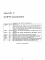
CLAP D parameters
64
58
58
List of Figures
2.1
2.2
2.3
2.4
The ISDN protocol reference model layers 1 to 3 (basic access).
Format of layer 2 frames.
Multiplexing of data links using SAPI and TEL. . . . . . . . .
Layer 2 primitives associated with the interaction between layer 3 and the
management entities. . . . . . . . . . . . . . . . . . . . . . . . . . . . . . . ..
2.5 State transition diagram of the data link connection endpoints (between layers
2 and 3).. . . . . . . . . . . . . . . . . . . . . . . . . . . . . .
2.6 State transition diagram of a data link in layer 2. . . . . . . .
2.7 Example of the procedure to establish a data link connection.
2.8 Control field parameters of an I-frame. . . . . . . . . . . .
2.9 Example of a procedure to release a data link connection.
9
10
11
3.1
3.2
3.3
3.4
3.5
3.6
3.7
3.8
The basic data link layer entities. . . . .
Schematic view of the operating system.
Declaration of the message structure. . .
Definition of a process descriptor. . . . .
SDL-representation of SABME response and corresponding C-code. .
Declaration of the state structure.
General structure of the dispatcher. . . . . . . . . . .
The basic data link layer entities shown as processes.
20
21
22
23
24
25
27
29
4.1
4.2
Block diagram of the ISDN Express Card. . .
Block diagram of the ISDN Terminal Board..
31
32
5.1
5.2
5.3
5.4
5.5
Functional block diagram of the Subscriber Network Interface Circuit (SNIC).
Receive packet algorithms using polling and interrupts. .
Transmit packet algorithm with the use of interrupts.
Outline of the interrupt handler.
Timer interrupt handler. . . . . . . . . . . . . . . . . .
34
38
40
41
42
6.1
6.2
6.3
6.4
6.5
6.6
Test configuration for testing transmission and reception of packets.
Test configuration for monitoring the functional behaviour of the protocol. .
Layout of the protocol analyzer. .
Test for data link layer release. . . . . . . . . .
Test for data link layer setup. . . . . . . . . . .
Test for data link layer information transport. .
45
47
48
48
49
49
4
12
13
15
16
17
18
List of Tables
2.1
Protocol mechanisms in LAP D.
14
5.1
5.2
HDLC Transceiver frame format.
Description of the SNIC registers ..
35
35
6.1
6.2
Duration of basic functions measured by ZTimer.
51
Response times ofthree consecutive data link layer setup procedures (estimation). 53
A.1 Description of the SNIC registers..
58
B.1
B.2
B.3
BA
B.5
B.6
B.7
B.8
61
61
62
62
62
63
63
63
Format of layer 2 frames. . . . . .
Command/Response bit definition.
SAPI definitions. . . . . .
TEl definitions. . . . . . .
Commands and responses.
Use of P /F bit
.
Management message structure..
Codes for messages concering TEl management procedures.
C.1 List of used LAP D parameters
.
5
64
Chapter 1
Introduction
Until the mid 1970s, telecommunication services were limited to voice and written communication. During the last 15 years or so, new demands on telecommunication services have
arisen, such as videotext, fax, communicating microcomputers, etc. To meet a variety of
needs by a large number of specialized networks has certain disadvantages for both the customer and the service providing companies. These disadvantages involve mainly high costs
and inefficiency [5].
As a result of advances in technology, digital techniques are being intensively introduced in
many countries. The result has been a general consensus in the world of telecommunication
to lay down through the International Telegraph and Telephone Consultative Committee
(CCITT) the basis elements of a universal network - the Integrated Services Digital Network
(ISDN):
"The main feature of the ISDN concept is the support of a wide range of voice and
nonvoice applications in the same network. A key element of service integration
for an ISDN is the provision of a range of services using a limited set of connection types and multi-purpose user-network interface arrangements." (Extract
from Recommendation 1.120.)
The ISDN is modelled according to the Open Systems Interconnection (OSI) concept. A
brief discussion of the ISDN-protocol reference model is given in [7].
The above citation speaks of a 'limited set of connection types' and 'multi-purpose usernetwork interfaces'. The ideal situation would be one device that on the one hand connects
to the network, and on the other hand provides a network access to a telephone, a fax, a
personal computer, etc. In practice however, this will certainly not be the case, due to the
diversity and enormous amount of interfaces the device should handle.
The Digital Systems Group ofthe Faculty of Electrical Engineering, Eindhoven University,
is conducting research involving the ISDN. As a part ofthis, an ISDN terminal board has been
designed. This board provides access to the ISDN and its services. The board is equipped
with a parallel interface for connection to e.g. a personal computer, a connection for a digital
phone and the so called S-interface (this is the point where the network is 'terminated';
roughly where the actual wire enters the customer premises). An Intel 80186 microprocessor
resides at the heart of the hardware. The terminal will be used as an experimental ISDN
terminal on which available and/or future services can be implemented and tested.
A dedicated operating system has been developed by Oudelaar [8]. It accommodates the
ISDN lower layer protocols extremely well. An important advantage of the operating system
6
CHAPTER 1. INTRODUCTION
7
is that the protocols can be implemented hardware independently. The only link to the
hardware are the low level interrupt handlers that communicate with the operating system.
To assist with the implementation of the ISDN protocols, the Digital Systems Group is in
the possession of two Mitel ISDN Express Cards. These make it possible to establish a 2B+D
connection (S-interface) between two personal computers (PC's). Using this connection and
the D-channel, layers 2 and 3 can be implemented and tested. When the implementation is
completed, the result can be copied onto the ISDN terminal board with only minor modifications.
Layer 3, the Network layer, has been implemented by Lemmens [7]. Layer 2, the Data
Link layer, was only partially functioning. In this report, it is described how the layer 2
implementation is completed, starting with the work of van de Kuilen [12].
Besides various errors in the software, the layer 2 software could not communicate properly
with layer 1. Low level drivers had to be added to make data transportation possible. A
question that arose during the project involved the performance of the implementation. What
restrictions or problems would arise as LAP D would perform at its maximum rate? Would
the operating system impose any restrictions as to the speed of the data transportation?
These questions will be answered in chapter 6, where the implementation performance is
examined.
The next chapter will give the reader a brief introduction to the ISDN user-network
interface and the ISDN layer 2 protocol in particular. Chapter 3 discusses the implementation
of the layer 2 protocol, independent of the hardware configuration. Chapter 3 does not require
the knowledge of the layer 2 protocol. Chapters 4 and 5 go into detail about the hardware
configuration that was used and the corresponding software. In order to fully understand
chapter 5, it is advisable to read chapter 4 first. Chapter 6 will then look at the real time
performance of the implementation. The conclusions are summarized in chapter 7, along with
a few words on future work.
Chapter 2
Link Access Procedure D
This chapter describes in detail the ISDN protocol for the Data Link layer, the Link Access Procedure on the D-channel (LAP D). Additional information can be found in CCrTT
recommendations Q.920 and Q.921 [9].
2.1
ISDN User-Network Interface
The ISDN user-network interface is located at the SIT reference point (illustrated in figure 2.1). Two access scenario's are currently defined on this point:
Basic access: An interface at a usable rate of 144 Kbit s-1. It supports two B-channels at
the rate of 64 Kbit S-1 and one D-channel at the rate of 16 Kbit s-1.
Primary rate access: An interface at a usable rate of either 1984 Kbit s-1 (Europe) or
1536 Kbit S-1 (USA & Japan). This interface supports 30 or 23 B-channels (64 Kbit s-1),
and one D-channel (64 Kbit s-1).
The B-channels are used for 64 Kbit S-1 data transport whereas the D-channel is used to
transport signalling information (16 Kbit s-1). From here on, basic access will be used
(2B+D).
As figure 2.1 shows, the characteristics of the physical layer is specified by CCITT recommendation 1.430. This layer performs multiplexing of the D- and B-channels, D-channel
contention resolution, synchronization, and activation/deactivation. The characteristics of
the D-channel of the data link layer are specified by CCITT recommendations Q.920/Q.921.
These are called the Link Access Procedures on the D-channel, or LAP D. The network layer's
characteristics are specified by CCITT recommendations Q.930-Q.940. On these two layers,
no B-channel restrictions are imposed. I will therefore restrict myself to the D-channel. Since
the network layer has already been implemented, I will furthermore concentrate on the data
link layer.
2.2
LAP D functions
The Link Access Procedures on the D-channel provide an error free data link connection
to convey information between layer 3 entities across the ISDN user-network interface using
8
CHAPTER 2. LINK ACCESS PROCEDURE D
9
LT
NT!
TE
ET
(network)
(user)
3
Network layer
2
Data link layer
Physical layer
Physical media
SiT
u
FIGURE 2.1: The ISDN protocol reference model layers 1 to 3 (basic access). NT2,
not shown, would be positioned between TE and NT1. It much resembles the TE.
the D-channel. This can be between the terminals and NT2, between NT2 and ET (network node or exchange termination), or between user terminals and the subscriber serving
exchange (NT1) (see figure 2.1). LAP D supports multiple terminal installations at the usernetwork interface and multiple layer 3 entities. To achieve this, LAP D performs the following
functions:
1. demarcation by means of flags, alignment and transparency of the transported frames;
2. the multiplexing of several data links on the same D-channel;
3. frame sequence maintenance in case of numbered frames;
4. detection of errors;
5. flow control.
LAP D is based on the High Level Data Link Control (HDLC) protocol. This protocol is
described in [4], together with the necessary changes.
2.3
LAP D frame format
All layer 2 peer-to-peer information is transmitted in frames conforming to the format in
figure 2.2. The format defines several fields, which are described below.
Opening & Closing Flag: Used to synchronise frames.
Address field: Consists of a Service Access Point Identifier (SAPI), a Terminal Endpoint
Identifier (TEl) and a Command/Response bit.
The SAPI indicates the type of service which can be signalling (SAPI=O) or packet data
(SAPI=16), whereas SAPI=63 is used for layer 2 management.
The TEl can take on any value in the range of 0.. 127. Value 127, the group TEl, is
assigned to the broadcast data link connection. Values 0-63 are selected by the user
10
CHAPTER 2. LINK ACCESS PROCEDURE D
0
0
Opening Flag
1
1 1 1 1
0
SAPI
I C/R 10
TEl
I1
Control Field
Information Field
Frame Check Sequence
Closing Flag
1 1 1 1 1
1
0
octet 1
1
octet 2
octet 3
octet 4(5)
octet 6
octets N-2, N-l
octet N
FIGURE 2.2: Format of layer 2 frames.
(non-automatic TEl assignment), values 64-126 are selected by the network (automatic
TEl assignment).
The user sends command frames with the C/R-bit set to '0' and response frames with
the C/R-bit set to '1'; the network does the opposite.
Control field: This field identifies the type of frame, which will be either a command or a
response frame. Three types of control field formats are defined:
1. numbered information transfer (I-format). Used to perform layer 3 information
transfers. Send and receive sequence numbers are included to enable acknowledgement.
2. supervisory format (S-format). Used for acknowledgements and requests for retransmission.
3. unnumbered information transfer and control functions (U-format). Used for data
link control functions.
All three formats include a P IF-bit. Its use is defined by the peer-to-peer procedures.
P stands for Poll, F stands fO£ Final, indicating if a response is required.
Information field: The contents of this field are determined by the control field. In an
information frame it will contain layer 3 information, and in e.g. a Frame Reject frame
it will contain more specific information about the rejection.
Frame check sequence: These 2 octets are added to detect possible transmission errors.
A full description of the frame format is located in appendix B.
The SAPI and the TEl together form the Data Link Connection Identifier (DLCI). The
DLCI identifies a LAP D data link connection. Figure 2.3 illustrates the identification of a
LAP D connection. As can be seen by this figure, one terminal can have more than one TEl
assigned to it (see TE2: it is assigned TEl values 3 and 8). A terminal is not identified by one
TEl; the TEl merely identifies a specific connection endpoint within a service access point.
In other words, within the signalling entity (a service access point), more than one data link
connection can be processed.
11
CHAPTER 2. LINK ACCESS PROCEDURE D
User
Network
Layerr-_ _------,
Network
TEl
TEZ
Network
Layerr-_ _-----,
ET
Network
Layer
,e===:Ii
Data
link
Layer
D-channel
SAPI=O
- - = Poinl-lo-poinl dala link connection
................ = Broadcasl data link connection
DLeI = SAP! + TEl
SAPI=16
q-d''''
H"' I.y~
.. "",
~I"
p""1
data link layer connection endpoint
FIGURE
2.4
2.3: Multiplexing of data links using SAPI and TEL
Modes of operation
The data link layer supports two modes of operation for layer 3 information transfer. Both
modes may exist on one D-channel at the same time.
Unacknowledged information transfer
This mode can also be named the connectionless mode. No error correction or flow control
is used to transfer U-frames. I-frames cannot be transferred in this mode. The mode can
be used for point-to-point communication between a user and the network or for multi-point
communication for the broadcast offrames to several terminals (e.g. TEl verify procedure).
Acknowledged information transfer
This mode is only possible when a data link connection has been established. A connection
is made using the Set Asynchronous Balanced Mode Extended (SABME) command. This is
an inheritance of HDLC.
12
CHAPTER 2. LINK ACCESS PROCEDURE D
VNFONAIAnON rJUNSJEN)
3
DL-DATA-INDICATlON
DL- UNIT-DATA -INDI CATION
DL-DATA-REQUEST
DL- UNIT-DATA- REQUEST
(LlArA £INK CONTNOl)
DL- RELEASE-CONFIRM
DL- ESTABLlSH-CONFIRM
DL- RELEASE- INDICATION
DL-ESTABLlSH - INDICATiON
DL-ESTABLISH-REQUEST
DL-RELEASE-REQUEST
2
MDL-REMOVE-REQUEST
MDL- ASSIGN -REQUEST
PH-DATA-INDICATION
MDL-UNIT-DATA-REQUEST
MDL-ERROR-REQUEST
MDL- UNIT- DATA-INDICATION
1
PH- DATA-REQUEST
Layer 2
Management
MDL-ASSIGN-INDICATION
MDL-ERROR-lNDICATION
FIGURE 2.4: Layer 2 primitives associated with the interaction between layer 3 and
the management entities.
2.5
Layer 2 interfaces
Layer 2 communicates with layers 1 and 3 as well as the management layer through messages
called service primitives. The messages to and from layer 1 concern layer 2 frames that are
transmitted and received. Layer 3 not only passes down its own information frames, but
also commands to layer 2. These commands control the data links. Communication with
management includes TEl-assignment and error report. Figure 2.4 shows the layer 2 interfaces and the possible primitives. Layer 1 communicates (lower left) with layer 2 through the
PH-DATA primitives. This concerns layer 2 frames that have been received or are to be transmitted. Layers 2 and 3 exchange similar primitives, now concerning layer 3 frames (upper
left). The second group of primitives exchanged between layers 2 and 3 concern the initiation
and termination of a data link (upper right). This leaves the primitives exchanged with layer
2 management. Here there are three types of primitives: those concerning management information frames (MDL-DATA), those concerning TEl assignment or removal (MDLREMOVE,
MDL-ASSIGN), and those concerning error handling (MDLERROR).
These primitives are conceptual and are not necessarily implemented. They provide the
procedural means to specify conceptually how a data link user can invoke a service. Through
the use of primitives a point-to-point data link layer connection endpoint can be triggered
from one state to the other.
A data link layer connection endpoint can be in one of four basic states, illustrated in
13
CHAPTER 2. LINK ACCESS PROCEDURE D
DL-RELEASE-CONF1RII
DATA UNK CONNECJ'lON
RELEASED
----
DL-RELEASE- REQUEST
DL-ESTABI.JSH-INDlCATlON
DL-DATA- REQUEST/INDlCATlON
FIGURE 2.5: State transition diagram of the data link connection endpoints (between
layers 2 and 3).
figure 2.5:
• link connection released state (stable state)j
In this state the data link is idle. It will be activated when layer 3 asks for a data link
establishment (DL-ESTABLISH-REQUEST) or when layer 2 indicates an established
data link (DL-ESTABLISHJNDICATION).
• awaiting establishment state (transition state);
A data link has signalled its peer to establish a data link. As soon as a positive acknowledgement is received (DL-ESTABLISH_CONFIRM), a data link is considered established.
• awaiting release state (transition state);
A data link is waiting for its peer to acknowledge the request to release the data link.
• link connection established state (stable state).
In this state information transfer is possible.
The illustration shows that primitives occur in all four basic states. In a normal situation,
however, a data link connection endpoint passes through the states counter-clockwise. Its
peer, only reacting to requests, merely switches between the link connection released and
established states. The next section discusses the data link connection procedures in more
detail.
CHAPTER 2. LINK ACCESS PROCEDURE D
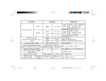
TABLE
2.1: Protocol mechanisms in LAP D.
Function:
connection establishment
connection release
addressing &
multiplexing
framing
flow control
error detection &
-correction
reset
2.6
14
Protocol Mechanism
SABME and UA frames
DISC and UA frames
TEl and SAPI
flags and zero insertion
sliding window and RNR-frames
FCS-test
sliding window
time-out
REJ-frames
P IF -checkpointing
SABME and UA frames
LAP D protocol mechanisms
This section will describe how data links are established, how information transfer happens
and what functions the management entity performs. Table 2.6 shows how the most important
protocol functions are realized in LAP D. These functions are discussed below. In the previous
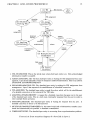
section, a state diagram of the data link connection endpoints was shown (figure 2.5). When
looked at from the layer 2 side, a more complex state diagram can be seen; see figure 2.6 on
the next page. Nonetheless, the four basic states can be seen: the top four (1-4) form the
link connection released state, the lower two (7-8) form the link connection established state.
The awaiting establishment and awaiting release states have similar names (5-6). A global
description of each state is included in figure 2.6.
15
CHAPTER 2. LINK ACCESS PROCEDURE D
(1) TEl
unassigned
TEl removal
TEl assignment
(3) Establish
awaiting TEl
Establish
request
(2) Assign
awaiting TEl
TEl
assignment
TEl
assignment
Establish
request
(5) Awaiting
establishment
release
complete
peer
initiated:
establishment
(6) Awaiting
release
release
establishment
complete
(7) Multiple Ifrarne
establis~ed
Timing
recovered
T200 timer
expiry
1. TELUNASSIGNED: This is the initial state a data link layer entity is in. Only acknowledged
information transfer is possible.
2. ASSIGN-AWAITING_TEI: The data link layer entity is waiting for TEl assignment from management. Layer 3 has indicated it wants to transport numbered information. This is an indirect
DATALINK -.ESTABLISH_REQUEST.
3. ESTABLISH-AWAITING_TEI: The datalink layer entity is waiting for TEl assignment from
management. Layer 3 has requested the establishment of a datal ink connection.
4. TEI-ASSIGNED: The datalink layer entity is ready for action, which will be the establishment
of a datalink connection or the removal of the TEl value.
5. AWAITING_ESTABLISHMENT: A request for a datalink connection has gone out to the peer
of the datalink layer entity. This is a wait state, waiting for response from the peer in order to
enter multiple frame operation.
6. AWAITING-.RELEASE: The datalink layer entity is waiting for response form its peer. A
datalink connection is about to be disconnected.
7. MULTIPLE-FRAME_ESTABLISHED: In this state both kinds of information transfer (numbered and unnumbered) are possible. A datalink is established.
8. TIMER_RECOVERY: The datalink layer entity is recovering from a synchronization problem.
FIGURE
2.6: State transition diagram of a data link in layer 2.
16
CHAPTER 2. LINK ACCESS PROCEDURE D
TEl Unassigned
01-ESTABLISH-REQUEST
M01 ASSIGN INDICATION
ID-REQUEST
~
~
ID-ASSIGNED
..
"-
~
-
~
-
-
~
- Establish Awaiting TEl
MD1-ASSIGN - REQUEST
(TEl)
"-
"?
f--
SABME CMD
Awaiting Establishment
UA RESP
""
01 ESTABLISH CONFIRM
....
~
Multiple Frame Established
L2 management
FIGURE
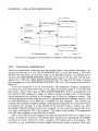
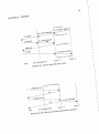
2.6.1
Layer 2
Layer 3
2.7: Example of the procedure to establish a data link connection.
Connection establishment
There are several states a data link must go through before it can transfer information. Assuming the data link is in the TELUNASSIGNED state, it must first obtain a TEl value.
Without this TEl value, the data link could not be identified properly. Considering layer 2
receives a DL-ESTABLISH-REQUEST primitive from layer 3, the data link will ask management for a TEl value (MDL...ASSIGN_INDICATION). The data link will await a response
from management in the ESTABLISH...AWAITING_TEI state. This process is illustrated in
figure 2.7.
If the user equipment is of the non-automatic TEl assignment category, management
can choose any unoccupied TEl value in the range of 0..63 and assign it to the data link
layer entity. This is done using an MDL...ASSIGN-REQUEST. If the user equipment is of
the automatic TEl assignment category, an Identity request message is sent to the network.
Several parameters are included in the message, one of which is a Reference number. This
randomly generated number helps the network to distinguish between different requests, since
no other identification of the data link is available (no TEl assigned!). The network can
respond with an Identity assigned message, confirming the assignment of a certain TEl, which
is included in the message. It is also possible for the network to deny a request, e.g. when
all available TEl information/resources are exhausted. In such a case the network will, on its
own, start verifying each TEl it has assigned. This might reveal multiple TEl assignments
(one TEl value assigned to more than one terminal).
After a TEl value has been assigned, the data link layer entity will try to make a connection. It initiates a request for the multiple frame operation by transmitting the SABME
command to its peer. If its peer is able to comply it will respond with a UA response. The
connection is now established and acknowledged information transfer is possible. Both data
CHAPTER 2. LINK ACCESS PROCEDURE D
17
link layer entities are in the MULTIPLE-FRAME-ESTABLISHED state. In case the peer
data link layer does not respond with a UA frame, a data link cannot be properly set up, and
appropriate action (as specified by LAP D) is taken.
2.6.2
Acknowledged information transfer
This section only applies to I-frames, because U-frames require no special treatment. I-frames,
however, are transmitted with several control field parameters. Through these parameters
flow control is realised. LAP D makes use of the sliding window protocol (go back n). The
parameters and the associated variables are listed below. Figure 2.8 shows how the control
field is made up.
Encoding of bits
1
2 3 4 5 6 7
N(S)
o I
N(R)
P/F I
8
FIGURE 2.8: Control field parameters of an I-frame.
N(S): Send sequence number; send sequence number of transmitted I-frames. It is included
in each transmitted I-frame.
V(S): Send state variable; the sequence number of the next I-frame to be transmitted
(V(A) ~ V(S) ~ V(A)+k).
V(A): Acknowledge state variable; identifies the last frame (V(A)-l) that has been acknowledged by its peer.
~ N(R) ~ V(S)); expected send sequence number of
next received I-frame. It is included in each transmitted I-frame.
N(R): Receive sequence number (V(A)
V(R): Receive state variable; denotes the sequence number of the next in-sequence I-frame
expected to be received.
k: determines the size of the sliding window. Sequence numbers are numbered modulo 128.
For information about the sliding window mechanism, see [11].
LAP D uses a window size of 1 in the case the data link is used for signalling. When
used for packet data, the window size is 3.
Information from layer 3 in a DLDATA.REQUEST primitive is transmitted in a layer 2 1frame. An I-frame can be transmitted only when VS ~ V(A)+k, Le. when less than k frames
are outstanding. On transmission of an I-frame, the control field parameters N(S) and N(R)
are assigned the values of V(S) and V(R), respectively.
On reception of an I-frame with N(S) equal to the current V(R), the information field of the
received frame is passed to layer 3 using the DLDATAJNDICATION primitive. Furthermore,
V(R) is incremented by one. The I-frame is acknowledged with another I-frame or Supervisory
frame with N(R) set to V(R).
Acknowledgement occurs upon reception of a valid I-frame or Supervisory frame. The
acknowledging entity included N(R) in the control field of the response frame, saying it next
18
CHAPTER 2. LINK ACCESS PROCEDURE D
Multiple Frome Established
\
D1-RELEASE-REQUEST
~
....
DISC CMD
-
Awaiting Release-
-
UA RESP
D1 RELEASE CONFlRM
TEl Assigned-
L2 management
FIGURE
Layer 2
Layer 3
2.9: Example of a procedure to release a data link connection.
expects a frame with sequence number N(R). The peer entity treats N(R) as the acknowledgement for all the I-frames that have been transmitted with a send sequence number N(S)
up to and including the received N(R)-l. The acknowledge state variable is set to N(R).
Sequence errors
N(S) sequence error In this case the receiver did not receive the frame it expected:
N(S) =I VCR). The information field in the frame is discarded, and no acknowledgement takes
place. If the frame is otherwise error-free, N(R) is used as acknowledgement as explained
above. A REject frame is transmitted to initiate recovery of the correct frame sequence.
The side that receives the REJ frame will use the N(R) in the REJ frame as the next send
sequence number. YeA) is also set to N(R), which indicates the last frame that was received
correct. The requested frame (N(R)) is then retransmitted as soon as possible, as well as any
other frames with a sequence number greater than N(R) (go back n principle).
N(R) sequence error This error occurs when N(R) is not in the range of [V(A)... YeS)].
If N(R) < YeA), a frame is acknowledged for the second time. If N(R) > YeS) a frame is
acknowledged that never has been sent. The information field of the received frame, if in
sequence, is passed on to layer 3. An N(R) sequence error causes the data link layer entity
to initiate re-establishment of the data link.
2.6.3
Connection release
A connection is released in much the same way as it is established (see figure 2.9). Instead
of a SABME command a DISConnect command is used. The data link will wait in the
AWAITING-RELEASE state until a UA frame is received. After release, the data link layer
entity is in the TEI-ASSIGNED state.
CHAPTER 2. LINK ACCESS PROCEDURE D
2.6.4
19
Timing restrictions
Every transmitted command (SABME, DISC, UA, I-frame, etc.) must be answered within
T200 seconds (a LAP D parameter). If no response is received in time, the command (except
the I-frame) is retransmitted. Retransmission may occur up to N200 times. If, after N200
retransmissions, still no response is received, a connection error is assumed. Depending on several variables, a data link may try to re-establish itself, or will return to the TELASSIGNED
state.
2.6.5
Errors
There is a number of errors that may occur during data transportation. Those errors that
cannot be resolved by the data link layer entity itself are passed to the layer management for
processing. In Recommendation Q.921 only a handful of error responses is listed; most other
responses are left for the designer to design and implement.
Summary
In this chapter, the ISDN layer 2 protocol, LAP D, on the user-network interface was described. The peer-to-peer frame format has been shown, as well as the interaction between
layers 1 and 3, and layer 2 management. After discussing the four basic states of a data link
connection endpoint, a detailed view of the behaviour of a data link connection itself was
given. Three elements were discussed in particular: connection establishment, information
transfer and connection release.
The next step towards implementing LAP D is creating the appropriate data structures
to accommodate the state machine behaviour of LAP D. The following chapter will elaborate
on this.
Chapter 3
LAP D implementation
As could be seen in the previous chapter, LAP D is specified as a state machine. Each
data link layer entity is always in a defined state. The entities communicate with adjacent
layers by primitives. We can regard the different data link layer entities as processes that
communicate by messages. This yields the schematic of figure 3.1. The lines between the
entities (or processes) indicate communication (messages).
LM
1
FIGURE
3.1: The basic data link layer entities.
To accommodate the LAP D protocol on the ISDN terminal board, an operating system
supporting the above approach has been created by Oudelaar [8]. It was developed keeping
in mind the following considerations:
• it should provide support for a large number of processes (entities). This enables us to
implement layer 3 in the same way (this has been done by [7]).
• it should allow a priority mechanism for the processes Layer 2 processes have stricter
timing constraints than layer 3 processes, and thus sometimes need priority treatment.
• it should allow a small number of hardware interrupts. The interrupt handlers of those
interrupts must be fast in order not to stall any process.
20
21
CHAPTER 3. LAP D IMPLEMENTATION
DispatcheJ
Hardware
FIGURE 3.2: Schematic view of the operating system.
Figure 3.2 gives a schematic view of what is from now on called the Oudelaar operating
system. As it turned out, a very interesting property of the operating system was that it is
hardware independent. It allows implementation and testing on different systems. In my case
this means I can use ISDN hardware that is operational ("known good") to test the approach
of this chapter. When it is finished, it will be transported to the ISDN terminal board.
3.1
Messages
All action is based on the exchange of messages. They can be generated by a certain process
to pass on information to another process. In LAP D for example, the information may be
service primitives like DLRELEASE-REQUEST. Each message unit must at least contain information about the type of message and the destination ofthe message. Figure 3.3 shows the
data structure ofthe messages (implementation is in C language). The nucleo field holds the
message type (this can be DLESTABLISH_REQUEST, SABME, etc.). The dest and orig
fields hold the destination and originating processes' identities, respectively. The five parameter fields constitute the information field of the message. A DLESTABLISH-REQUEST
primitive has no information fields, whereas a DLUNIT _DATAJNDICATION contains a
layer 3 frame. Figure 3.3 shows what information is usually stored in the five parameters.
Messages are collected in a FIFO (First In First Out) queue. This is done in the form
of a pointer to a buffer, which holds the actual message. The message queue is entirely
controlled by the dispatcher. A process can only put messages in the queue, not remove them
(there is one exception that will be explained in chapter 6). In order to favour the retrieval
of a certain message over others, several message queues are used. Each queue resembles a
priority. Priorities can range from 0 (highest priority) to MAXPRIO (lowest priority). The value
of MAXPRIO is for this time unrelevant, but will be given in chapter 6.
CHAPTER 3. LAP D IMPLEMENTATION
22
struct message
{
'llord nucleo;
byte dest;
byte orig;
union scratch
union scratch
union scratch
union scratch
union scratch
param_1;
param...2;
param..3;
paramA;
param....5;
1*
1*
1*
1*
1*
1*
1*
1*
1*
Holds the message type *1
Destination process *1
Originating process *1
Received H(5) *1
Received H(R) *1
Received P/F *1
Received C/R *1
Pointer to buffer of *1
information field *1
}
FIGURE
3.3: Declaration of the message structure.
The queues are accessed by three functions. These are described in below.
void message (word Mes. byte Dest. byte Orig. byte Pari, byte Par2
byte Par3. byte Par4. byte Par5) { ... }
This function is called by the various processes to place a message in the message queue
indicated by the priority of the Destination process.
Mes: message
Dest: destination process
Orig: originating process
Prio: priority of message
Pari: information
byte getmsg (byte Prio) { ... }
This function checks the queue for messages and returns the message that is in the front
of the queue. Prio indicates which queue should be checked. getmsg returns a byte
pointing to a message buffer holding the actual message elements. The message is not
removed from the queue, it is just read. This is done in order to prevent the buffer to
be replaced by a new message, destroying the current contents.
void updatequeue (byte Prio) { ... }
This function is called by the dispatcher after a message has been processed. At that
time the information in the message buffer is used and the buffer no longer needed.
updatequeue does the required removal by updating the queue pointers, where Prio
indicates which queue is to be updated.
3.2
Processes
The messages described in the previous section, activate the various processes. These processes, each representing a data link layer entity, all have an associated process descriptor.
This descriptor holds vital information about the process, and is saved each time a process
is deactivated. All process descriptors are held in an array, where the indexes identify the
processes. This is illustrated in figure 3.4.
23
CHAPTER 3. LAP D IMPLEMENTATION
define unsigned char byte;
define MAXPRIO #
define MAXPROC #
/* maximum priorities of process:
/* number of defined processes */
[O .. MAXPRIO] */
union scratch
{
unsigned char byte;
unsigned int vord;
unsigned char *pbyte;
unsigned int *pvord;
}
struct process
{
byte
byte
struct state far
byte
union scratch
union scratch
union scratch
union scratch
union scratch
union scratch
union scratch
union scratch
}
PublStat;
Priorid;
*State;
Substate;
Data1 ;
Data2;
Data3;
Data4;
Data5;
Data6;
Data7;
Data8;
/* Status (Blocked or Running) */
/* Priority */
/* Extra for LAP D processes */
/* Parameters */
struct process Process[MAXPROC]
FIGURE 3.4: Definition of a process descriptor.
Each descriptor consists of twelve elements. First of all, the PublStat field holds the
status of the process. It is either Blocked or Running. A Blocked process cannot receive
messages, until it becomes Running. Once a process is Blocked, it can only be unBlocked by
another (unBlocked) process. If, for example, no packet data is supported, layer management
may block the packet data entity process. The Priorid field holds the process's priority. All
messages for a certain process are placed in the queue with the corresponding priority value.
The State field provides information about the current state the process is in. It points to
the state table that should be used if a message is received. Some processes need to register
several important conditions (Own Receiver Busy, Peer Receiver Busy). These are saved in
the Substate field. Datal - Data8 are storage space for variables unique to a process. These
can be send and receive state variables, a retransmission counter, etc. As an example, I have
included the declaration of the signalling entity for the B-channel:
Process[LAPD..s 1J.PublStat
Process [LAPD..s 1J.Priorid
= RUNNING;
= 1;
24
CHAPTER 3. LAP D IMPLEMENTATION
void far sabme-4(void)
{
if (ABLE_TO-ESTABLISH)
{
tx(UA. p. 1);
1* F=P • response *1
message (DL-ESTABLISH...INDICATIOI. LAYER3.
ProcAct. O. O. O. o. 0);
VS = 0;
VA = 0;
VR = 0;
stoptmr(T200_TIMEJDUT. ProcAct);
runt imer (T203_TIMEJDUT. ProcAct. T203);
SUBSTATE = 0;
1* clear exceptions *1
IEWSTATE = MULTIPLEJrRAME-ESTABLISHED;
}
else
{
tx(DM. p. 1);
1* F=P • response *1
}
}
FIGURE 3.5: SDL-representation of SABME response (left) and corresponding Ccode (right).
Process[LAPD..51].State
Process[LAPD..51].Substate
Process[LAPD..51].Datal.byte
Process[LAPD..51].Data2.byte
Process[LAPD..51].Data3.byte
Process[LAPD..51].Data4.byte
Process[LAPD..51].DataS.byte
Process[LAPD..51].Data6.byte
Process[LAPD..51].Data7.byte
Process[LAPD..51].DataB.byte
= TELUNASSIGNED;
= OJ
/* SAPI */
= OJ
= 200j
= OJ
= OJ
= OJ
= OJ
= OJ
= OJ
/* TEl, 200 = not assigned */
/* VS Send state variable */
/* VA Acknowledge variable */
/* VR Receive state variable */
/* RC Retransmission counter */
/* Able to establish flag */
/* Acknowledge pending flag */
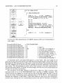
As mentioned above, the State field points to a state table. The state tables for all
processes involved were derived from the CCITT Recommendation Q.921, Annex B [9]. Annex
B provides the SDL representation ofthe point to point procedures ofthe data link layer entity.
The SDL diagrams do not describe all of the possible actions and conditions of the data link
layer entity. The shortcomings are minor and of little concern to the basic performance of
the data link layer entities. It should be noted though, that the text of the recommendation
prevails over any SDL inconsistency.
The translation of the SDL diagrams is illustrated in figure 3.2. Here I assume a data
link layer entity to be in the TELASSIGNED state, receiving a SABME command. The
relation between the diagram on the left and the code on the right speaks for itself. I will not
go into the detail of discussing precise implementation of VS, VA, HR, etc. All implemented
functions are collected in state tables. These state tables are made up of rows containing a
possible input message and the corresponding function that must be executed on receipt of
CHAPTER 3. LAP D IMPLEMENTATION
25
struct state
{
word nucleo;
void (*transi)(void)
1* The incoming message *1
1* The function to be executed (transi) *1
};
void dummy(void)
{
}
1* Empty function *1
1* Does nothing *1
Each state defines a state table, which is an array of the above structure:
state StateTable[ ]=
{
{message-a, function-a},
{message..b, function..b},
{message_c, function_c}.
{DEF, dummy}
};
FIG U RE 3.6: Declaration of the state structure.
the message.
Figure 3.6 shows the necessary declarations. The state table of a data link layer entity in
the TEI-ASSIGNED state would look as follows:
state TEI...ASSIGNED [ ] =
{
{ DLJESTABLISHJREQUEST, dlestreq_4 },
{ DLJRELEASEJREQUEST, dlrelreq_4 },
{ DLUNIT...DATAJREQUEST, dlunitdatareq_4 },
{ UI...FRAME-IN_QUEUE, uiframe_4 },
{ MDLJREMOVEJREQUEST, mdlerrresp-2 },
{ SABME, sabme_4 },
{ DISC, disc_4 },
{ DEF, dummy}
};
Every state table must terminate with the entry {DEF, dummy} . This entry will guard the
process against messages that are not allowed in the current state by executing a dummy
(empty) function should such a message occur (see figure 3.6).
Besides the three data link layer entities, several other processes were created. They are
summed up below:
1. LAPD_Sl
2. LAPD_S2
CHAPTER 3. LAP D IMPLEMENTATION
26
3. LAPDJ>
4. MANAGEMENT
5. TRANSMISSION
6. MONITOR
7. layer 3 processes
The LAPD processes are implemented using the SDL diagrams. The MANAGEMENT process is derived from the text of Q.921. It is constantly in one state. Through this process, TEl
assignment and removal are realized, as well as the other functions of the layer 2 management
entity described in the previous chapter. The TRANSMISSION process is the link to the
hardware. Besides frame assembly and disassembly, the process initiates the transmitter on
the SjT-interface and can receive frames from the receiver on the SjT-interface. This process
is discussed in detail in chapter 5. The MONITOR process can be used to monitor the status
of the data links. It was originally introduced by Oudelaar ([8]) to be used on the ISDN
terminal board. I have not used this process. To monitor the data links I made use of the
protocol analyzer written by Lemmens ([7]). The analyzer is discussed in a later chapter.
3.3
The dispatcher
In figure 3.2, where a schematic view of the operating system is shown, the dispatcher
can be seen to control the message queue. The dispatcher is always active. Its structure is
shown in figure 3.7. It checks the message queues for messages, starting with the highest
priority queue. Once the dispatcher finds a message in one of the queues, the destination
process and current state of that process will automatically have been determined by getmsg.
If the destination process is running (not Blocked), the corresponding state table is searched
for the message's nucleo. The function that is found is executed. When no entry for the
nucleo is found, a dummy (empty) function is executed. Next, the message queue is updated
and the priority is set to 0, to start the next scan for messages with the highest priority. If
the destination process is Blocked, the message is discarded by updating the queue. This
procedure will then repeat itself.
The dispatcher can be integrated into a larger structure, as has been done in the case
of the protocol analyzer. Each message that is read by the dispatcher, is displayed on the
screen, providing information on the status of the data links. An important condition is that
the dispatcher's body is executed sufficient times to guarantee continuation of the various
processes controlled by the dispatcher.
27
CHAPTER 3. LAP D IMPLEMENTATION
dispatcherO
{
byte Pri;
word AuxComp;
struct state far *TablState;
= 0;
Pri
/* High priority */
while(1)
{
if(getmsg(Pri)
==
Present) /* message present?
*/
{
if(destination-process != Blocked)
{
look_up..nucleo...in...state_table () ;
(*(TablState->transi»();
/* execute function */
updatequeue(Pri);
/* discard message */
Pri = 0;
}
else /* destination-process blocked */
{
updatequeue(Pri);
/* discard message */
}
}
else /* no message present */
{
Pri
= ++Pri
r. MAXPRIO;
/* increment priority */
}
} /* endless while-loop */
}
FIGURE
3.7: General structure of the dispatcher.
CHAPTER 3. LAP D IMPLEMENTATION
3.4
28
Interrupts
For layer 2 to communicate with its peer, it must transmit and receive frames over the S/Tinterface. The link with the transmitter and receiver hardware is laid through interrupt
handlers that control the hardware. These interrupt handlers are different for each hardware
configuration the ISDN software is installed on. What can be the sources of the interrupts?
I will name a few.
• the receiver has detected a flag on the D-channel indicating the start of a packet.
• the receiver has been receiving a packet and has now filled its (relatively) small buffer.
• the receiver has detected an end-of-packet flag.
• the transmit buffer is running empty.
• the transmitter is signalling it has transmitted a complete packet.
The interrupt handlers servicing one of the above requests generate, if necessary, messages
for the TRANSMITTER process. This process is described further in chapter 5.
An entirely different type oflow level software concerns timers. Timers are necessary in the
LAP D communication process, as explained in section 2.6.4. In the current implementation,
each timer tick generates an interrupt, after which the active timers are updated. An expiring
timer generates a TIME_OUT message for the process that initiated the timer.
29
CHAPTER 3. LAP D IMPLEMENTATION
Summary
An overview of the LAP D implementation was given. It is best illustrated by figure 3.8. An
operating system was created by Oudelaar [8] to accommodate the LAP D state machine. It
regards data link layer entities as processes communicating by messages. We have also seen
that a dedicated dispatcher is in control. The behaviour of the data link layer entities was
translated from SDL diagrams into state tables. The link with the hardware elements was
shown to involve interrupts and interrupt handlers.
The behaviour of LAP D is fully documented by the CCITT. In order to discuss the
behaviour, and, more important, the implementation of the lower level handlers, we must
first explore the associated hardware. This is done in the next chapter, after which the
implementation of the lower level handlers can be discussed.
network layer
data link layer
layer
management
3.8: The basic data link layer entities shown as processes (the circles). The
service primitives are exchanged as messages via the message queues. The dispatcher
keeps track of the queues and delivers the messages to the processes.
FIGURE
Chapter 4
Hardware aspects
The software described in this report will eventually be implemented on the ISDN Terminal
Board developed in the Digital Systems Group. The software is first tested on the Mitel ISDN
Express Card. This chapter will describe the two systems.
4.1
ISDN Express Card Kit
The ISDN Express Card Kit with ISDN Evaluation System (IES) software is an integrated
hardware/software package, giving easy access to several ISDN reference points. The hardware
can handle low level protocol functions, while the software can control all of the components
on the card.
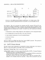
4.1.1
Hardware overview and block diagram
The hardware includes components for the basic access reference points (S & U), primary rate
reference points (T1 and CEPT), a digital telephone set component with speakerphone capability, and devices for digital switching, clock generation and synchronization and low-level
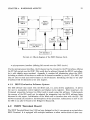
protocol functions. Figure 4.1 shows a block diagram of the card. The Digital Crosspoint
switch in the middle can interconnect any of its ports, allowing for several different configurations. In this case, a connection between the S-interface and the Digital Phone will be
used (see the user manual [13] on how to make such a connection). The connection is illustrated by a dashed line. The clock generator and DPLL provide necessary timing signals to
synchronise all the hardware and (optionally) the interfaces on the various reference points.
All four reference points on this card are connected to specialized circuits that perform layer
1 and part of layer 2 functions.
The most important device in relation to LAP D is the device connected the S-interface,
namely the Subscriber Network Interface Circuit (SNIC). It is a device that implements the
CCITT 1.430 Recommendation for the ISDN Sand T reference points. The SNIC may be
used at either side of the subscriber line (NT or TE). Some of its features are:
• point-to-point, point-to-multipoint and star configurations
• full duplex 2B+D
• on chip HDLC D-channel protocoller (LAP D is a subset of HDLC, see section 2.2)
30
31
CHAPTER 4. HARDWARE ASPECTS
CEPT
Trunk
,......
~
........
2048Kbit/s
30B+D
~
........
DNIC
U-interface
192Kbit/s
2B+D
..
.,.......
,......
~
......
Digital
Crosspoint
Switch
................... . __ ... "-- .......
T1
Trunk
1544Kbit/s
23B+D
~
.__ .... .............
,......
.....................
JL
S-interface
(SNIC)
192Kbit/s
2B+D
'V
IController
HDLC
IController
'tDLC
Ij l
~
Digital
Phone
.....
•
FIGURE
I Clock
Generator
and DPLL
I
~~
~~
I~CInter!ace
4.1: Block diagram of the ISDN Express Card.
• microprocessor interface (offering full control over the SNIC circuit)
Via the microprocessor interface, the D-channel can be rerouted to the PC-Interface, offering
the PC full control over the SNIC. This could also be achieved through the HDLC controllers,
be it with slightly more overhead. Appendix A contains full information about the SNIC,
including a number of functions to make the D-channel accessible by the PC. The SNIC can
then be used to send and receive frames on the D-channel. Interfacing the chip to the LAP
D software will be discussed in the next chapter.
4.1.2
ISDN Evaluation Software System
The IES software that comes with the Mitel card, is a menu driven application. It allows
the user to manipulate control registers and display status registers. More important, the
D-channel connection between two Mitel cards is made using this software. Unfortunately
the sources of the IES could not be adapted for integration into the ISDN software being
discussed in this report. Initialization of the Mitel card is therefore done with the IES. The
software manual [13] includes a full description of this procedure. Information on how to use
the IES is can also be found in the Designer's Manual [6].
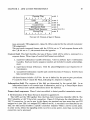
4.2
ISDN Terminal Board
The ISDN Terminal Board (see [14]) has been designed so that it can operate as a stand-alone
ISDN Terminal. It is equipped with multiple interfaces to allow various kinds of data com-
32
CHAPTER 4. HARDWARE ASPECTS
D
lor->
11111111111111111111111111111111111111111
/ /li =
=
ISDN terminal board
~ -1
I
Parallel interface
m!!m\
Ram
Processor
&
80186/82258
Rom
I
ISerial interface
..................
IDPC
I
IDPC
I
I
I
DSC
~ - S /T
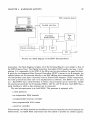
FIGURE 4.2: Block diagram of the ISDN Terminal Board.
munication. The block diagram in figure 4.2 of the Terminal Board is very similar to that of
the ISDN Express Card. The Digital Subscriber Controller (DSC) handles the layer 1 multiplexing. It is comparable to the SNIC of the Mitel card as they perform the same functions.
It gives the two Integrated Data Protocol Controllers (IDPC's) access to the B-channels. An
optional phone can be connected directly to the DSC offering voice communication. The DSC
can also perform some layer 2 functions such as Frame Check Sequence (FCS) computation.
All other protocol functions have to be implemented in software. The IDPC's can be used
to ). Each IDPC has a serial interface to which a data terminal can be connected. handle
bit-oriented protocols for the B-channels (HDLC, LAP D, LAP B (X.25)). Each IDPC has a
serial interface to which a data terminal can be connected.
The used microprocessor is an Intel 80186. This processor is equipped with:
- a clock generator
- two independent DMA channels
- a programmable interrupt controller
- three programmable 16-bit timers
- a local bus controller
Unfortunately, two DMA channels are insufficient as four are required (the two B-channels are
bidirectional). An 82258 DMA Coprocessor has been added to provide the needed capacity.
CHAPTER 4. HARDWARE ASPECTS
33
The terminal board is equipped with 512K Ram. This fairly large amount was chosen with
future expansion of the board's functions, as the board will be used to develop (new) ISDN
services. For more detail on the board's hardware, I recommend the reading of the graduation
report of Beijnsberger [2].
Comparing the Mitel card and the ISDN terminal board, we can see that the last could
be a part of the first. It would roughly replace the SNIC circuit with the DSC and the two
HDLC controllers with the two IDPC's (which actually are two HDLC controllers). The PC
interface indicated in figure 4.1 would be located at the parallel (and/or serial) interface of
the terminal board.
Summary
A brief description of the Mitel ISDN card and the ISDN terminal board were given. On the
Mitel card, the SNIC chip was pointed out as the relevant circuit for LAP D. Its equivalent
on the terminal board is the DSC. Both ISDN systems are accessible through a PC interface.
LAP D software is developed on the Mitel card, and will be transported to the terminal board
upon completion. The link between the Mitel card and the LAP D software will be explained
in the next chapter.
Chapter 5
Implementation of low level drivers
This chapter discusses the implementation of the low level interrupt handlers in reference to
the operating system in figure 3.2. These interrupt handlers together form the TRANSMISSION process, which is the link to the Mitel card hardware. The TRANSMISSION process
can access the SNIC circuit and so control the D-channel access.
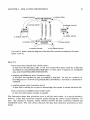
5.1
SNIC access
Figure 5.1 shows the functional block diagram of the SNIC. The microprocessor interface
allows complete control of the HDLC transceiver and access to all data, control and status
registers. The HDLC transceiver handles the bit oriented protocol structure and formats
the D-channel as per level 2 of the X.25 packet switching protocol defined by CCITT. It
transmits and receives the packetized data (information of control) serially in a format shown
in table 5.1. The data field refers to the Address (SAPI+TEI), Control and Information fields
D-channel priority
mechanism
~_ _~
OSTi
STBUS
interface
OSTo
foooolI_-----=F---_P""""-...
~
LTx
S-Bus
link
interface
Vbias
LRx
rood ....,'-------j
C4b....,'------'~
Timing
-.c:~~
and
control
rOb
STAR/RslO -.c:~~
. .-
Link
activation
controller
.....
~
VSS
NTITE -'------'~ '__.__.._____.---'
JrsTI
Cmode HALF
VDD
ADO-7
R/w/iffi
DS/RD
DinB
ArT/PRI
AS/ALE
PSC
~
OCR
FIGURE 5.1: Functional block diagram of the Subscriber Network Interface Circuit
(SNIC).
34
CHAPTER 5. IMPLEMENTATION OF LOW LEVEL DRIVERS
35
TABLE 5.1: HDLC Transceiver frame format.
FLAG
one
byte
DATA FIELD
n bytes
(n > 2)
FCS
two
bytes
FLAG
one
byte
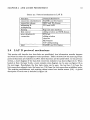
TABLE 5.2: Description of the SNIC registers.
A
S
y
N
C
S
y
N
C
Address
OxbOO
OxbOI
Oxb02
Oxb03
Oxb04
Oxb05
Oxb06
Oxb07
Oxb08
Oxb09
OxbOa
OxbOb
OxbOc
OxbOd
OxbOe
OxbOf
Write
Master Control Register
ST-BUS Control Register
HDLC Control Register 1
HDLC Control Register 2
HDLC Interrupt Mask Register
HDLC Tx FIFO
HDLC Address Byte #1 Register
HDLC Address Byte #2 Register
C-channel register
DSTo C-channel
S-Bus Tx D-channel
DSTo D-channel
S-bus Tx Bl-channel
DSTo BI-channel
S-Bus Tx B2-channel
DSTo B2-channel
Read
verify
verify
verify
HDLC Status Register
HDLC Interrupt Status Register
HDLC Rx FIFO
verify
verify
DSTi C-channel
C-channel Status Register
DSTi D-channel
S-Bus Rx D-channel
DSTi BI-channel
S-Bus Rx Bl-channel
DSTi B2-channel
S-bus Rx B2-channel
illustrated in figure 2.2. A valid frame should have a data field of at least 16 bits.
The HDLC transceiver is controlled through several registers. They are listed in table 5.2.
For more information, see [6} or appendix A. Most of the asynchronous registers (ASYNC)
are relevant to data communication on the D-channel. First there is the HDLC Control
Register 1. This is a write-only (read to verify) register. It can be used to enable/disable
the transmitter as well as the receiver. It is also used to direct the D-channel to the HDLC
transceiver, as the D-channel is normally routed to the STBUS interface (see figure 5.1). The
HDLC Control Register 2 is used to tag bytes that are written into the transmit FIFO. Bytes
can be tagged as end-of-packet (eop) indicating it is the last byte of the packet, or as frameabort (fa), indicating the packet should be aborted after the byte. This register reads back
the HDLC Status Register. It reports the condition of the transmitter and receiver FIFO's
(full, empty) and the status of the packet being received (top of receive FIFO is first byte of
packet, last byte of packet, packet is good or bad). The transmitter and receiver FIFO's are
accessible through their corresponding registers: HDLC Tx FIFO and HDLC Rx FIFO. The
HDLC Interrupt Mask Register is used to (un)mask interrupts generated by the transceiver.
Reading the HDLC Interrupt Status Register shows which interrupts occurred (interrupts are
reset after this action).
The above registers are the most important in relation to the transmission and reception
CHAPTER 5. IMPLEMENTATION OF LOW LEVEL DRIVERS
36
of bytes on the D-channel. The Data Book includes algorithms to accomplish this. I have used
these algorithms as a basis from which I developed a more advanced method. Before describing
this method, I shall first introduce the interrupts generated by the HDLC transceiver. I will
then describe the method to receive packets and transmit packets, respectively.
5.2
HDLC transceiver interrupts
The SNIC chip on the ISDN Express Card is able to generate eight maskable interrupts.
These occur upon a certain condition in the HDLC transceiver. These interrupts are:
GA
Indicates that a go-ahead sequence has been detected on the received HDLC
D-channel. I will not use it.
EOPD End of Packet Detected. Indicates that an end of packet has been detected on
the HDLC receiver. The packet can either be a good packet, an invalid packet
or an aborted packet.
TEOP Transmit End of Packet. According to the Data Book, this indicates that
the receiver has finished sending the closing flag of the last packet in the
Tx FIFO. Note: If the transmitter is disabled immediately after the TEOP
interrupt occurs, the receiving party will receive an aborted packet. Clearly
the TEOP interrupt occurs sometime before the transmitter sends the closing
flag. Advise: do not disable the transmitter after a TEOP.
FA
Frame Abort. Indicates that the receiver has detected a frame abort sequence
on the received data stream.
TxFL
Transmit FIFO Low. Indicates that the device has only 4 bytes remaining
in the Tx FIFO. This bit has significance only when the Tx FIFO is being
depleted and not when it is getting loaded.
TxFun Transmit FIFO Underrun. Indicates that the Tx FIFO is empty without
being given the 'end of packet' indication. The HDLC will transmit an abort
sequence after encountering an underrun condition.
RxFF
Receive FIFO Full. Indicates that the HDLC controller has accumulated at
least 15 bytes in the Rx FIFO.
RxFov Receive FIFO Overflow. Indicates that the Rx FIFO has overflown (Le. an
attempt to write to a full Rx FIFO). The HDLC will always disable the receiver
once the receive overflow has been detected. The receiver will be re-enabled
upon detection of the next flag.
In order to make use of the interrupt mechanism of the SNIC-chip, several registers must be
initiated correctly:
on the Mitel card:
• HLDC Interrupt Mask register: interrupts should be unmasked
• Master Control register: enable IRQ /NDA pin for HDLC interrupts.
on the PC:
• Interrupt Mask register of 8259 programmable interrupt controller: unmask hardware interrupt number 7 (IR7)
• Redirect software interrupt number 15 (which is generated upon IR7) to the SNIC
interrupt service routine.
CHAPTER 5. IMPLEMENTATION OF LOW LEVEL DRIVERS
37
These actions are implemented in the function inithardv.
An interesting but annoying problem occurred trying to program the Master Control
register: bit B2 should be set to "0" according to the data book to enable the NDAj I RQ pin
for HDLC interrupts. However, tests on the PC revealed that no interrupt 15 would occur
when an EOPD interrupt occurred on the Mitel card. A logic analyzer was therefore applied,
which showed a 125/1s clock signal. This is what the data book describes as the New Data
Available (NDA) signal, which should only appear on the NDAjIRQ pin when bit B2 is set
to "1". My suspicions were then confirmed: the programming of bit B2 should be exactly
opposite: a "1" for interrupt functioning, a "0" for NDA functioning.
5.3
Receiving packets
When the HDLC receiver is enabled, it can receive incoming packets. An incoming packet is
examined on a bit-by-bit basis, the FCS is calculated and the data bytes are written into the
19 byte receive FIFO. However, the FCS and other control characters i.e. flag and abort, are
never stored in the receive FIFO. All the bytes written to the receive FIFO are flagged with
two status bits. The status bits are found in the HDLC status register and indicate wether
the byte to be read from the FIFO is the first byte of the packet, the middle of the packet,
the last byte of the packet with good FCS or the last byte of the packet with bad FCS. This
status indication is valid for the byte that is to read from the receive FIFO. The incoming
data is always written to the FIFO in a byte-wide manner. Receive overflow occurs when the
receive section attempts to load a byte to a full receive FIFO. All attempts to write to the
full FIFO will be ignored until the receive FIFO is read. When overflow occurs, the rest of
the present packet is ignored as the receiver will be disabled until the reception of the next
opening flag.
It is now possible to design an algorithm to receive packets through the microprocessor
interface. The algorithm offered by the data book is shown in figure 5.2 (left). The upper
dashed box shows the loop where the software waits for the beginning of a packet. If a byte
is received (the Rx FIFO will not be empty) it is checked if it is indeed the first byte of a
packet. If it is, the next byte is read. If it is the last byte, the packet is tested on its FCS. If
it isn't the last byte, more bytes will be read when the Rx FIFO is not empty. Should, during
this receiving process, the Rx FIFO run empty, a waiting loop is entered (lower dashed box).
Please note that "first byte", "last byte" and "good FCS" conditions apply to the byte that
is in front in the FIFO. This explains the extra "read RxFIFO" in figure 5.2 (right) after the
"good FCS" test.
The dashed boxes show where the algorithm uses the polling technique to wait for a Rx
FIFO not empty situation. This is very time consuming. I have chosen to use the generated
interrupts to skip the waiting parts of the algorithm. Four of the interrupts are used. The
RxFF and EOPD interrupts are a signal to start reading the receive FIFO. In the RxFF case
the receiver is still receiving bytes and an Rx FIFO empty situation may occur while reading
the FIFO. Reading the FIFO is suspended until the next RxFF or EOPD interrupt. in the
EOPD case a complete packet has been received and can be read from the FIFO. The RxFov
and FA interrupts are a signal to abort the current packet. In the RxFov case one or more
bytes have been lost due to a full FIFO. In the FA case a frame abort sequence has been
received.
The algorithm in figure 5.2 (right) shows the actions to be taken when an RxFF or EOPD
38
CHAPTER 5. IMPLEMENTATION OF LOW LEVEL DRIVERS
N
Rev
busy
N
~------,
?
y
N
losl
byte
?
y
N
N
N
Y
N
end
8e~OD
,Y
Y
~N!
~:
----------------ty-----------------
?
:
~
FIGURE 5.2: Receive packet algorithm using polling (left) and interrupts (right).
interrupt occurs. A status indicator Rcv_busy has been added to indicate that a packet is
being read. Thus when reading a byte that is not the beginning of a packet, a test should
be made to see if Rcv_busy is true. In that case the byte and its successors are part of a
packet of which the first part (2 or more bytes) has already been read. If Rev_busy is false,
an error has occurred and it is best to reset the Rx FIFO. The function readRxFIFO 0 reads
the receive FIFO and places the byte into a receive buffer.
Once a packet is received, it is passed on to the TRANSMISSION process. This is done
by generating a PH-DATAJNDICATION message, in which the packet's buffer pointer is
passed along. The message is put in the highest priority queue o. Please note that the use
of the PH_DATAJNDICATION primitive is within layer 2, and not between layer 1 and 2 as
illustrated in figure 2.4. A new receive buffer is then allocated to receive the next packet.
The TRANSMISSION process will, upon reception of the PH-DATAJNDICATION message, decode the received packet. When the destination process is determined a message is
generated for that process and the information will then find its way further up the OSI layers
or stay in layer 2 if it is a peer-to-peer message.
The TRANSMISSION process has the highest priority in the operating system. The
reason for this are the timing restrictions that apply to layer 2 peer-to-peer messages. All
CHAPTER 5. IMPLEMENTATION OF LOW LEVEL DRIVERS
39
transmitted packets must have a response within T200 seconds. T200 is default 1 second
(CCITT parameter). As soon as a packet is received, it is to be decoded and given to the
data link layer entity in question. In chapter 6 I will verify if the implementation can function
under the current 'one second restriction'.
5.4
Transmitting packets
To transmit a packet, the reverse ofthe actions in the previous section are taken. Management
or a data link layer entity will queue information in a special transmission queue, which is accessed through the function putqueue(LLQUEUE, UIQUEUE, information buffer pointer).
The transmitting entity will then signal the TRANSMISSION process that a packet is ready
to be transmitted by means of a PH-DATA..REQUEST message to the TRANSMISSION
process.
The TRANSMISSION process can be in one of two states: IDLE or BUSY. These states
only influence the transmit procedure, not the receive procedure. In the BUSY state, the
transmitter is currently transmitting a packet. The PH-DATA..REQUEST message is then
regenerated to be processed in another dispatcher cycle through the message queues. This does
not affect the sequence of the packets, as the PH-DATA..REQUEST message only indicates
that a packet is available for transmission. The sequence of the packets is entirely determined
by the order in which they appear in the transmission queue. If the TRANSMISSION process
is in the IDLE state, packet transmission can be started. First, the packet in front of the
transmission queue is fetched. Then the function xmtj)uff 0 is called. It initializes several
transmit variables (address of the first byte of the packet, number of bytes in the packet),
disables the transmitter and fills the transmitter FIFO of the HDLC transceiver. The FIFO
can hold 19 bytes. The transmitter is then enabled, and the remaining bytes are sent by the
interrupt handler.
Filling the transmitter FIFO is accomplished using the algorithm in figure 5.3. Bytes are
written to the FIFO as long as it isn't full. If it is full, the transmitter is enabled and the
algorithm is suspended until the next call. Before writing the last byte to the transmit FIFO,
it should be tagged as end-of-packet. This will tell the transmitter to calculate the FCS and
send the closing flag after the last byte is sent.
As the transmit FIFO is being emptied, the HDLC transceiver will generate a TxFL
interrupt as soon as only 4 bytes remain in the FIFO. If the packet is at most 4 bytes long,
this interrupt will not be generated. It is only generated when there have been at least 5
bytes in the FIFO. The TxFL interrupt is a signal to refill the FIFO if necessary. This is why
a Transmit Buffer Byte Count variable is used. If non-zero, the packet is not yet completely
transmitted. If zero, the packet has been transmitted and the TxFL interrupt can be ignored.
As soon as the FIFO runs empty, and the last byte in the FIFO was marked as the last byte
of a packet, a TEOP interrupt is generated. Should the FIFO run empty and expect more
bytes, a TxFun interrupt is generated and the transmitter should be reset. In both cases
the transmit variables are reset and the TRANSMISSION process's state returns to IDLE.
Another packet can now be transmitted.
CHAPTER 5. IMPLEMENTATION OF LOW LEVEL DRNERS
40
FIGURE 5.3: Transmit packet algorithm with the use of interrupts.
5.5
Interrupt handler
The interrupts are serviced in an interrupt handler. On the following page, Figure 5.4 sums
up the two previous sections, resulting in an outline of the interrupt handler.
CHAPTER 5. IMPLEMENTATION OF LOW LEVEL DRIVERS
while (HDLC Interrupt Status register() not 0)
{
if (RxFov or FA)
{
reset Rx FIFO;
clear Rcv..busy;
};
if (RxFF.or EOPD
{
if (first byte OR RcvJbusy)
{
set Rcv..busy;
while (Rx FIFO not empty)
{
read Rx FIFO;
i f (last byte)
{
if (good FCS)
{
read last byte from Rx FIFO;
clear Rcv..busy;
pass information to LAP D;
}
else
{
read last byte from Rx FIFO;
clear Rcv..busy;
};
exit;
}
}
}
else
reset Rx FIFO;
};
i f (TFL)
if (Transmit Buffer Byte Count> 0) fill FIFO with bytes;
if (TEOP)
{
reset transmit variables;
TRANSMISSION newstate = IDLE;
};
if (TFUN)
{
reset Tx FIFO;
reset transmit variables;
TRANSMISSION newstate = IDLE;
};
};
out Ox20,Ox20
FIGURE
/* end of interrupt signal to interrupt*/
/* controller */
5.4: Outline of the interrupt handler.
41
CHAPTER 5. IMPLEMENTATION OF LOW LEVEL DRIVERS
42
void far timecheck (void)
{
word timer;
for ( timer=O ; timer < KAXTIKER; timer++ )
if (Timer [timer] .Used == USED) timedec(timer);
}
void timedec(word timer)
{
if( --Timer[timer].KainTimer == 0 )
{
Send_Time-out..message_to..process 0 ;
Timer[timer].Used = FREE;
}
}
FIGURE
5.6
5.5: Timer interrupt handler.
Timer interrupts
LAP D makes use of several timers to ensure correct data transfer. These timers are listed
in appendix C. Implementation of these timers is accomplished through software interrupt
OxIC, which happens once every 54.95 ms on an IBM XT. The timer interrupt handler,
illustrated in figure 5.5, checks which timers are active and have to be updated. Timers
which expire result in a message for the process that started the timer.
The timers are accessed by the following functions:
void runtimer(word msg. byte dest. word time) Start a timer with length time.
void stoptmr(word msg. byte dest) Stop a certain timer. If the timer has already generated a Time-out message, the function remove_tmr...msg is called.
void restarttimer(word msg, byte dest. word time) Resets timer count to time.
byte t imer ~tat (word msg) Checks if a certain timer is running. Status is returned as a
byte: '0' if the timer isn't not running, '1' if it is.
remove_tmr...msg (word msg. byte dest) Removes a timer message from the message queue
when a timer has expired but must be stopped. This is an exception of the rule that
only the dispatcher can access the message queues.
Summary
In this chapter the LAP D software was expanded with the TRANSMISSION process. This
process controls the transmission and reception of LAP D packets. It uses the SNIC circuit
on the Mitel card. From a description of this SNIC circuit it was possible to derive transmit
and receive algorithms on an interrupt basis. The resulting interrupt handler code outline
CHAPTER 5. IMPLEMENTATION OF LOW LEVEL DRIVERS
43
was shown. To complete the low level functions, the implementation of the LAP D timers
was discussed.
The LAP D software has now been completed and can be tested. There are two types of
tests on which I have focussed briefly. The first concerns the functionality of LAP D. It shows
whether the data link layer entities follow the correct procedures. The second concerns the
real-time performance of the software. This test can reveal if the software has the capacity
to perform within the timing restrictions of LAP D. In other words: how efficient is the
implemented code? The next chapter will answer this question, as the results of both tests
are discussed.
Chapter 6
Testing
Before claiming that the software "works", it should be subjected to tests. As I found out,
testing takes a considerable amount of time. There is no such thing as The Test after which
conclusions can be drawn. In fact, I recognized several types of tests, each giving answers to
different questions:
• Coverage test: is all code reachable? Is there code that has no function?
• Decision test: do conditional statements provide for all conditions that may occur?
• Protocol implementation test or conformance test: does the code actually implement
the protocol?
• Performance test: does the code operate within the restrictions? Does it allow (in this
case) the terminal to be connected to an existing ISDN terminal?
Making a suitable test case that is comprehensive enough to facilitate this validation is
a major problem. The main reason for this is the fact that the number of inputs of the
system is substantial. Due to the state machine behaviour of the protocol, its testing is
comparable to testing a sequential state machine in hardware in regard to the number of
different input/output combinations. In [3], a total of 238 different transition identifiers is
recognized.
During some random tests, some persistent and unexplainable errors occurred. The subsequent debugging did cost considerable time, preventing me from actually performing thorough
testing. What I did do, however, was test if the basic functions were working. This will be
discussed in the next sections. Additionally I will give an answer to the question raised in
the introduction about the performance of the LAP D software, using measurements of the
code's execution time
6.1
Limited conformance test
Frame level
In this section, the interrupt handlers for receiving and transmitting frames are tested. The
test configuration is shown in figure 6.1. The tests and their results are listed below. Though
the tests are meant to check the transmission process, they implicitly include some functional
aspects as to the response of the TE.
44
45
CHAPTER 6. TESTING
ISDN software
Mitel lES
FIGURE 6.1: Test configuration for testing transmission and reception of packets. On
the left PC the MiteI IES software is used to transmit and receive packets to/from
the PC on the right, where the ISDN software is installed. The ISDN software is
running under Turbo Debugger to ease examination of variables and monitoring
program progress.
Test 1
Conditions: NT and TE are connected and in the Active state concerning bus activity. All of the TE's data link layer entities are in the TELUNASSIGNED state.
TE
Tester (NT)
--
breakpoint at rev_broadcast should
ID-ASSIGN, byte sequence (FE, FF,
be
reached.
03, OF, 00,01, 02,03)
Results: Using step by step tracing after the breakpoint was reached, correct reception of the bytes was revealed. The ID-ASSIGN command was also directed
correctly to the management process.
Test 2
Conditions: NT and TE are connected and in the Active state concerning bus activity. All of the TE's data link layer entities are in the TELUNASSIGNED state.
TEl value" I" is assigned to a data link layer entity.
Tester (NT)
TE
ID_CHECK, byte sequence (FE, FF,
03, OF, 00,00, 06,FF)
--
breakpoint at rev _broadcast should
be reached.
Response should be: byte sequence
(FE, FF, 03, OF, ??, ??, OS, 03) where
??,?? indicates a random value.
Results: Using step by step tracing after the breakpoint was reached, correct reception of the bytes was revealed. Management did respond with the correct byte
sequence.
-
CHAPTER 6. TESTING
Test 3
Conditions: NT and TE are connected and in the Active state concerning bus activity. All of the TE's data link layer entities are in the TELUNASSIGNED state.
At least one TEl value is assigned to a data link layer entity.
TE
Tester (NT)
All TEl values are to be removed.
ID-REMOVE, byte sequence (FE, FF, --+
03, OF, 00, 00, 04,FF)
Results: Using step by step tracing after the breakpoint was reached, correct reception of the bytes was revealed. The command was also correctly directed to the
management process. On the tester, the expected sequence was received.
Test 4
Conditions: NT and TE are connected and in the Active state concerning bus activity. The TE should be in the MULTIPLE_FRAME-ESTABLISHED state. Layer
3 is assumed sending a (maximum size) information packet.
Tester (NT)
TE
+-I-frame (maximum size)
Results: - Sometimes a three byte frame was received on the tester, instead of a
264 byte frame. The error was that no provision had been made for back
tracking along the transmission queue. This has been corrected.
- Sometimes a (randomly positioned) byte is received twice, increasing the
length of the frame by one. The error could be either at the transmitter
or the receiver side. Debugging showed it must be an interrupt handler
problem or hardware problem. The error has not yet been corrected.
46
47
CHAPTER 6. TESTING
The tests show that information transfer is only guaranteed for "short" packets. Not all
packet sizes have been tested. Fortunately, most commands and supervisory frames are very
short and are transmitted correctly.
Protocol level
The results of the previous section enable us to continue with the functional aspect of the
test, as long as only small packets are involved. For this purpose, a slightly different test
configuration is used, illustrated in figure 6.2.
ISDN software
ISDN software
Protocol Analyzer active on both PC's
FIGURE 6.2: Test configuration for monitoring the functional behaviour of the protocol. On both PC's the ISDN with the protocol analyzer is used. The analyzer
displays both states and incoming messages of each data link layer entity. A single
step feature enables a close watch of the dispatcher's actions.
A protocol analyzer was developed by Lemmens [7]. It is used to observe and manipulate
the actual states of the data link layer entities. The analyzer makes use of several windows,
in which the states, incoming and outgoing messages are displayed of the various entities,
including layer 3 entities.
Figure 6.3 shows the initial screen of the analyzer. To assist in the observation of the
processes, it is possible to slow down the dispatcher. It can be run freely, put in Single
Step mode and deactivated. In Single Step mode, the dispatcher executes a single cycle.
This means that the dispatcher will check the message queue once, and process the present
message. In any state of the dispatcher, it is possible to generate an incoming message for an
entity, or alter its current state. A complete description of the analyzer and its functions is
given in the software manual, see [13].
The following tests were performed using the analyzer. Both sides of the SIT-interface
were put into an initial state, and on one side a message was generated. The ISDN software
is meant for the TE side of the configuration. It is, however, possible to modify the code so
the software can be used on the NT side as well (layer 2 peer-to-peer only). This involves the
coding of the Command/Response bit. The use of this bit is as follows:
Command /Response
Command
Response
direction
network ----t user
user ----t network
network ----t user
user ----t network
C/R value
1
o
o
1
48
CHAPTER 6. TESTING
FIGURE 6.3: Layout of the protocol analyzer. Through function keys the displayed
entities can be manipulated.
Using two TE's (users) implementing the above convention, the receiver (not an NT but
as TE) will always receive a command when a response was sent, and receive a response when
a command was given. The solution is to invert the received C/R-bit on both sides. It should
be noted that in case the TE is connected to a real NT, this inversion is not necessary.
The following tests were successfully completed (the first primitive or command was generated by the tester):
Multiple Frome Establishe~
DL-RELEASE-REQUEST
J
.....
DISC CMD
-
Awaiting Release-
-
UA RES?
DL RELEASE CONFlRM
TEl Assigned-
Peer
L2 management
FIGURE
Layer 2
6.4: Test for data link layer release.
Layer 3
49
CHAPTER 6. TESTING
1EI Unassigned
D1_ESTABUSH-REQUEST
},\\)1_ASSIGN-INDlCATlON
Estoblish Awoiting lEI
~
\D_ASS1GNED
},\D1- ASSIGN- REQUEST
(TEl)
Awoiting Estoblishment
U1_ESlABUSH-CONFIR},\
UA RESP
Multiple frome btablished
L2 management
peer
FIGURE
Layer 3
Layer 2
6.5: Test for data link layer setup.
Multiple frame Established
H'RAME (NsoVR)
REJ
I-fRAME (NS=VR)
1>1-DATA=lNUlCATION
RR
Layer 2
Peer
FIGURE
Layer 3
L2 management.
tion
6.6: Test for d.t.linl< layer inform.
transport.
CHAPTER 6. TESTING
50
If an extensive conformance test is to be performed in the future, I recommend the
use of the tests supplied by the Conference of European Posts and Telecommunication Administrations (CEPT). Their technical specifications are known as Normes Europeenne de
Telecommunication (NET), and are recognized by most European countries. In this specific
case, NET 3 would apply [10].
6.2
Performance test
It is essential for LAPD to function real-time in order to be able to function conform its
specifications. As most of LAPD is implemented in software on a (relatively) slow PC, the
question arises if the implementation is fast enough. Conformance testing can perhaps reveal
correct response to specific stimuli, but it does not say anything about the overall performance.
A first indication that the implementation might not be functioning 100 percent, came
when activating all three data links. After a while, one or more data links would release itself
after a timeout situation. Even without the time consuming functions associated with the
protocol analyzer, this problem returned.
In order to gain a better and more substantial insight in the performance of the implementation, C-code execution time has been measured. For this reason, special (assembler) code
was used. This code, known as the ZTimer, was found in [1]. It enables accurate (up to 1 Jls)
measurements of code performance.It makes use of the built in timers of the IBM PC. There
are two restrictions the ZTimer imposed: first, interrupts should be disabled inside the code
segment to be measured. Second, the code could not take longer than 54 ms to execute (if
not, the measured time will read -1). There is a ZTimer version without this last restriction,
but all segments I needed to measure were shorter than 54 ms. The general use of the ZTimer
is as follows:
ZTimerOn();
code to be measured
ZTimerOff();
time = ZTimerReport();
/* Start timer */
/* Stop timer */
/* Calculate used time, not counting overhead */
Most functions have separately been timed with the use of ZTimer, in combination with
Turbo Debug. The results are listed in table 6.1. The first column lists the functions that
were measured. tx(SABME) for example, takes 1620 JlS to execute, under the condition that
a free buffer is found at once. If this is not the case, the execution times measured under
this condition rise slightly. Looking at the figures, we see that as the information field increases (and thus the number of bytes to be sent), execution time tends to rise sharply. It is,
unfortunately, impossible to gain a more precise insight by experiment. The unpredictable
occurrence of interrupts, which may not be disabled, prevent using the ZTimer. A theoretical
approach where the timers are not considered, and transmission speed is assumed equal to
the speed on the D-channel (16 Kbit s-I), is used from here on.
One worst case situation will show if the implementation is able to deal with a burst of
short packets. Assume three data link layer entities start to set up a data link connection at
the same time. As soon as each data link layer entity executes tx (SABME), time becomes a
crucial factor, since a response must be received in one second. I will sum up all actions by
the ISDN software on both sides of the connection to obtain an indication of the duration of
the entire procedure.
51
CHAPTER 6. TESTING
TABLE 6.1: Duration of basic functions measured by ZTimer. Measured on an
IBM PC running on 4.77 MHz. Functions implemented with Turbo C 2.0. In some
functions the interrupt enable/disable commands were disabled.
Function:
getmsgO, none found:
getmsg 0, msg found:
updatequeue 0, empty queue:
updatequeue (), queue used:
message (), room in queue:
message 0, queue full:
tx(SABME)
tx(RR)
tx(DISC)
tx(UA)
tx(I...FRAME), max. info field
tx(UI...FRAME), max. info field
tx(DM)
tx(RNR)
tx(REJ)
tx(FRMR)
tx(XID)
putqueue (), room in queue:
put queue 0, queue full:
timecheckO, 0 timers running:
timecheck(), x timers running:
Duration (J-ls)
16
637
14
96
997
117
1620
1711
1696
1726
40846
41508
1578
1681
1636
2194
2889
353
183
1118
1118 + x*61
Condition:
getbuff 0 finds a free buffer at once
"
"
"
"
"
"
"
"
"
"
no timer expires during check
"
each expiring timer adds 487
runtimerO, no timers running
runtimerO, x timers running
stoptimerO, timer at array[x]:
stoptimerO
dispatcher cycle, no action:
tx_packet, x bytes
rcv -packet, x bytes
145
145
140
+ x*39
+ x*98
2676
1600
536 + x*156
540 + x*160
timer still running
timer expired, time_out message removed
In the following text, [0] denotes the message queue of the highest priority, [1] denotes the
queue of a lesser priority. A Dispatcher cycle includes the getmsgO call.
CHAPTER 6. TESTING
52
action
time (J.is)
message queue after action
Initiating side
[0] PH_DATA..REQUEST
[1] 2 x DL-ESTABLISH_REQUEST
... tx(SABMEh
start T200 1 :
start T200 2 :
start T2003:
Dispatcher cycle
tx-packet(3 bytes)
2237
1004
Dispatcher cycle
dlestreq_4 ()
2237
2600
Dispatcher cycle
tx-packet(3 bytes)
2237
1004
Dispatcher cycle
dlestreqA()
2237
2600
Dispatcher cycle
tx-packet(3 bytes)
2237
1004
[0] [1] 2 x DL-ESTABLISH_REQUEST
[0] PH_DATA..REQUEST
[1] DLESTABLISH_REQUEST
[0] [1] DL-ESTABLISH..REQUEST
[0] PH_DATA..REQUEST
[1] [0] [1] -
Responding side
Assume all three SABME's are received in sequence. This will affect the
response times in a negatively: they increase slightly. Assume further
that all message queues are empty.
· .. receive 3 bytes (interrupt)
1000 [0] PH_DATAJNDICATION
[1] · .. receive 3 bytes (interrupt)
1000 [0] 2 x PH_DATAJNDICATION
[1] · .. receive 3 bytes (interrupt)
1000 [0] 3 x PH-DATAJNDICATION
[1] Dispatcher cycle
2237
rcv-packet(3 bytes)
1600 [0] 2 x PH-DATAJNDICATION
[1] SABME 1
Dispatcher cycle
2237
rcv-packet(3 bytes)
1600 [0] PH_DATAJNDICATION
[1] SABME 1 , SABME 2
Dispatcher cycle
2237
rcv-packet(3 bytes)
1600 [0]
[1] SABME 1 , SABME 2 , SABME3
Dispatcher cycle
2237
sabme_40
3387 [0] PH_DATA..REQUEST
[1] SABME 2 , SABME3
Dispatcher cycle
2237
tx-packet(3 bytes)
1004 [0] [1] SABME 2 , SABME3
Dispatcher cycle
2237
sabme_40
3387 [0] PH_DATA..REQUEST
[1] SABME3
Dispatcher cycle
2237
tx-packet(3 bytes)
1004 [0] [1] SABME3
Dispatcher cycle
2237
sabme_40
3387 [0] PH_DATA..REQUEST
[1] Dispatcher cycle
2237
tx-packet(3 bytes)
1004 [0] [1] -
53
CHAPTER 6. TESTING
time (Ils)
action
message queue after action
Initiating side
Assume initiating party starts receiving UA responses, in sequence.
Again, this assumption increases the response times.
.. . receive 3 bytes (interrupt)
1000 [0] PH-DATAJNDICATION
[1] ... receive 3 bytes (interrupt)
1000
... receive 3 bytes (interrupt)
1000
Dispatcher cycle
rcv-packet(3 bytes)
2237
1600
Dispatcher cycle
rcv-packet(3 bytes)
2237
1600
Dispatcher cycle
rcv-packet(3 bytes)
2237
1600
Stoptimer T200 1
Dispatcher cycle
ua..5
2237
2600
Stoptimer T200 2
Dispatcher cycle
ua..5
2237
2600
Stoptimer T200a
Dispatcher cycle
ua..5
2237
2600
[0] 2 x PH_DATAJNDICATION
[1] [0] 3 x PH_DATAJNDICATION
[1] [0] 2 x PH_DATAJNDICATION
[1] UAI
[0] PH-DATAJNDICATION
[1] UAI, UA 2
[0]
[1] UA I , UA 2 , UA a
[0] [1] UA 2 , UAa
[0] [1] UA a
[0] [1] -
It is now possible to calculate the response times (Le. the time between each tx(SABME)j
and receiving a UAj. The results are listed in table 6.2. Although these results are inaccurate,
an important conclusion may be drawn from them: the implementation is able to handle
bursts of short packets. A burst consists of at most 3 packets, since there are only three data
link layer entities. After transmitting a packet, each entity will await a response.
TABLE 6.2: Response times of three consecutive data link layer setup procedures
(estimation).
entity
1
2
3
response time
76.3 ms
73.0 ms
70.0 ms
Another interesting analysis concerns information transfer. In this case, three data link
layer entities transmit an information frame of maximum size. Again, the analysis is done by
summing up all data link layer actions. Transmitting a frame is considered to take 16.5 ms,
which is calculated from the D-channel transmission speed. I will not include the complete
analysis but only the results. The results show that all three transmitted l-frames are responded in one second. The minimal response time was shown to be greater than 0.6 s.
Theoretically, the implementation of the data link layer should function properly. When
CHAPTER 6. TESTING
54
layer three functions are added and activated, response times should not increase, because
layer 3 is assigned a lower priority than layer 2, including the TRANSMISSION process.
When the above two situations were put into practice, the results were different. Starting
three data link layer connections was no problem. After a few minutes however, one by one
the data link connections were released. The reason for this has yet to be discovered!. The
error might be found in buffer/queue management, although in some cases a SNIC interrupt
remained unserviced, thus suggesting the error to be found in the interrupt handler. The
reason why the error has not been found is the fact that every error situation showed a
different probable cause.
Summary
A tiny set of tests has been done on the software. The results are encouraging, but not
perfect. Transmission of large packets is still a problem, an essential one when looked at from
layer 3, since layer 3 makes use of this facility. Two brief performance tests revealed that the
implementation can very well fullfill the timing restrictions imposed by LAP D. Unfortunately,
a practice run with the protocol analyzer revealed a serious error. The software is not capable
of maintaining a data link connection for a long period of time. It is therefore far from ready
to be used by layer 3, let alone ready to enable development of ISDN services. The only
conclusion that can be made is that the software should be tested exhaustively.
lOne of the problems causing the data link connection has been found. It concerns an action of layer 2
management after a collision of commands. This action is to send an lD_VERlFY_REQUEST to the NT.
The test configuration however, does not provide any NT services. The request remains unanswered, causing
layer 2 management to remove the TEl value of the data link in question. I have disabled this managemement
reaction, as the data link layer entities are capable of resolving this collision by themselves.
Chapter 7
Conclusions
The Keyword during the continuation of the ISDN project should be: Testing. A much overlooked and underestimated factor. Where previous students working on the project declared
a piece of work "tested and functional", I have encountered the opposite. Many errors, not
discussed in the previous chapters, could have been detected if each function was tested individually. This can be done using a debugger and evaluating the function's results. Much to
my dismay, testing is something I have not been able to pursue to the maximum extent.
Those parts I did test showed mixed results. Although the various parts of the software
seem to function, it is not yet possible for layer 3 to access an error free transmission channel.
Likewise, maximum rate performance is still out of the question. The reason for this can be
ascribed to difficulties in the transmitter process of layer 2, and to the lack of testing (and
correcting any errors) of LAP D. In order to find the errors, I suggest improving an important
tool: the protocol analyzer. More parts ofthe software (status of relevant variables) should be
observable. A facility through which test patterns (preferably NET3) can be applied to LAP
D would greatly aid conformance testing. These improvements should always be evaluated
as to the pressure they cause on the timing requirements and restrictions of the protocol.
When the layer 2 software can at last be "released", the time comes to test layer 3.
Testing layer 3 in a similar configuration as used for layer 2 is not possible. The layer 3
protocol specification (Q.931) is not symmetrical for TE and ET. Lemmens [7] suggests using
CEPT Recommendation T /S 46-30 as a solution, to enable testing oflayer 3 in an end-to-end
situation with two terminals. One should always carry in mind how the protocols are defined
(for TE or NT) and the configuration in which one wants to apply them.
55
Bibliography
[1] Michael Abrash. Zen of Assembly Language Volume I, Knowledge. Assembly Language
Programming Series. Scott, Foresman and Company, London, 1990.
[2] J.J.P.H. Beijnsberger. Hardware en software debugging van het ISDN terminal board.
Graduation Report EB276, Eindhoven University of Technology - Digital System Group,
Eindhoven, October 1990.
[3] T. Boyce, T. Grenier, R.L. Probert, and H. Ural. Formalization of ISDN LAP D for
conformance testing. In Proceedings of the Eigth Annual Joint Conference of the IEEE
Computer and Communications Societies, Technology: Emerging or Converging?, volume 1, Ottawa, Ont., Canada, 1989.
[4J O.B.P. Rikkert de Koe. OSI-protocollen lagen 1 tm/4: een inleiding tot een beschrijving
van de OSI-standaarden. Kluwer Technische Boeken, Deventer, 1990.
[5J Dicenet. Design and Prospects for the ISDN. Artech House, Inc., London, 1987.
[6] Mitel Documentation. Microelectronics Data Book, issue 6 edition, Canada 1988.
[7] R.J.M. Lemmens. Implementatie van het ISDN laag 3 signaleringsprotocol voor het Dkanaal. Graduation Report EB308, Eindhoven University of Technology - Digital System
Group, Eindhoven, June 1991.
[8] H. Oudelaar. Implementation of a CCITT Protocol on an ISDN Terminal Board. Graduation Report EB222, Eindhoven University of Technology - Digital System Group, Eindhoven, December 1989.
[9] CCITT Recommendations Q.920-Q.921. Digital Subscriber Signalling System No. 1
(DSS 1), Data Link Layer, User-Network Management. In Documents of the 9th Plenary
Assembly, Melbourne, 14-25 Nov. 1988, Geneva, 1989. Blue Book, Fascicle VI.I0.
[10J Technical Recommendations Application Committee. European Telecommunication
Standard 3: Approval requirements for terminal equipment to connect to integrated
services digital network (ISDN) using ISDN basic access, part 1: layers 1 and 2 aspects.
Technical report, CEPT, CEPT Liaison Office, Seilerstrasse 22, CH-3008 Bern, 1988.
[l1J A.S. Tanenbaum. Computer Networks. Prentice-Hall International, Inc., London, second
edition, 1989.
112J S. van de Kuilen. Software ontwikkeling rond de Mitel ISDN Express Card. Graduation
Report EB266, Eindhoven University of Technology - Digital System Group, Eindhoven,
August 1990.
56
BIBLIOGRAPHY
57
[13] D.F. van Egmond. Software manual of the ISDN project - december 1991, December
1991.
[14] P.J.G. Weterman. Design and Building of an ISDN Terminal Board. Graduation Report
EB200, Eindhoven University of Technology -Digital System Group, Eindhoven, August
1989.
Appendix A
SNIC registers and access
functions
A.I
Address map
TABLE
Address
OxbOO
OxbOI
Oxb02
Oxb03
Oxb04
Oxb05
Oxb06
Oxb07
Oxb08
Oxb09
OxbOa
OxbOb
OxbOc
OxbOd
OxbOe
OxbOf
A
S
y
N
C
S
y
N
C
A.2
A.I: Description of the SNIC registers.
Write
Master Control Register
ST-BUS Control Register
HDLC Control Register 1
HDLC Control Register 2
HDLC Interrupt Mask Register
HDLC Tx FIFO
HDLC Address Byte #1 Register
HDLC Address Byte #2 Register
C-channel register
DSTo C-channel
S-Bus Tx D-channel
DSTo D-channel
S-bus Tx Bl-channel
DSTo Bl-channel
S-Bus Tx B2-channel
DSTo B2-channel
Read
verify
verify
verify
HDLC Status Register
HDLC Interrupt Status Register
HDLC Rx FIFO
verify
verify
DSTi C-channel
C-channel Status Register
DSTi D-channel
S-Bus Rx D-channel
DSTi BI-channel
S-Bus Rx Bl-channel
DSTi B2-channel
S-bus Rx B2-channel
Implemented access functions
Relevant implemented access functions (and structures) are:
struct Dscstruc
{
address
address
xmtnext;
rcvfree;
1*
1*
Address of next transmit byte
Address of next free location
58
*1
*1
APPENDIX A. SNIC REGISTERS AND ACCESS FUNCTIONS
}
Dscstruc DscRam;
1* read one byte from the RxFIFO *1
1*
1*
'define readRFIFO() *DscRam->rcvfree++ = inportb(Oxb05)
enable the receiver *1
'define enable_REN() outportb(Oxb02, (inportb(Oxb02) I Ox48))
clear the receiver *1
void resetRFIFO(void)
1* mark next byte in TxFIFO as last byte in packet *1
'define tag_eop() outportb(Oxb03, 1)
1* abort packet after next byte *1
'define tag_fa() outportb(Oxb03, 2)
1* write a byte to the TxFIFO *1
1*
1*
1*
'define writeTFIFO() outportb(Oxb05, *DscRam->xmtnext++)
disable the transmitter *1
'define disable_TEN() outportb(Oxb02, (inportb(Oxb02) & Ox7F))
enable the transmitter *1
'define enable_TEN() outportb(Oxb02, (inportb(Oxb02) I Ox80))
clear the transmitter *1
void resetTFIFO(void)
1* check for activity on the S-bus *1
'define lineact() (inportb(Oxb09) & Ox60)
1* read the status of the FIFO's *1
int far readstat(void)
1* read the interrupt register *1
'define rd_ireg()
inportb(Oxb04)
Initializations necessary to link the SNIC to the software:
1* Program SNIC to generate IRQ signal *1
outportb(OxbOO, (inportb(OxbOO) I Ox04));
1* Note that selection with B2 of Master Control Register is as follows:
B2 = 0 selects NDA function
B2 = 1 selects IRQ function.
(MITEL Databook p4-67 has been proven wrong on this,
with the use of a logic analyzer) *1
1* enable INT 15, generated by IRQ from SNIC *1
outportb(Ox21, (inportb(Ox21) & Ox7F ));
1* redirect INT 15 to user SNIC interrupt service routine *1
59
APPENDIX A. SNIC REGISTERS AND ACCESS FUNCTIONS
60
oldvecOF = getvect(15);
setvect(15, Sisr);
1*
set direction of D-channel port to microprocessor port
outportb(Oxb02, Ox58);
1*
enable SNIC interrupts
outportb(Oxb04, Ox7f);
*1
*1
Appendix B
LAP D formats
TABLE B.1: Format of layer 2 frames.
Octet
1
0
2
3
4(5)
6
N-2, N-l
N
0
Contents
Opening Flag
1
1 1 1 1 1
SAPI
I C/R
TEl
Control Field
Information Field
Frame Check Sequence
Closing Flag
1 1 1 1 1
1
0
I0
I1
0
TABLE B.2: Command/Response bit definition.
Command/Response
Command
Response
direction
network ===? user
user ===? network
network ===? user
user ===? network
61
C/R value
1
0
0
1
62
APPENDIX B. LAP D FORMATS
TABLE
SAPI
value
0
1
16
63
Others
B.3: SAPI definitions.
Related layer 3 or management entity
Call control procedures
Packet mode communication conforming to Q.931
Packet mode communication conforming to X.25 layer 3
Layer 2 Management procedures
Reserved
TABLE
TEl
value
0-63
64-127
127
User type
Non-automatic TEl assignment user equipment
Automatic TEl assignment user equipment
Broadcast TEl
TABLE
Type frame
Information
transfer
Supervisory
Unnumbered
B.4: TEl definitions.
B.5: Commands and responses.
Frame
I
C/R
C
RR
C/R
RNR
C/R
REJ
C/R
SABME
DM
VI
DISC
UA
FRMR
XID
C
R
C
C
R
R
C/R
1
2
P~F I
1
0
P/F I
1
0
P/F I
1
0
P/F I
1
0
0
0
0
0
1
1
0
0
1
1
0
0
ENCODING
4
3
5
N(S)
N(R)
0
0
0
N(R)
1
0
0
N R)
0
1
0
N(R)
1
1
P/F
0
1
P/F
0
0
P/F
0
0
P/F
1
0
P/F
0
0
P/F
1 P/F
1
6
7
8
Octet
4
0
0
0
0
0
0
0
0
0
1
1
1
1
1
1
1
1
1
1
1
1
1
1
1
1
0
0
0
1
1
5
4
5
4
5
4
5
4
4
4
4
4
4
4
63
APPENDIX B. LAP D FORMATS
TABLE
Frame
Command
Response
TABLE
B.6: Use of P IF bit.
P IF function
Poll;
P=l solicits a response from the peer
Final;
F=l indicates answer to a poll
B.7: Management message structure.
87654321
Management Entity Identifier
Reference Number
Message Type
Action Indicator
I E
1
2,3
4
5
T ABLE B .8: Co des £or messages concermg TEl mana;rement proce dures.
Management
entity
identifier
OxOF
Reference
number Ri
Message
type
Action indicator Ai
0-65535
OxOl
OxOF
0-65535
Ox02
OxOF
0-65535
Ox03
Ai=127, any TEl value
acceptable
Ai=64-126, assigned TEl
value
Ai=64-126, denied TEl
value
Ai=127, no TEl value
Identity check request (network to
user)
OxOF
Not
used
(coded 0)
Ox04
Ai=127, check all TEl values
Ai=0-126, TEl value to be
Identity check response (user to
network)
Identity
remove
(network to user)
OxOF
0-65535
Ox05
Ai=0-126, TEl value in
use
OxOF
Not
used
(coded 0)
Ox06
Ai=127, request for removal of all TEl values
Ai=0-126, TEl value to be
OxOF
Not
used
(coded 0)
Ox07
Ai=0-126, TEl value to be
checked
Message name
Identity
request
(user to network)
Identity
assigned
(network to user)
Identity
denied (network to
user)
"'
1
.1
Identity verify (user
to network)
Appendix C
LAP D parameters
Parameter
T200
Value
1s
T201
T200
T202
2s
T203
N200
N201
N202
k
k
10 s
3
260
3
1
3
TABLE C.1: List of used LAP D parameters.
Description
Default value for timer T200 at the end of which transmission of a
frame may be initiated according to the procedures described in Q.921
(5.6). T200 must be greater then the maximum time between transmission of command frames and the reception of their corresponding
response or acknowledgement frames.
Minimum time between retransmission of TEl Identity check
messages
Minimum time between retransmission of TEl Identity request
messages
Maximum time allowed without frames being exchanged
Maximum number of retransmission of a frame, system parameter
Maximum number of octets in an information field
Maximum number of transmissions of a TEl Identity request message
Size of sliding window in case of basic access signalling services
Size of sliding window in case of basic access packet services
(declared in file DECLARE.I)
64