1
F3SP-U2P-TGR
User's manual
F3SP-U2P-TGR
Safety control units,
Type 4,
For use with 1 or 2 pairs of safety light
curtains
USER'S MANUAL
Page 1 of 28
F3SP-U2P-TGR
User's manual
The device conforms with the EC requirements in compliance with the following
standards:
-Low Voltage Directive 73/23/EEC
-EMC Directive 89/336/EEC
-Machinery Directive 98/37/EC
-IEC 61496-1: 1997
-DIN V VDE 0801: 1990 and
-amendment A1: 1994
-EN 50081-2: 1993
-EN 55022: 1994
-DIN EN 60204-1: 1993
-EN 50178: 1997
PRODUCER:
TECHNO-GR s.r.l.
via Torino, 13/15
10046 Poirino (TO) - ITALY
Tel.
+39 011 9452041
FAX
+39 011 9452090
Version 1.0 date 1.0 date 2/14/2001
Page 3 of 28
F3SP-U2P-TGR
User's manual
INDEX
1
BEFORE USING THE DEVICE. ...................................................5
1.1
1.2
1.3
GENERAL INSTRUCTIONS.......................................................................... 5
ROUTINE MAINTENANCE. .......................................................................... 5
PRECAUTION OF SAFETY .......................................................................... 5
2
GENERAL INFORMATION .............................................................6
3
OPERATION. ...................................................................................7
4
PRECAUTIONS AND INSTALLATION CRITERIA. ........................8
4.1
5
CONNECTIONS...............................................................................9
5.1
5.2
6
7
CALCULATION OF THE MINIMUM INSTALLATION DISTANCE.................. 8
TERMINAL BLOCK ASSIGNMENT. .............................................................. 9
WIRING EXAMPLE. .................................................................................... 10
ALIGNMENT PROCEDURE..........................................................13
OPERATING PROCEDURES........................................................14
7.1
7.2
7.3
7.4
7.5
7.6
DIP-SWITCHES CONFIGURATION............................................................ 14
MUTING FUNCTION. .................................................................................. 15
DESCRIPTION............................................................................................ 15
7.2.2 INSTALLATION CRITERIA ................................................................ 15
OVERRIDE.................................................................................................. 19
STARTING THE OVERRIDE FUNCTION. .................................................. 19
MUTING RESTRICTIONS (MUTING FUNCTION)............................................. 19
LED INDICATOR......................................................................................... 20
8
FINAL CHECKS.............................................................................21
9
ROUTINE MAINTENANCE............................................................21
10
GENERAL INFORMATION AND USEFUL DATA. .......................22
11
TECHNICAL DATA........................................................................23
12
INDICATION CODES.....................................................................2 4
12.1 INDICATION IN NORMAL OPERATION ..................................................... 24
12.2 INDICATION FOR TROUBLE SHOOTING.................................................. 24
13
OVERALL DIMENSIONS. .............................................................26
Page 4 of 28
F3SP-U2P-TGR
1
User's manual
1 BEFORE USING THE DEVICE.
1.1
GENERAL INSTRUCTIONS
Read this manual and the light curtain’s manual completely. Be sure the
information provided is understood before attempting to operate the light
curtain.
Keep the manual in a secure and convenient location and refer to it as
necessary.
To guarantee correct installation, carefully follow the instructions of this
manual.
Do not touch non-insulated cables, unless they have been isolated.
Make sure that the cables connected to the control unit are not taut and
that they do not hinder the movement of persons or objects.
The control unit does not contain parts subject to maintenance.
Do not open the control unit for any reason, and in case of failure, return to
your distributor, indicating the fault and the operation period.
A qualified person, as determined by local regulations, must confirm that
installation, inspection, and maintenance is implemented correctly.
Failure to do so may result in loss of life or serious injury.
1.2
ROUTINE MAINTENANCE.
Please refer to sec. 9 and the light curtain instruction manual.
OMRON Europe refuses to accept any responsibility for damage to
persons or objects due to the incorrect use / installation of the control unit.
1.3
PRECAUTION OF SAFETY
The following symbols are used for highlighting items in order to ensure
safe and proper use of the F3SP-U2P-TGR. Items highlighted are critical
for safe operation and must be heeded at all times.
Caution
Warning
Page 5 of 28
F3SP-U2P-TGR
2
User's manual
GENERAL INFORMATION
The safety control unit of the F3SP-U2P-TGR series has been designed
to be used with the dedicated light curtains. (Please refer to sec.11) It
cannot be connected to other light curtains.
The control unit complies with the requirements for safety devices of type 4 in
accordance with the latest international standards stated in IEC 61496 1.
However, the safety system category depends on the light curtain’s type as
follows:
Type 4 light curtain : Safety system category 4
Type 2 light curtain : Safety system category 2
The DIN/OMEGA mounted control unit is protected to IP20 by a plastic
housing. It has 32 screw terminals to which it is possible to connect with 1 or 2
pairs of light curtains.
This control unit has the double ‘muting’ function. This function makes it
possible to inactivate one or both light curtains in order to allow, for instance,
the objects passage without stopping the machine. The ‘override’ function
represents the possibility to force the system.
The ‘override’ function allows the system to be manually overridden allowing
material to be cleared from the muting area if a fault has occurred.
Both the muting and the override functions force the system to work.
Therefore, activating these functions needs some precautions to avoid the
reduction in safety (see sec. 7.2 ).
The presence of a limb or an object interrupting one of the light curtains will
open the safety outputs and consequently stop the connected machine. It is
necessary to install the light curtains in such a way that bypassing of any
person is not possible.
Do not install the control unit in the corrosive, flammable or explosive gas.
Do not use the cellular phone or transceivers near the control unit.
The control unit has been designed to the following standards:
IEC 61496-1: 1997.
Safety
of
machinery:
electro-sensitive
protective devices
- General requirements and test.
FDIS IEC 61496-2: 1997.
Safety
of
machinery:
electro-sensitive
protective devices
- Particular requirements for system using
active opto-electronic devices.
Page 6 of 28
F3SP-U2P-TGR
3
User's manual
OPERATION.
The control unit has two independent microprocessors forming a system with
“two independent channels” as required in the standards.
When one or both safety light curtains are interrupted, the control unit opens
both safety output contacts and indicates which light curtain has been
interrupted by four green LEDs locating on the front panel.
A 7-segment display supplies information on the state and on probable
failures.
The control-unit can work in two different modes (see sec. 7) as follows:
1. Automatic mode:
The control unit automatically starts after power-ON and automatically
restarts after the object in the detection zone is removed.
2. Interlock mode:
Returns to the normal operating mode only after the object has been
removed and the RESET button has been pressed.
While the control unit is connected to power, do not change any dip
switch to avoid influence on the system safety.
The control unit needs following two buttons.
• TEST : This is used to check if the whole system works effectively. By
pressing the TEST button (opening of the contact), this simulates the
interruption of one or both safety light curtains. This operation makes
the machine stop, so the system checks can be made according to the
established time and modes.
• RESET : It is used to reset the interlock (see above “2. Interlock mode).
It is also used to restart after the cause of an error is removed (see sec.
12).
In addition, the control unit can be set for the muting function. This function
can be selected by setting of dip-switches inside the control unit.
Page 7 of 28
F3SP-U2P-TGR
4
User's manual
PRECAUTIONS AND INSTALLATION CRITERIA.
The safety products used must be suitable for the required application,
other influences must also be taken into account such as room
temperature, electromagnetic interference, intense light sources etc.
4.1
CALCULATION OF THE MINIMUM INSTALLATION DISTANCE.
The safety distance ‘S’ must be sufficient to guarantee that the hazardous
area cannot be reached by the operator up to the moment in which the
hazardous movement stops. Please refer to the following formula and/or
the safety light curtain’s instruction manual;
S=(KxT)+C
S
T
K
C
= safety distance.
= T1 + T2 +T3
whereas T1 = machine response time in seconds.
T2 = light curtains response time in seconds.
T3 = controller response time in seconds.
= speed of the body approaching the hazardous area.
= additional distance calculated or defined based on the optical resolution of the
light curtain.
Page 8 of 28
F3SP-U2P-TGR
5
5.1
User's manual
CONNECTIONS.
TERMINAL BLOCK ASSIGNMENT.
TERMINAL
OUTER CONNECTION
1-2
Connect to the 24 VDC power supply, note the polarity indicated on the label.
3-4
RESET button; connect a normally opened contact (N.O.).
4-5
TEST button; connect a normally closed (N.C.).
6-7
Connect the muting lamp.
8
Input of the muting B sensor. Connect to the N.O. contact of the muting sensor (photocell, proximity
switch, other).
9
Input of the muting A sensor. Connect to the N.O. contact of the muting sensor (photocell, proximity
switch, other).
10
Input of the muting D sensor. Connect to the N.O. contact of the muting sensor (photocell, proximity
switch, others)
11
Input of the muting C sensor. Connect to the N.O. contact of the muting sensor (photocell, proximity
switch, others)
12
Terminal not used.
13 - 14
(OUT1) safety output 1 with N.O. contact.
15 - 16
(OUT2) safety output 2 with N.O. contact.
17 - 18
Power supply transmitters (TX1) for light curtain 1.
24VDC wire to terminal 17, 0V wire to terminal 18.
19 - 20
Terminal not used.
21 - 22
Power supply transmitters (TX2) for light curtain 2.
24VDC wire to terminal 21, 0V wire to terminal 22.
23 - 24
Terminal not used.
25 - 26
Power supply receivers (RX1) for light curtain 1.
24VDC wire to terminal 25, 0V wire to terminal 26.
27 - 28
Connect to the PNP output of the receivers (RX1) of light curtain
Control output 1 wire and Control output 2 wire to terminal 27 and 28.
(Two control outputs must be used.)
No use of light curtain1. (Use of only light curtain 2)
It shall be connected the terminal 27 and 28 to terminal 25.
29 - 30
Power supply receivers (RX2) for light curtain 2.
24VDC wire to terminal 29, 0V wire to terminal 30
31 - 32
Connect to the PNP output of the receivers (RX2) of light curtain 2
Control output 1 wire and Control output 2 wire to terminal 31 and 32.
(Two control outputs must be used.)
No use of light curtain 2. (Use of only light curtain 1)
It shall be connected the terminal 31 and 32 to terminal 29.
Page 9 of 28
F3SP-U2P-TGR
User's manual
Receiver
Emitter
F3S-A
+24 VDC
Vcc
GND
OUT
Vcc
GND
Vcc
GND
OUT
Sync.2(-) ( gray/black 6)
Sync.2(+) (gray 3)
OUT RX2
A
B
Sync.1(-)(red/black 5)
Sync.1(+)(red 4)
Output2 (White 7)
RX2
OUT RX1
+ A
B
OUT2
Vs (Brown 2)
GND (Blue 1)
Shield
Test (Pink 8)
RX1
-
GND (Blue 1)
N.C. +
Test (pink 8)
Shield
Master (violet 7)
Sync.1(-)(red/black 5)
Sync.1(+)(red 4)
N.C.
Vs (Brown 2)
TX2
-
OUT1
Output2 (White 7)
+
Vs (Brown 2)
GND (Blue 1)
Shield
Output1 (black 8)
Vs (Brown2)
MUTING
LAMP
TEST
N.C. N.C.
GND (Blue 1)
Test (pink 8)
Master (violet 7)
Shield
Sync.2(+) (gray 3)
Sync.2 (-) ( gray/black6)
Vcc
N.C.
B
A
C
D
MUTING
MUTING
SENSOR SENSOR
REST
TX1
-
OUT
SAFETY
OUTPUT 1
SAFETY
OUTPUT 2
+24VDC GND
+
GND
MUTING
LAMP
OUT
RESETSWITCH
+24 VDC GND
TEST SWITCH
MUTING SENSORS
GND
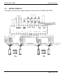
5.2
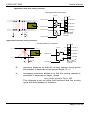
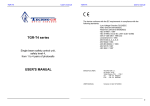
WIRING EXAMPLE.
Connection of two F3S-A light curtains to the control unit F3SP-U2P-TGR.
Sync.2(-) (gray/black 6)
Sync.2(+)(gray 3)
Receiver
Emitter
F3S-A
Page 10 of 28
F3SP-U2P-TGR
User's manual
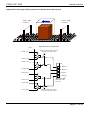
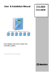
Connection of two F3S-B light curtains to the control unit F3SP-U2P-TGR.
RS-485(B) (Pink 6)
+
25
26
Receiver
F3S-B
14
GND
15
16
OUT1
OUT2
RX2
+
29
30
OUT RX2
A
B
31
32
RS-485(B) (Pink 6)
RS-485(A) (Grey 5)
RS-485(A) (Grey 5)
Emitter
OUT
GND
Vcc
OUT
GND
Vcc
OUT RX1
A
B
27
28
13
Output1 (Green 3)
Output1 (Green 3)
12
N.C.
Output2 (White 1)
N.C.
24
N.C.
23
11
C
MUTING
SENSOR
RX1
22
Output2 (White 1)
+
21
Instability (yellow 4)
Vs (Brown 2)
N.C.
20
Interlock selection (yellow 4)
Vs (Brown 2)
GND (Blue 7)
Relay monitoring (White 1)
Ext. test (Green 3)
N.C.
19
10
D
MUTING
SENSOR
TX2
18
GND (Blue 7)
TX1
+
17
9
A
GND (Blue 7)
8
B
MUTING
LAMP
RESET
OUT
GND
Vcc
OUT
GND
Vcc
7
Instability (yellow 4)
Vs (Brown 2)
6
Interlock selection (yellow 4)
5
GND (Blue 7)
4
+24VDC GND
Vs (Brown 2)
3
SAFETY
OUTPUT 1
SAFETY
OUTPUT 2
Ext. test (Green 3)
2
MUTING
LAMP
Relay monitoring (White 1)
1
TEST SWITCH
+24VDC GND
RESET SWITCH
+24 VDC
MUTING SENSORS
Emitter
Receiver
F3S-B
Page 11 of 28
F3SP-U2P-TGR
User's manual
Notice
•
•
•
•
•
•
•
•
•
•
To configure the control unit in such a way that it works with one single
light curtain, it is necessary to connect the terminal 31 and 32 to the
terminal 29.
DC power supply units must satisfy all the conditions below in order to
conform to the application directives.
1) The power supply voltage should be within rating (24VDC+/- 10%)
2) The power supply conforms to EMC Directive (industrial environment)
and LOW-Voltage Directive.
3) The power supply uses double insulation between the primary and
secondary circuits.
4) The power supply should include over current protection limited up
to 4 A.
5) The power supply maintains an output holding time of at least 20ms.
The transformer which is necessary to power the system must
conform to standard EN 60742 (double insulation) or with equal
insulation, for instance VDE 0551.
It is necessary to protect the control unit with an outer fuse having a
nominal interruption current equal to 1 A.
The TEST and RESET buttons must be positioned in such a way that
the operator can see the protected area when he restarts, or carries
out a test or override operation.
The muting lamp for signalising “active muting” must be positioned in
a place where it can be seen from any operative point.
Read the paragraph relating to the muting function and its use for the
positioning of the activation sensors of this function.
Both safety contacts OUT1 and OUT2 must be connected. If the
machine has a single locking circuit, the two normally opened contacts
must be connected in series.
The connection cables of the light curtains, of muting request, test and
reset must be masked with minimum section 22AWG. The cable
shield braids must be all earthed on the control unit side.
Be sure to isolate the power prior to wiring.
Page 12 of 28
F3SP-U2P-TGR
6
User's manual
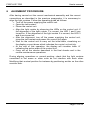
ALIGNMENT PROCEDURE.
After having carried out the correct mechanical assembly and the correct
connections as described in the previous paragraphs, it is necessary to
align the light curtains. Follow the operating guide as follows:
• Turn off the power supplying the control unit.
• Open the test contact.
• Power the control unit.
• Align the light curtain by observing the LEDs on the control unit: If
the alignment of the light curtain 1 is correct, the LED 1 and 2 are
turned on. If the alignment of the light curtain 2 is correct, the LED 3
and 4 are turned on.
• After the alignment, turn off the power supplying the control unit,
close the test contact and power the control unit again.
• Wait for the control unit to carry out the initial tests, visualising on
the display a count-down which indicates the control unit activity.
• At the end of this operation, the display will visualise letter ‘A’
indicating the active state of the control unit.
• Carry out all the checks described in the final checks and in the
routine maintenance operations.
During aligning operations or normal working, check that the light curtains
connected to the same or other units do not interfere with each other.
Modifying their mutual position for instance by positioning emitter on the other
receiver side.
Page 13 of 28
F3SP-U2P-TGR
7
User's manual
OPERATING PROCEDURES.
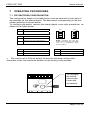
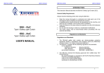
7.1 DIP-SWITCHES CONFIGURATION.
The configuration shown in the table below must be selected on both sets of
dip-switches on the internal board. The description corresponding to the prechosen selection is shown below.
To configure dip-switch, remove the lateral plastic cover with screwdriver as
shown in the figure below.
SW 1
Function
1
X
SW 2
4
not used
1
2
3
Function
2
Off
muting A-B act on the light curtain 1.
On
muting C-D act on the light curtain 2.
Forbidden
Function
3
ON
ON
3
2
1
4
NOTE: Configure the two dipswitch in the same way,otherwise
code '8' is displayed, which
m eans a failure.
4
function
Off
muting 60 s
Off
interlock mode
On
muting ∞ s
On
automatic mode
• The control-unit is Factory default set with the following configuration:
Automatic mode, the maximum duration of the muting: sixty seconds.
To configure
dip-switch,
remove this
cover with
screwdriver
Page 14 of 28
F3SP-U2P-TGR
7.2
7.2.1
User's manual
MUTING FUNCTION.
DESCRIPTION.
The muting function makes it possible to inactivate one or both light curtains in
order to allow, for instance, the objects passage without stopping the machine.
As required by the standard, the control unit has two inputs for the activation of
this function. Two separate muting functions are present.
It is necessary to position and connect the muting sensors in order to avoid
undesired muting inputs. It is important to remember that the muting function
forces the system to work and for this reason it must be used with care.
To use the muting function, it is necessary to connect the muting lamp,
otherwise the control unit is locked.
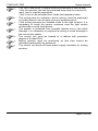
7.2.2
INSTALLATION CRITERIA
1
2
3
4
The muting sensors must recognise the material (namely pallets,
vehicles, etc.) over its full length.
The sensors must be arranged in such a way that the material is
recognised even when it is on a pallet or other transporting medium.
In case of different transport speeds through the muting area,
consideration must be used on the muting duration.
All the light curtains and the muting sensors must be arranged in
such a way that the previous material has already passed the last
muting sensor before the new material has reached the first muting
sensors.
Muting
lamp
Test & Reset
button
F3SP-U2P-TGR
control-unit
Light cable
Power cable
Muting cable
RX cable
TX cable
Page 15 of 28
F3SP-U2P-TGR
User's manual
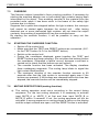
Application with four muting sensors:
Muting sensors connection:
24 VDC
contact of A1
L
v
B2 A2
S
B1 A1
N.C.
11 MUTE C
N.C.
10 MUTE D
contact of A2
9 MUTE A
contact of B1
8 MUTE B
d1
F3SP-U2P-TGR
terminals
D
contact of B2
Application with two muting sensors:
Muting sensors connection:
24 VDC
contact of A
B
N.C.
11 MUTE C
N.C.
10 MUTE D
9 MUTE A
8 MUTE B
A
S
d1 = D
contact of B
F3SP-U2P-TGR
terminals
D:
minimum distance so that the muting sensors keep active
the request; it depends on the parcel length: D < L.
d1:
necessary maximum distance so that the muting request is
accepted; it depends on object speed:
dmax [cm]= v[m/s] x 3[s] x 100
This distance must not allow both sensors and the muting
cycle with the passage of a person.
Page 16 of 28
F3SP-U2P-TGR
User's manual
Application with eight muting sensors for output and input control
Safety light
curtain 2
D2 C2
D1 C1
Safety light
curtain 1
B2 A2
B1 A1
Muting sensor connection:
24 V DC
contact of C1
Muting enable to light curtain 2
from robot system control
contact of C2
contact of D1
11 MUTE C
contact of D2
10 MUTE D
9 MUTE A
contact of A1
8 MUTE B
contact of A2
F3SP-U2P-TGR
terminals
contact of B1
contact of B2
Muting enable light curtain 1
from robot system control
Page 17 of 28
F3SP-U2P-TGR
•
•
•
•
•
•
•
User's manual
The TEST and RESET buttons must be positioned in such a way,
- that the operator can see the protected area when he carries out
reset, test or override operations.
- that it can not be activated from inside the hazardous area.
The muting lamp for indication “active muting” must be positioned
in a place where it can be seen from any operative point.
If the muting sensors are installed close to the light curtains, it is
necessary to install the sensor receivers near the light curtain
emitter side to avoid interference.
The system is protected from possible failures due to the cable
damage; it is necessary to prepare the wiring to avoid damage to
the connection cables.
The control unit must be located in a cabinet with protection
degree of at least IP54.
Muting sensors must be positioned so that they cannot be
activated inadvertently by personnel.
The control unit does not have power supply terminals for muting
sensors.
Page 18 of 28
F3SP-U2P-TGR
7.3
7.4
User's manual
OVERRIDE.
This function makes it possible to force a muting condition, if necessary by
starting the machine despite one or both safety light curtains having been
interrupted by the object. Thus enabling removal of the material from the
protected area, when it has been stuck in the beam of the safety light
curtains due to a failure.
Suppose that a pallet has stopped before the light curtains; the conveyor
belt cannot be started again because the control unit - after having
detected one or more interrupted light curtains- will not close the output
contacts, thus making it impossible to free the controlled area.
By starting the override function, it will be possible to carry out this
operation.
STARTING THE OVERRIDE FUNCTION.
• Switch off the control unit.
• Make sure that the TEST and RESET buttons are connected. (N.C.
for the TEST button, N.O. for the RESET button).
• Switch on the control unit
• During the countdown displayed, press together the TEST and
RESET buttons and keep pressing. (Do not press the buttons before
the countdown. Otherwise a failure occurs, because a self-test is
carried out to check that the buttons are not locked ).
• The override function has been activated. The display visualises
three overlapping segments. The muting lamp blinks to signal the
light curtain disconnection.
• The maximum duration of the override function amounts to 60
seconds after that the light curtain is connected again even if the
buttons are pressed. If the buttons are released before this time has
elapsed, the override function will be immediately stopped.
7.5
MUTING RESTRICTIONS (muting function).
a) The muting operation must occur according to the correct timing
sequence. For the two muting channels, it is necessary to activate
input MUTE_A or MUTE_C at first and then input MUTE_B or
MUTE_D within 3 seconds. If not, the muting sequence will not be
activated. A wrong sequence on muting shows a failure on the display
and the output contacts are open, until the RESET button is activated.
Page 19 of 28
F3SP-U2P-TGR
User's manual
b) When the muting state is active, an object can remain for a period of
no longer than 60 s., otherwise the muting function is switched off.
This mechanism is optional and can be deactivated when the control
unit is set up. (see page 13)
c) For the cases, the muting function is automatically disabled because
of time-out, the request must be cut-out (override function, or
removing object and rest) to generate the following muting state.
MUTE_A
30 ms min
MUTE_B
3s
max
ON
MUTE_STATE
OFF
OFF
∞ / 60 s max
It is not possible to carry out a muting request, if the light curtain is interrupted
and the output contacts are in the opened state ('E' or 'F' code on display,
beams are interrupted).
7.6
LED INDICATOR.
The operator can see the control unit status by a bicolour LED, four green
LEDs, and a 7-segment display.
The LEDs have following meanings:
• RED / GREEN LED (bicolour LED)
- RED : The safety light curtain/s detect an object, or
the control unit detects an error, which can be possibly
recovered by pressing the RESET button, and the output
contacts are opened.
- GREEN : The safety light curtain/s are working correctly and there are
no detected objects, and the output contacts are closed.
• Four GREEN LEDs
- When they are lit, the safety light curtain/s work normally and no
object is detected, the output contacts are closed.
• 7-segment display
See sec. 12, the description of the coding is given.
Page 20 of 28
F3SP-U2P-TGR
8
User's manual
FINAL CHECKS.
Check that the area protected by the safety light curtain is free from any
obstacle; check the correct triggering of the output contacts opening by
interrupting the protection rays (red LED switched on, controlled machine
stopped). CAUTION! If the red LED switches on and off, check the correct
mechanical installation.
NOTE. This check must be repeated each time you move or
mechanically re-align the safety light curtains and muting sensors.
9
ROUTINE MAINTENANCE.
Be sure to conduct inspection checks as below regularly.
• Check that there is no person in the hazardous area before operator
turns ON the power.
• Check that the unit locks by inserting a moving object through the
detection zone.
• By opening the test contact, check that the output contacts are opened
(red LED switched on and machine stopped).
• Make sure that the access to the hazardous areas is not possible from
any non-protected area and that the minimum distance from the safety
light curtain to the hazardous part is not less than the result calculated
with reference to the formula reported at paragraph 4.1.
• Make sure the installation satisfies one of following conditions;
1) The machine connected to the control unit has an interlock function.
2) The controller uses interlock mode.
3) It is not possible for a person to stop between the safety light curtain
and the hazardous parts of the machine.
• Make sure that there is no outer damage to the safety light curtain
and/or the outer electrical connections.
• Make sure that the response time, including the safety light curtain and
the machines, does not exceed the established limits.
• If failure occurs, all functions of the control unit shall be tested.
The frequency of these operations depends on the special applications and
operative conditions.
Page 21 of 28
F3SP-U2P-TGR
10
User's manual
GENERAL INFORMATION AND USEFUL DATA.
Safety MUST be part of our consciousness.
The safety devices are only effective if installed correctly by respecting the
guidelines laid down in the relevant standards.
These devices should be installed by a competent person. Please contact our
office for advise on service or installation.
Problems due to voltage interruption on the power supply may cause
temporary openings of the outputs. This is not damaging to the safety PES
and control unit.
The guarantee is complete for a period of 12 months starting from the delivery
date of the device.
Defects which are clearly due to damage caused by an incorrect use,
accidental causes or catastrophic events are not covered by the guarantee.
In case of failure, send the light curtain to your distributor (See the back cover)
Please indicate the detected failure and the operational period.
Page 22 of 28
F3SP-U2P-TGR
11
User's manual
TECHNICAL DATA.
• This is following the combinable light curtains;
Type 4 light curtain: F3S-Axxx series
Type 2 light curtain: F3S-Bxxx series
Note that all safety light curtains to be used are certified according with the
EN61496-1 Type 4/ Type 2
• al input: 420 mA max. (for any model).
• Voltage: 24 Vdc ± 10%.
• Number of light curtains: 2 pairs max.
• Indicators: 4 green LEDs, 1 green/red LED.
• 1-digit display (diagnostic).
• Response time: <= 18 ms
• Working temperature: -10 a + 55 °C.
• Moisture: from 15% to 95% (not condensing).
• Output contacts: 2 NO, 3.15 A max, 250 Vac, cosϕ 0.6 ÷1 (protected by a
resettable fuse).
• Outer controls: test, reset, muting and override.
• Container: plastic container for installation on a din/omega guide.
• Protection class of control unit: IP 20.
• Protection class of the cabinet containing the control-unit: IP54 at least.
• Weight: control unit 600 g.
• Features of fuses relay board: F1-F2, internal resettable fuses 3.15A T
250V.
• Features of fuses muting lamp: internal resettable fuse 315mA T 250V.
• Muting lamp: incandescent lamp 24 V, 3 W min, 300 mA max.
Page 23 of 28
F3SP-U2P-TGR
User's manual
12 INDICATION CODES
12.1 INDICATION IN NORMAL OPERATION
CODE
DESCRIPTION
H
Initial test is activated
8 -> 1
Count-down during the initial test.
U
Test button is pressed. Output contacts are opened.
≡
Override function is activated.
A
Normal cycle: Output contacts are closed.
E
Light curtain is interrupted in automatic mode: Output
contacts are opened.
F
Interlocked condition: Output contacts are opened.
12.2 INDICATION FOR TROUBLE SHOOTING.
CODE
DESCRIPTION
Action
7
Error of muting lamp
1
8
Irreversible system error or error on the
output contacts.
2
9
Wrong muting sequence request.
3
Page 24 of 28
F3SP-U2P-TGR
User's manual
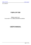
If failure code is shown on the display, the user must only carry out the
procedures indicated in the column relating to that failure and described as
follows
1. check that the muting lamp is not blown or incorrectly connected,
otherwise contact your distributor (to replace the fuse, follow the
instruction on paragraph 10).
2. this type of failure means that the unit cannot be used and it is
necessary to contact your distributor.
3. check the correct wiring and sensor positioning for muting
sequence
Indirect discharge with 6kV or direct discharge with 8kV may cause
influence to the 7-segment display and the output contacts may open; this
situation does not compromises the safety functioning of the light curtain.
Page 25 of 28
F3SP-U2P-TGR
User's manual
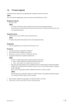
13 OVERALL DIMENSIONS.
FRONT VIEW
SIDE VIEW
120 mm
Control unit
F3SP-U2P-TGR
150 mm
TOP VIEW
75 mm
Page 26 of 28