1
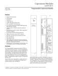
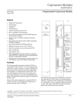
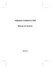
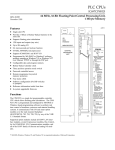
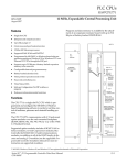
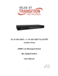
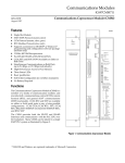
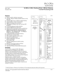
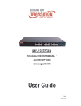
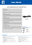
This Datasheet for the
IC697BEM711
Bus Receiver (Required for Each Local Expansion Rack)
http://www.qualitrol.com/shop/p-14752-ic697bem711.aspx
Provides the wiring diagrams and installation guidelines for this GE Series 90-30
module.
For further information, please contact Qualitrol Technical Support at
1-800-784-9385
support@qualitrol.com
1
Bus Expansion Modules
IC697BEM711
64
Bus Receiver Module
GFK-0162F
August 1997
Bus Receiver Module (IC697BEM711)
datasheet GFK-0162F
Features
a44453
D High Speed Parallel Bus Expansion Interface
D Supports up to seven Expansion racks
D Supports Hold Last State
D System Fault Isolation
D Three LED indicators provide module, termination, and bus expansion port status
D No DIP switches to set, easy software configuration into PLC system
Functions
This Bus Receiver Module (BRM) permits expansion
from the main rack to a maximum of seven additional
IC697 PLC racks with up to 50 feet (15 meters) total of
interconnecting cable.
The module occupies a single slot and has two connectors, one for attachment to the upstream or CPU rack
and the other for a daisy chained arrangement to additional expansion racks. The Bus Receiver Module must
always be installed in slot 1.
Three green LEDs provide status indication of module
status, rack activity status and presence of the I/O Bus
Terminator Plug (IC697ACC702) which is required in
the last rack.
The Bus Receiver Module supports hold last state operation of the output modules in the event of loss of
communications with the CPU. It also permits isolation and repair of a faulty module within a rack.
ÎÎÎÎ
ÎÎÎÎ
Î
ÎÎÎÎ Î
ÎÎÎÎ
Î
ÎÎÎÎ
Î
ÎÎÎÎ
Î
ÎÎÎÎ
Î
ÎÎÎÎ
Î
ÎÎÎÎ
Î
ÎÎÎÎ
Î
ÎÎÎÎ Î
ÎÎÎÎ
Î
ÎÎÎÎ
Î
ÎÎÎÎ
Î
ÎÎÎÎ
Î
ÎÎÎÎ
Î
ÎÎÎÎ
Î
ÎÎÎÎ
Î
ÎÎÎÎ
Î
ÎÎÎÎ
Î
ÎÎÎÎ
Î
ÎÎÎÎ
Î
ÎÎÎÎ
Î
ÎÎÎÎ
Î
ÎÎÎÎ
Î
ÎÎÎÎ
Î
ÎÎÎÎ
OK
LAST RACK
BUS ACTIVE
BUS
RECEIVER
ÎÎ
ÎÎ
Î
ÎÎ ÎÎ
ÎÎ
Î
ÎÎÎ
ÎÎ
Î
ÎÎ
Î
Î
ÎÎ
ÎÎ
ÎÎ
ÎÎ
Î
Î
ÎÎ
Î
ÎÎ
Î
ÎÎ
Î
ÎÎ
Î
ÎÎ
Î
ÎÎ
Î
ÎÎ
Î
ÎÎ
Î
ÎÎ
Î
ÎÎ
Î
ÎÎ
Î
ÎÎ
Î
ÎÎ
Î
ÎÎ
Î
ÎÎ
Î
ÎÎ
Î
ÎÎ
Î
Î
ÎÎ
Î
Î
BEM 711
RACK
CONFIGURED
TERMINATION
INSTALLED
EXPANSION
PORT ENABLED
ON = OK, ENABLED
MODULE FUNCTION
BUS RECEIVER
HIGH SPEED
INTERFACE FROM
IC697 EXPANSION
RACKS TO IC697
MAIN RACK
EXPANSION
PORT IN
(TOWARDS CPU)
TO BEM 711
OR BEM 713
50 FT. MAX. TOTAL
CABLE LENGTH
FROM BEM 713 TO
LAST BEM 711
EXPANSION
PORT OUT
(AWAY FROM CPU)
TO BEM 711
INSTALL
TERMINATOR
PLUG IN LAST
RACK IN CHAIN
USE IC697ACC702
USE THIS MODULE
IN FIRST SLOT ONLY
MODULE
IC697BEM711
LABEL
44A726758–201
The BRM must be configured into the IC697 PLC system using the MS-DOSr or Windowsr programming
software configuration function.
r MS-DOS and Windows are registered trademarks of Microsoft Corporation.
t
Series 90 -70 Programmable Controller Data Sheet Manual
GFK-0600F
64-1
Bus Expansion Modules
2
GFK-0162F
August 1997
Bus Receiver Module
Installation
Terminator plug
D Installation should not be attempted without refer-
The terminator plug which is supplied with each BRM
is only required in the last BRM in the chain as shown
in figure 2. It may be discarded or saved as a spare if
this BRM is not at the end of the chain.
ring to the applicable Programmer Controller Installation Manual (see reference 3).
D Make sure rack power is off.
D Insert label inside module access door (see figure 2).
D Install in slot 1 of the rack.
D Select expansion rack ID on rack with BERG jumpers (see figure 1).
Module Mechanical Keying
This module includes a mechanical key that prevents
inadvertent substitution of one module type for
another in a given slot. The key fits a uniquely
shaped area on the board below the connector. The
key is included with each module.
D Turn on power.
Rack Number Jumpers
When the Bus Receiver Module is installed the remote
rack ID must also be set up. This is done with the
BERG jumpers located behind the power supply as
shown in figure 1. For more details, see Chapter 3 of
the Programmable Controller Installation Manual.
a42823
ÎÎ
ÎÎ
ÎÎ
If this BRM is at the end of the chain, the terminator
plug is installed in the lower expansion port, which is
labeled EXPANSION PORT OUT. The plug should be
secured with its attached screws.
When the module is first installed, the key latches
onto the backplane center rail. When the module is
extracted, the key remains in the center rail, configuring the slot to accept only identical module types.
Expansion Rack Attachment
Using cable IC600WDxxxA (where xxx is length in
feet as shown in figure 2) a Bus Transmitter Module
(BTM) in the CPU rack connects to a BRM in an expansion rack. Additional expansion racks are added
by daisy-chaining cabling between BRMs.
Removing a Module
01
8
The instructions below should be followed when removing a module from its slot in a rack.
4
RACK NUMBER =2
D Grasp the board firmly at the top and bottom of
2
1
the board cover with your thumbs on the front of
the cover and your fingers on the plastic clips on
the back of the cover.
D Squeeze the rack clips on the back of the cover
with your fingers to disengage the clip from the
rack rail and pull the board firmly to remove it
from the backplane connector.
Figure 1. Rack Number Jumpers (Rack 2 Selected)
64-2
D Slide the board along the card guide and remove it
from the rack.
t
Series 90 -70 Programmable Controller Data Sheet Manual
GFK-0600F
Bus Expansion Modules
3
GFK-0162F
August 1997
Bus Receiver Module
ÎÎ
ÎÎ
ÎÎÎ
ÎÎ
ÎÎÎ
ÎÎ
ÎÎÎ
ÎÎ
Î
ÎÎ
ÎÎ
ÎÎ
Î
Î
Î
Î
ÎÎ
ÎÎÎÎ
ÎÎ
ÎÎ
Î
ÎÎ
Î
ÎÎ
Î
ÎÎ
Î
ÎÎ
ÎÎÎÎ
Î
Î
ÎÎ
ÎÎ
Î
ÎÎ
Î
ÎÎ
Î
ÎÎ
Î
ÎÎ
ÎÎÎÎ
Î
Î
Î
ÎÎÎÎÎÎ
ÎÎÎ
ÎÎÎ
ÎÎÎ
Î ÎÎÎÎÎÎÎÎ
ÎÎÎÎÎÎÎÎ
ÎÎ
ÎÎ
Î
ÎÎ
Î
ÎÎ
Î
ÎÎ
Î
ÎÎ
ÎÎ
ÎÎ
Î
ÎÎ
ÎÎ
Î
ÎÎ
Î
ÎÎ
Î
ÎÎ
Î
ÎÎ
ÎÎ
ÎÎ
Î
ÎÎ
ÎÎ
ÎÎÎ
ÎÎ
ÎÎÎ
ÎÎ
ÎÎÎ
ÎÎ
Î
ÎÎ
ÎÎ
Î
Î
Î ÎÎ
ÎÎ
ÎÎ
Î
Î
Î
Î
ÎÎ
ÎÎ
ÎÎ
Î
ÎÎÎÎÎÎ
ÎÎÎ
ÎÎÎ
ÎÎÎ
Î
ÎÎ
ÎÎ
Î
ÎÎ
Î
ÎÎ
Î
ÎÎ
Î
ÎÎ
ÎÎ
ÎÎ
Î
ÎÎ
Î
ÎÎ
Î
ÎÎ
Î
ÎÎ
Î
ÎÎ
ÎÎ
Î
ÎÎ
Î
ÎÎ
Î
ÎÎ
Î
ÎÎ
Î
Î
Î
ÎÎ
ÎÎ
Î
ÎÎ
Î
ÎÎ
Î
ÎÎ
Î
ÎÎ
ÎÎÎÎÎÎ
ÎÎÎ
ÎÎÎ
ÎÎÎ
Î
ÎÎ
ÎÎ
Î
ÎÎ
Î
ÎÎ
Î
ÎÎ
Î
ÎÎ
ÎÎ
ÎÎ
Î
ÎÎ
ÎÎ
Î
ÎÎ
Î
ÎÎ
Î
ÎÎ
Î
ÎÎ
ÎÎ
ÎÎ
Î
Î
ÎÎ
ÎÎ
Î
ÎÎÎ
ÎÎÎ
ÎÎÎ
ÎÎÎ
Î
ÎÎ
Î
Î ÎÎ
ÎÎ
ÎÎ
Î
ÎÎ
Î
ÎÎ
Î
ÎÎ
Î
ÎÎ
ÎÎ
ÎÎ
Î
ÎÎÎÎÎÎ
ÎÎÎ
ÎÎÎ
ÎÎÎ
Î
PARALLEL
a42786g
PROGRAMMER
RACK 0
P
S
C B
P T
U M
a42987
G
B
C
or
N
B
C
ONE
METER
IC66* I/O BUS (7500 FEET (2285 METERS) MAXIMUM)
RACK 1
B
R
M
Î
Î
Î
Î
ÎÎ
Î ÎÎÎ
ÎÎÎ
Î
ÎÎ
Î
ÎÎ
Î
ÎÎÎÎ
ÎÎ
Î
ÎÎ
Î
Î
Î
Î
Î
Î
Î
Î
Î
Î
Î
Î
Î
Î
Î
Î
Î
ÎÎ
Î
ÎÎ
Î
LED STATUS
INDICATORS
P
C
M
BEM 711
RACK
CONFIGURED
IC66*
I/O BLOCK
RACK 6
NOTE
B
R
M
G
B
C
or
N
B
C
EXPANSION PORT IN,
CONNECT TO BEM713
OR NEXT BEM711
B
R
M
EXPANSION
PORT IN
(TOWARDS CPU)
TO BEM 711
OR BEM 713
I/O TERMINATOR
(LAST RACK)
CPU BRM BTM GBC/NBC PCM PS -
SELECTED CPU MODULE
BUS RECEIVER MODEL, BEM711
BUS TRANSMITTER MODEL, BEM713
BUS CONTROLLER, BEM731/734
PROGRAMMABLE COPROCESSOR MODULE, PCM711
POWER SUPPLY, PWR710/711/724/748
Figure 2. Typical PLC System Configuration
Status Indications
The three green LEDs provide status information as
shown in figure 3. The top LED is ON when power is
applied, the rack is configured, there are no fatal
faults present in the rack and communications are
established with the CPU, and there is at least one
other module in the rack. The middle LED indicates
the presence of the terminator plug: ON is plug present. The bottom LED is on when the CPU is in run
mode and has communicated with this rack within
the last 500 milliseconds, otherwise it is off. When this
light is out the output modules go to their configured
fault state (either On or Hold Last State)
t
Series 90 -70 Programmable Controller Data Sheet Manual
GFK-0600F
ON = OK, ENABLED
MODULE FUNCTION
RACK 7
LEGEND
EXPANSION
PORT ENABLED
BUS RECEIVER
HIGH SPEED
INTERFACE FROM
IC697 EXPANSION
RACKS TO IC697
MAIN RACK
IC66* I/O BUS (7500 FEET (2285 METERS) MAXIMUM)
ONE
METER
P
S
TOTAL LENGTH OF ALL INTERCONNECTING
CABLES FROM BTM TO LAST BRM IS 50 FEET
(15 METERS) MAXIMUM. ALL RACKS MUST BE
AT SAME GROUND POTENTIAL
(8 RACKS MAXIMUM).
TERMINATION
INSTALLED
EXPANSION PORT OUT
TO NEXT BEM711
(IF LAST RACK IN
CHAIN, INSTALL
TERMINATOR PLUG
HERE)
50 FT. MAX. TOTAL
CABLE LENGTH
FROM BEM 713 TO
LAST BEM 711
EXPANSION
PORT OUT
(AWAY FROM CPU)
TO BEM 711
INSTALL
TERMINATOR
PLUG IN LAST
RACK IN CHAIN
USE IC697ACC702
USE THIS MODULE
IN FIRST SLOT ONLY
MODULE
IC697BEM711
LABEL
44A726758–201
Figure 3. Bus Receiver Module - User Details
64-3
Bus Expansion Modules
4
GFK-0162F
August 1997
Bus Receiver Module
Table 1. References
Reference
1
2
3
Title
Programming Software User’s Manual
Programmable Controller Reference Manual
Programmable Controller Installation Manual
Table 2. Specifications for IC697BEM711 [
0.8 amps
Current required from 5V Bus
ExpansionInterfaceSpecification
Maximum cable length
50 feet (15meters)
Effective Data Rate
500Kbytes/sec
ElectricalIsolation
Non-isolateddifferentialcommunication.
System designed to support the VME standard C.1
VME
[ Refer to GFK-0867B, or later for product standards and general specifications. For installations requiring compliance to more
stringent requirements (for example, FCC or European Union Directives), refer to Installation Requirements for Conformance to
Standards.
Table 3. Ordering Information
Description
Bus Receiver Module
Terminator Plug
I/OCable
Catalog Number
IC697BEM711
IC697ACC702
IC600WD005A, 5 ft. (1.5m)
IC600WD010A, 10 ft. (3m)
IC600WD025A, 25 ft. (7.5m)
IC600WD050A, 50 ft. (15m)
Note: For Conformal Coat option, or Low Temperature Testing option please consult the
factory for price and availability.
64-4
t
Series 90 -70 Programmable Controller Data Sheet Manual
GFK-0600F