1
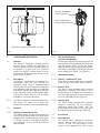
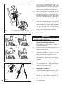
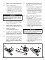
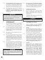
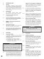
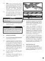
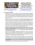
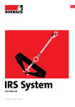
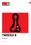
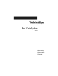
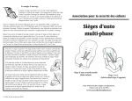
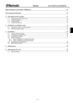
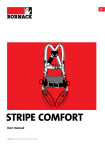
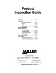
derope
®
emergency escape/controlled descent devices
ANSI Z359.4-07
CSA Z259.2.3, type 1E
use and
maintenance
instructions
derope® emergency escape/controlled descent devices
Contents
Page
First read the following warnings . . . . . . . . . . . . . . . . . . . . . . . . . . . . . . . . . . . . . . . . . . . . . . . .3
1.
Function and description . . . . . . . . . . . . . . . . . . . . . . . . . . . . . . . . . . . . . . . . . . . . . . . . . . . . . .6
2.
Limitation of the equipment . . . . . . . . . . . . . . . . . . . . . . . . . . . . . . . . . . . . . . . . . . . . . . . . . . . .8
3.
System component requirements . . . . . . . . . . . . . . . . . . . . . . . . . . . . . . . . . . . . . . . . . . . . . . . .9
4.
Installation . . . . . . . . . . . . . . . . . . . . . . . . . . . . . . . . . . . . . . . . . . . . . . . . . . . . . . . . . . . . . . . .10
5.
Operation . . . . . . . . . . . . . . . . . . . . . . . . . . . . . . . . . . . . . . . . . . . . . . . . . . . . . . . . . . . . . . . . .12
6.
Marking and labelling . . . . . . . . . . . . . . . . . . . . . . . . . . . . . . . . . . . . . . . . . . . . . . . . . . . . . . . .14
7.
Maintenance and storage . . . . . . . . . . . . . . . . . . . . . . . . . . . . . . . . . . . . . . . . . . . . . . . . . . . . .14
8.
Performance data . . . . . . . . . . . . . . . . . . . . . . . . . . . . . . . . . . . . . . . . . . . . . . . . . . . . . . . . . .16
9.
Inspection . . . . . . . . . . . . . . . . . . . . . . . . . . . . . . . . . . . . . . . . . . . . . . . . . . . . . . . . . . . . . . . .16
10. Warranty information . . . . . . . . . . . . . . . . . . . . . . . . . . . . . . . . . . . . . . . . . . . . . . . . . . . . . . . .17
11. Inspection check list . . . . . . . . . . . . . . . . . . . . . . . . . . . . . . . . . . . . . . . . . . . . . . . . . . . . . . . .17
LIRE D'ABORD CET AVERTISSEMENT
LEER ESTA ADVERTENCIA PRIMERO
Il est essentiel pour sa sécurité que l'utilisateur
comprenne intégralement le présent guide avant d'utiliser
le dispositif. Une mauvaise compréhension de ce guide
peut entraîner un risque mortel. L'utilisateur qui ne
comprend pas couramment l'anglais doit recevoir
l'information équivalente d'un spécialiste de la sécurité ou
de son superviseur.
Es necesario, para su propia seguridad, que el usuario lea y
comprenda integramente este manual antes de utilizar el
dispositivo. Si no se asimila bien este manual, puede tener
como consequencia riesgo mortal. Si el usuario no
comprende suficientemente el inglés, es necesario que
tenga la información equivalente por parte de un especialista
en seguridad o de su responsable superior.
The Derope® emergency escape/contolled descent device is only part of a total fall protection system
and the use of compatible hardware and components is mandatory. The system components must meet
local, state, federal and provincial regulations before being incorporated in a personal fall protection
system. It is imperative for the safety and efficiency of operations that this manual be read and fully
understood by the worker before using any fall arrest system. ALL instructions contained herein must
be carefully read and strictly followed for proper use and maintenance of the equipment. Alterations or
misuse of this product, or failure to follow instructions can result in serious injury or death. If you have
any concerns or questions, please contact your distributor or Tractel® Ltd.
IN AN ENVIRONMENT WHERE A FALL HAZARD EXISTS,
SAFETY IS A MATTER OF LIFE OR DEATH FOR WORKERS AND BYSTANDERS.
This instruction manual is intended to meet the “Manufacturer’s Instructions” as required by ANSI and
CSA and should be used as part of an employee training program as required by OSHA.
It is neither a regulations compliance guide nor a general training guide for fall arrest, work positioning
or travel restraint systems. You must refer to instructions delivered by manufacturers of the pieces of
equipment included in your system. Whenever calculations and specific installations are required, the
worker should be professionally trained to that end and should secure relevant information prior to
commencing such work.
FIRST READ THE FOLLOWING WARNINGS
PRIOR INFORMATION
I.
It is the operator’s responsibility, and their employer’s responsibility if they operate under an
employer’s control, to strictly conform to the following warnings and to the instructions in this
manual. Doing otherwise would place any incident and its consequences under their responsibility.
II.
It is imperative, for safety and efficiency reasons, that this manual be read and fully
understood by the operator before using the Derope® emergency escape/controlled descent
device, and that all the instructions contained herein be followed accordingly.
III.
This manual should be available at all times to all users. Keep these instructions handy for easy
reference whenever required. Extra copies are available from Tractel® Ltd.
IV.
Never operate the Derope® emergency escape/controlled descent device if any warning,
operating or capacity instruction affixed to the device, as shown in this manual (Figure 15,
page 15), are obscured or missing. In such case contact Tractel® Ltd. for supply of label or
exchange of the unit (for stamped instructions) under commercial conditions.
V.
The emergency escape/controlled descent equipment must be placed under the authority of a
competent person being fully trained and aware of the applicable safety regulations for use,
maintenance, overhaul and control of the equipment for any professional use.
VI.
Equipment associated with the use of the Derope® emergency escape/controlled descent
device must comply with applicable safety regulations, either local, state, federal and regional,
and be compatible with one another and with the Derope® emergency escape/controlled
descent device as described in this manual. This includes all parts that constitute the rescue
equipment, especially the harness, lanyard, lifeline and connecting equipment. Tractel® Ltd.
denies liability for any incident due to non compliance of components not sold or not
recommended by Tractel® Ltd.
TRAINING AND QUALIFICATION
VII.
Do not use the Derope® emergency escape/controlled descent device unless properly
trained by an authorized trainer. A fall could result in serious injury or death.
VIII.
Health condition of the operator must be compatible with a possible fall arrest operation of the
system used.
IX.
Before operating, a worker should be:
a) Mentally and physically fit for the purpose, especially at heights or in confined spaces
b) Free from the influence of alcohol or drugs
c) Competent for the job to be performed
d) Familiar with the equipment and all applicable safety rules, regulations and requirements
e) Trained under safe conditions for working under the above requirements
X.
Training must be extended to maintenance, control and overhaul. It must be carried out under
safe conditions excluding risk of fall. The training of the operator must be extended to a proper
rescue procedure which must be set up in writing under the authority in charge of the
equipment by a competent person or technical consultant according to work conditions. Contact
Tractel® Ltd. for training information.
3
FIRST READ THE FOLLOWING WARNINGS
CONTROL AND MAINTENANCE
XI.
The installation of the Derope® emergency escape/controlled descent device must be carried
out under safe conditions according to the applicable local, state, federal and regional
regulations.
XII.
The installation of the Derope® emergency escape/controlled descent device must be
completed by a competent person to ensure that the anchorage is adequate, according to the
applicable safety regulations, and that it can safely bear the dynamic loads applied in case of
fall arrest.
XIII.
Every time the operator is to be connected to the rescue system, inspect the Derope®
emergency escape/controlled descent device and the associated equipment. Ensure it is in
good condition, as explained in this manual (section 9). Never operate the equipment if
damage is detected. Check that the anchoring of the Derope® emergency escape/controlled
descent device is safe and adequate for the load and the type of operation, according to
applicable regulations.
XIV.
The operator must connect to the Derope® emergency escape/controlled descent device in a
safe zone, away from any unprotected edge, in a safe and stable place for getting connected,
according to the applicable safety regulations.
XV.
A careful and regular inspection of the Derope® emergency escape/controlled descent device
and of the associated rescue equipment is part of the maintenance requirements for safe
operation, especially under site conditions. Keep the device clean and free from dirt. Thorough
overhaul servicing is available from Tractel® Ltd.
XVI.
Tractel® Ltd. declines any responsibility for the consequences of dismantling or altering the
Derope® emergency escape/controlled descent device beyond description in this manual, by
anyone who is not authorised by Tractel® Ltd. Tractel® Ltd. declines any responsibility for the
consequence of repair having been carried out beyond its control.
XVII.
Except for the operations described in this manual, the maintenance and repair of Tractel® Ltd.
equipment, must be exclusively performed by authorised (written approval) Tractel® Ltd.
service center or by Tractel® Ltd.
XVIII.
Should the responsible authority decide that a piece of equipment is no longer suitable for use,
take precautions in disposing of it so that it cannot be re-used. Satisfactory inspections should
be entered in the provided inspection log.
OPERATION
4
XIX.
Always consider and control the specific risks related to the nature of the job that is subject to
a rescue.
XX.
Ensure that the Derope® emergency escape/controlled descent device is properly secured
to the structure before every operating session. The Derope® emergency escape/controlled
descent device must be fastened with components specified by Tractel® Ltd.
XXI.
Prior to the use of the equipment described in this manual, it is imperative that you ensure that
there are no obstacles within the evacuation trajectory or risk of contact with a dangerous
surface.
XXII.
The Derope® emergency escape/controlled descent device must be positioned in a manner
that will not interfere with the self aligment of the unit or prevent the proper rotation of the
handwheel. The lifeline must be allowed to travel freely without any interference by the setup
of the Derope® emergency escape/controlled descent device.
FIRST READ THE FOLLOWING WARNINGS
XXIII.
Refer to the rescue plan put in place by the person responsible for the intervention site before
using the device.
XXIV.
Tractel® Ltd. recommends that all operators/rescue workers be equipped with a
communication device allowing them to issue an emergency signal in case of an incident.
XXV.
The Derope® emergency escape/controlled descent device must be used only for evacuation
or rescue purposes, as described within this manual. No other use of the device is authorized.
More specifically, the device must never be used as a suspension device or as part of a fall
protection system.
XXVI.
The Derope® emergency escape/controlled descent device is designed to be used by one or
two (1 or 2) persons. The combination of the user(s) weight, clothing and tools must not be less
than 66 lbs. (30 kg) and must not exceed 500 lbs. (225 kg).
XXVII.
A maximum of two persons can be connected on one Derope® emergency escape/controlled
descent device. The supporting structure must be adquate to bear the required efforts.
XXVIII.
Tractel® Ltd. assumes no liability for the adequacy of particular installations incorporating the
Derope® emergency escape/controlled descent device, beyond the information and description
given in this manual.
IN CASE OF EVACUATION OR RESCUE
XXIX.
The rescue operation should not take more than 15 minutes. Longer delays may endanger the
safety and health of the person to rescue.
XXX.
The rescue procedure must be carried out by rescuers trained in accordance with the rescue
procedure, according to the fall arrest work environment.
XXXI.
The Derope® emergency escape/controlled descent device and associated equipment
must be removed immediately after service.
XXXII.
Equipment must be returned to Tractel® Ltd. for inspection and re-verification.
SYMBOLS AND CODE WORDS USED IN THIS MANUAL
DANGER
immediate or possibly imminent danger that will lead to serious injuries or death.
WARNING
immediate or possibly imminent danger that could lead to serious injuries or death.
CAUTION
possibly dangerous situation leading to minor or moderate injuries.
NOTICE
possibly dangerous situation leading to damage to equipment or surroundings.
Always concerned to improve the quality of its products, the Tractel® Group
reserves the right to modify the specifications of the equipment described in this manual.
5
Descent deceleration
using the pig tail
Arrest configuration
using the jamming cleat
Evacuation operation from cable car cabin
Fig. 1
1.
FUNCTION AND DESCRIPTION
1.3.2
1.1
Function
The Derope® emergency escape/controlled
descent device enables the evacuation or
rescue of persons from an elevated position to
the ground or a lower level at a controlled
speed. The Derope® descent device is not to
be used as a fall arrest system or part of a fall
arrest system (Figure 1).
Descent deceleration
or arrest configuration
By having the rope pass through the pig tail, the
rescue worker can manually decrease and even
stop the descent action. To lock the device,
simply insert the rope trough the jamming cleat.
This feature is standard on all Derope® descent
device models from Tractel® Ltd. (Figure 2).
1.3.3
Attachment feature
1.2
6
Fig. 2
Description
The Derope® descent device is composed of a
Kernmantle® rope that goes through the
reinforced casing where a centrifugal brake
limits the descent speed. Snap hooks located at
each extremity of the rope allow for accelerated
evacuations. Pig tails and a jamming cleat give
users even more control on the descent speed.
Cooling fins ensure that the unit is rapidly
available for consecutive descents.
1.2.1
The descent speed is automatically limited to
235 ft./min. (72 m/min.) for a single user
through the operation of the centrifugal brake.
1.3
Features
1.3.1
Hoisting or lowering function
This feature allows a victim to be lifted by the
rescue worker with the help of the hand wheel
equipped with a folding handle. Lifting speed
is 3 ft./min. (1 m/min.). This option is available
on the Derope® Up A, Up E and Up R descent
device models.
1.3.3.1 Derope® T and Derope® Up A
These devices can be attached by a carabiner
located on top of the device (Figure 3 and 4).
1.3.3.2 Derope® Up E
This device comes equipped with a bracket
designed to stabilise the Derope® Up E
descent device on a ladder. The bracket locks
onto two rungs and must be anchored with the
use of an adjustable lanyard (Figure 5).
1.3.3.3 Derope® Up R
This device comes equipped with a bracket
designed exclusively for the Tracpode™
positioning tripod from Tractel® Ltd. This
bracket must be fastened to one of the legs of
the tripod with the fastening pin (Figure 6).
1.4
Accessories
1.4.1
Carryring bag
The carrying bag is designed to house the
Derope® descent device with up to 330 ft.
(100 m) of rope. This bag allows for easy
access to the equipment as well as easy
Adjustable lanyard to
secure the system
Rope adjuster
Carabiner
Pig tail
Carabiners
Pig tail
Jamming
cleat
Casing
Upper
clamp jaw
Kernmantle® rope
(Descent extremity)
Anchor pin
Lower
clamp jaw
Kernmantle® rope
(Ascending
extremity)
Index
device
Self-locking
snap hook
Knurled knob
Derope® T
Fig. 3
Derope® Up E
Fig. 5
Hand wheel
Rope blocking
device
Folding
handle
Rope guide
Safety pin
Locking
screw
Fastening pin
Fig. 4
Derope® Up A
Fig. 6
Derope® Up R
7
transportation in the event of an intervention
or rescue situation.
1.4.2
In-line pulley
Pulley equipped with two aligned sheaves,
designed for evacuation on a tensioned rope.
1.4.3
Rigging plate
The rigging plate is used to fasten several
connectors to a single fastening point. The
plate allows for orienting and distributing the
load during rescue operations.
1.5
Technical specifications
See Table 1 below.
2.
LIMITATION OF THE EQUIPMENT
2.1
Maximum two workers per Derope® descent
device.
2.2
Capacity
The Derope® descent device is rated to be used
with a minimum of 66 lbs. (30 kg) and a
maximum of 500 lbs. (225 kg). The combination
of the user(s) weight, clothing and tools may not
exceed 500 lbs. (225 kg).
2.3
Descent
For repeated descents, use of the Derope®
descent device is limited with respect to load,
descent height, and number of repeated
descents in accordance with the limits indicated
in the table below. See Table 2 below.
DANGER
Only the Tractel® Ltd. Kermantle® that comes with
the device is authorized for use with the Derope®
descent device. This rope can be customized for
lengths ranging from 30 to 1,300 ft. (10 to 400 m).
DANGER
Following each use, whether for a single descent
or repeated descents, the Derope® descent device
must be inspected by a technician trained and
qualified for this operation.
Table 1
Model
Derope® T
Derope® Up A
Max. height for
single descent
Derope® Up E
Derope® Up R
1 person: 1,300 ft. (400 m)
2 persons: 650 ft. (200 m)
Speed of descent
1 person: 235 ft./min. (72 m/min.)
2 persons: 295 ft./min. (90 m/min.)
Temperature
-31 to 122° F (-35 to 50° C)
Dimensions
(H x L x D)
6 ⁄16 x 4 ⁄32 x 4 ⁄8 in. 8 ⁄64 x 77⁄8 x 61⁄2 in. 1929⁄32 x 107⁄16 x 61⁄2 in. 193⁄32 x 107⁄16 x 61⁄2 in.
(170 x 120 x 105 mm) (225 x 200 x 165 mm) (485 x 265 x 165 mm) (485 x 265 x 165 mm)
Construction
Housing: aluminum casting
Internal parts (pulley and gears): heat-treated steel
Hand wheel winch
11
23
1
55
n/a
n/a
Max load: 310 lbs. (140 kg)
Applied force: 11 lbs. (5 kg)
Capacity
1 person: 310 lbs. (140 kg)
2 persons: 500 lbs. (225 kg)
Weight
4 lbs. (1.9 kg)
6.6 lbs. (3 kg)
13.4 lbs. (6.1 kg)
3
Kernamntle rope
14.3 lbs. (6.5 kg)
⁄8 in. (9.5 mm) Tractel Ltd. Kernmantle
®
Standards
®
®
ANSI Z359.4-07 and CSA Z259.2.3, type 1E
Table 2
Maximum number of repeated descents
Descent height
8
< 165 ft.
(50 m)
< 410 ft.
(125 m)
< 650 ft.
(200 m)
< 1,000 ft.
(300 m)
< 1,300 ft.
(400 m)
Capacity of
310 lbs. (140 kg)
16
6
4
2
2
Capacity of
500 lbs. (225 kg)
6
2
1
1
Prohibited
DANGER
The combined descent height must be monitored.
If the combined descent height exceeds the limits
indicated in Table 2 below, regardless of the time
taken to reach this combined descent height, the
descent device must be overhauled as instructed
in section 9 by a technician trained and qualified
for this operation.
2.3
2.4
Corrosion
The Derope® descent device has been
designed with corrosion resistant materials.
However it should not be left for long periods
of time in environments where corrosion could
take place. If corrosive environments such as
sewage, fertilizer or seawater are unavoidable,
increase frequency of inspections to ensure
that the integrity of the rescue equipment
remains uncompromised.
Electrical hazards
Take extreme caution when working near or
around high voltage power lines: electricity
can pass through the metal components of the
equipment resulting in electrocution.
2.5
Explosive environment
The Derope® descent device is not to be used
in a potentially explosive environment.
2.6
Temperature
The Derope® descent device is intended for
use in an environment ranging from -31° to
122° F (-35° to 50° C).
2.7
Chemical hazards
The user is responsible for keeping the lifeline
out of exposure to damage such as chemical
hazards and/or abrasion.
2.7.1
Each application should be evaluated taking
into consideration the following:
a) type of acid/alkali
b) exposure conditions
c) concentration
d) temperature
2.7.2
Paint can penetrate into the weave and dry,
causing the rope to become hard, brittle and
eventually break the fibers. Solvents and
drying agents within paint cause damage
similar to chemical exposure.
2.7.3
Exposure to chemicals may cause equipment
malfunction. If your equipment will be exposed
to chemicals and you are unsure of the effects
on your equipment, please contact Tractel® Ltd.
2.8
Moving machinery
Take extreme caution when working near or
around moving machinery.
2.9
Sharp edges/Abrasion
Contact with sharp edges or abrasive surfaces
should be avoided. Cushion or otherwise
protect against product contact.
2.10
Sunlight
All organic fibers, either natural or man-made,
will degrade to various degrees from exposure
to ultraviolet light. Precautions should be taken
to store equipment away from prolonged
exposure to sunlight, fluorescent lights and
other source of ultraviolet radiation.
2.11
Product life
Any Derope® descent device showing
excessive wear or degradation shall be
removed from service and returned to an
authorized dealer for inspection. See inspection
information (section 9) for further information.
3.
SYSTEM COMPONENT REQUIREMENTS
3.1
Environmental hazards must be considered in
selecting the appropriate lifeline, harness and
lanyard. Questions about using the Derope®
descent device where chemicals, high
temperature or other unusual conditions exist
should be addressed to Tractel® Ltd.
3.2
Anchor system
An anchorage point is a secure point of
attachment for a personal fall arrest system.
It must be identified by a qualified or
competent person. It has to be independent of
Make sure there is no obstacle
in the evacuation path
Fig. 7
9
the means of supporting the worker. For
rescue purposes, the anchorage point must
support a minimum of 3,100 lbs. (13.8 kN) per
attached worker. Consult local, state, federal
and provincial regulations as revisions occur.
Fig. 8
Every anchorage point must be selected with
care. Make sure that there are no obstacles in
the evacuation path and on the landing zone.
Maintain a safe distance from any obstruction
to ensure a safe descent (e.g. electric wires,
glass, concrete reinforcing bars) (Figure 7).
3.2.2
Never use an anchorage point which will not
allow the snap hook keeper to close. Anchor
must be compatible with snap hook and must
not be capable of causing a load to be applied
to snap hook keeper. Before each use, ensure
that all connectors are in good working
condition and safely closed, especially the
gates on the snap hook and/or carabiner.
4.
INSTALLATION
Derope® Up E mounted on ladder
a.
b.
Index
pin
c.
3.2.1
WARNING
The Derope® descent device must only be installed
and used by a trained technician.
d.
4.1
Derope® T and Derope® Up A emergency
escape/controlled descent devices
An inspection as per section 9 must be
performed before use.
4.1.1
Identify or prepare the anchorage point for the
Derope® descent device.
4.1.2
Make sure that the anchorage point can
withstand a minimum of 3,100 lbs. (13.8 kN)
and is located above the evacuation point.
4.1.3
Attach the Derope® descent device to the
anchorage point with the help of the supplied
carabiner.
4.1.4
Throw the rope down, making sure that there
are no entanglements or knots, that the rope
does not come in contact with sharp edges
and that it reaches the ground.
4.2
Derope® Up E emergency
escape/controlled descent device
Inspect the ladder uprights and rungs for signs
of deformation.
4.2.1
Set up the upper clamp jaw onto the ladder
rung at the desired position to perform the
rescue (Figure 8a).
4.2.2
Bring the lower clamp jaw up to the closest
rung (Figure 8b).
Fig. 9
Fig. 10
10
Derope® Up R mounted on tripod
4.2.3
Thighten in place using the knurled knob
located on the side of the bracket (Figure 8c).
4.2.4
Install the adjustable lanyard:
a) Run the adjustable lanyard through the
ladder structure located above the device,
going around one of the uprights and an
upper rung at the same time (Figure 8e).
b) Connect the lanyard onto the rope adjuster
(Figure 8f).
c) Pull on the rope to tighten around the
anchoring structure.
WARNING
The Derope® Up E descent device must always be
secured with an adjustable lanyard on a separate
anchorage point. Ensure the ladder has sufficient
load bearing capacity.
4.2.5
Throw the rope down, making sure that there
are no entanglements or knots, that the rope
does not come in contact with sharp edges
and that it reaches the ground.
4.2.6
Align the Derope® descent device in the
required direction by modifying the position of
the anchor pin in the indexing device (Figure 9).
4.3
Derope® Up R emergency
escape/controlled descent device
4.3.1
4.3.2
The Derope® Up R descent device must be
attached to one of the legs of a Tracpode™
positioning tripod from Tractel® Ltd. as shown
on Figure 10. Any other form of attachment to
the Tracpode™ positioning tripod is prohibited.
In order to use the Derope® Up R descent device
on one of the three legs of the Tracpode™ tripod,
the latter must be equipped with a diverter
pulley or two (2) pulleys if another piece of
equipment is used on the same Tracpode™
tripod (e.g.: Blocfor® self-retracting lanyard or
work winch).
4.3.3
To install the Derope® Up R descent device on
the Tracpode™ positioning tripod from
Tractel® Ltd., set up the equipment by following
these instructions:
a) Unscrew the screw securing the hook by
which the bracket is fastened to the
Derope® Up R descent device (Figure 11a).
b) Install the Derope® Up R descent device on
the fastening hook (Figures 11b and 11c).
c) Screw in the locking screw to prevent the
unit from separating from its bracket
(Figure 11c) and check that it is properly
positioned and tightened.
4.3.4
When the Derope® Up R descent device is
installed on the bracket used with the
Tractel® Ltd. Tracpode™ tripod:
a) Lay the Tractel® Tracpode™ tripod folded
on the ground.
b) Adjust the legs of the Tractel® Tracpode™
tripod to obtain the desired height: see
user manual for Tracpode™ tripod.
c) Choose the leg on the Tractel® Tracpode™
tripod carrying an idler pulley at the top;
withdraw the locking pin from this leg.
d) Position the bracket rigging hole in line
with the locking hole on the Tractel®
Tracpode™ tripod.
CAUTION
Caution with respect to assembly direction: the
rope blocking device must be pointing towards the
top of the Tracpode™ tripod (Figure 10).
e) Install the fastening pin for the bracket used
with the Derope® Up E descent device. The
fastening pin ensures two functions: lock the
Tracpode™ tripod leg and secure the bracket
for the Derope® Up R descent device on the
tripod leg (Figure 12a, page 12).
f) Lock the fastening pin using the safety pin
(Figure 12b, page 12).
g) Fully unfold the three legs of the
Tracpode™ tripod.
Fig. 11
11
h) Remove the ball pin located above the idler
pulley at the top of the Tracpode™ tripod
(Figure 12c).
i) Run the rope of the Derope® descent
device around the idler pulley (Figure 12d).
j) Fit the ball pin to prevent the rope from
coming out of the idler pulley (Figure 12e).
k) Open the rope blocking device on the
bracket (Figure 12f).
l) Insert the rope coming out of the Derope®
descent device in the rope blocking device
of the bracket (Figure 12g).
m) Throw the rope down, making sure that
there are no entanglements or knots, that
the rope does not come in contact with
sharp edges and that it reaches the ground.
n) Close the rope blocking device (Figure 12h).
5.
OPERATION
5.1
Before use
Functionally check the Derope® descent device
by manually pulling the rope in the device over
a minimum length of 3 ft. (1 m) in both
directions to make sure that the resistance
during movement increases with the speed of
movement.
Fig. 12
12
WARNING
Always use a self-locking snap hook for an
attachment in any personal rescue system.
5.2
Evacuation function
During a intentional vertical evacuation, the
person must not move away by more than 20°
with respect to the vertical axis to avoid any
excessive swinging effects. The anchor point
must be above the evacuation area.
5.2.1
After you have installed the Derope® descent
device in compliance with the instructions in
section 4, proceed as follows:
a) Fasten the person to be evacuated or hook
yourself up by the connector at the end of
the evacuation strand of the Derope®
descent device to a fall-arrest harness.
b) Pull the free strand of the rope to tension
the evacuation strand.
c) Run the free strand of the rope through the
rope guide then through the jamming cleat.
d) If necessary, check that the handwheel
handle on the Derope® Up descent device
models is folded in.
e) Place the person to be evacuated above
the open space. The person will not
descend since the rope is blocked by the
jamming cleat.
f) Start the descent by releasing the free
strand of the rope in the jamming cleat.
g) Descent may be interrupted by firmly
grasping the free end of the lifeline.
h) Once the person has reached the ground,
unfasten the person from the harness.
i) Position the other end of the lifeline taut with
no slack before attaching to the next person
to descend.
j) Ensure the Derope® descent device has
properly cooled before its next use.
5.3
5.4
5.4.1
Evacuation on a cableway descent
If it is not possible to evacuate the victim
vertically due to an obstruction, the evacuation
can be carried out down a cableway positioned
at an angle between 30° and 60° (Figure 13).
a) The rescuer secures two anchor slings to
the structure. The higher anchorage to be
used for the cableway and the lower point
for the Derope® descent device.
b) Attach the victim to the descent rope of the
Derope® descent device and to the cable
way using the 1-ft. (30 cm) lanyard.
c) Two persons on the ground tension the
cableway in the direction of travel to avoid
any obstructions.
d) Release the descending rope from the
jamming cleat and monitor the descent
until the victim is on the ground.
Hoisting or lowering function
After the Derope® decent device has been
properly secured above the victim as
described in section 4, the self-locking snap
hook at the extremity of the rope must be
hooked into the frontal or back D-ring on the
full body harness of the victim and secured.
WARNING
Ensure that the free end of the Kenmantle® rope is
inserted in the jamming cleat.
5.4.2
The handle is folded out from the handwheel
and the handwheel is then rotated in the ‘UP’
or ‘DOWN” direction in order to hoist or lower
the victim to a safe recovery platform or up to
a point where the victim can be released from
his fall protection sub-system.
5.4.3
The rope located in the jamming cleat must be
kept tight during the hoisting of the victim with
the hand crank in order to prevent an
unintentional descend.
5.4.4
Fold the handle back into the handwheel. Pull
the rope located in the jamming cleat out of
the jamming cleat and lower the victim.
Pig tail
Derope®
Ascending end
of the Derope®
Descending end
of the Derope®
Lanyard
The rope between the device and the person to
be lowered/hoisted must not have any slack;
the free rope on the other side must be pulled
downwards with force. The free end of the
trailing rope is inserted in the aluminium pig tail
so that it can be clamped in the jamming cleat.
30° to 60°
Fig. 13
Fig. 14
13
5.4.5
The rope removed from the jamming cleat
must be guided during the evacuation process
by allowing it to lightly slip through the hand.
The rope must be lead through the friction
diverter during the whole evacuation process.
5.4.6
The descending speed will be controlled
automatically by a centrifugal brake. It is also
possible to interrupt the descent by braking
(holding) the upward travelling trailing rope
with the hand.
5.5.5
Both persons can now evacuate by releasing
the rope being held. The descending speed will
be controlled automatically by a centrifugal
brake. It is possible to interrupt the descent by
holding the ascending trailing rope by hand.
6.
MARKING AND LABELLING
6.1
Read and comply with all markings and/or
labels on the Derope® descent device. The
markings and/or labels must be intact and
easy to read.
6.2
The Derope® descent device is marked and/or
labelled as shown in Figure 15.
WARNING
It must be ensured that the ascending rope does
not catch or hook on an obstacle as this would
consequently interrupt the evacuation process.
Ensure that the person(s) do not collide with an
obstacle during the descent.
WARNING
Never remove a label from a piece of equipment.
5.5
5.5.1
Simultaneous recovery
of victim and rescuer
The simultaneous evacuation of two persons
allows a victim to be lowered under
accompanying supervision (Figure 14, page 13).
The rescuer can descend simultaneously with
the victim when the rope reserve is already
located on the ground. This process is only
permitted up to a maximum evacuation height
of 650 ft. (200 m).
5.5.2
Both persons to be evacuated must wear a
full-body harness.
5.5.3
Upon anchoring the Derope® descent device to
a structural element with a sufficient loadbearing capacity, the rescuer ensures the
trailing rope is passed into the friction diverter,
so it can be clamped in the jamming cleat, and
descends to the victim while controlling the
trailing rope.
5.5.4
Upon reaching the victim, the rescuer attaches
the victim’s back D-ring to his own frontal
attachment point using a 1-ft. (0.3 m) lanyard.
Upon ensuring of the proper connection
holding the victim to the rescuer frontal
attachment point, the rescuer can cut the
victim’s lanyard from it’s anchorage point.
DANGER
Prior to releasing the fall protection sub-system,
usually a shock-absorbing lanyard, ensure the
victim is properly connected to the extremity of the
evacuation rope.
14
7.
MAINTENANCE AND STORAGE
7.1
Failure to maintain and store equipment
carefully can result in damage and malfunction
that could lead to serious or fatal injury.
7.2
Storage
The rescue equipment should be stored in a
dry and cool room and protected from UV light.
Avoid contact with acids, caustic liquids and
oils. Prior to storing rope ensure it has been
dried without any exposure to direct heat.
7.2.1
Prior to storing the rescue device an inspection
is recommended to allow a quicker access
when required. Upon meeting inspection
requirements the device should be stored in an
equipment bag that would prevent external
deterioration and allow proper transportation to
required site. The bag should be “locked” in a
manner to prevent any tampering and ensure
all the rescue equipment is ready for use.
7.3
Cleaning
Most of Tractel® Ltd.’s equipment can be
washed with a solution of cold water and mild
detergent. After washing and brushing with a
synthetic brush, rinse thoroughly with clear
water and hang to dry, out of the sun and away
from exposure to high heat. Metallic
equipment such as the Derope® descent
device and carabiner must be dried thoroughly
to avoid corrosion. Items can be washed
whenever needed to extend their lives. They
will also be easier to inspect for damage. Do
not use any cleaning solvent agents, acids etc.
as they may seriously damage the equipment.
Fig. 15
15
8.
PERFORMANCE DATA
8.1
Capacity
The Derope® emergency escape/controlled
descent device is designed to be used by one
or two (1 or 2) persons. The combination of the
user(s) weight, clothing and tools must not be
less than 66 lbs. (30 kg) and must not exceed
500 lbs. (225 kg).
8.2
Requirements
The Derope® descent device meets
ANSI Z359.4-07 and CSA Z259.2.3, type 1E.
8.3
Anchorage strength requirements
3,100 lbs. (13.8 kN).
8.4
Maximum allowed single descent height
Up to 1,300 ft. (400 m) for one person and up
to 650 ft. (200 m) for two persons.
8.5
Maximum allowed consecutive descent
height
See Table 2, page 8.
8.6
Nominal descent speed
235 ft./min. (72 m/min.) for one person and
295 ft./min. (90 m/min.) for two persons.
8.7
Hoisting/lowering height with hand wheel
The maximum hoisting/lowering distance with
hand wheel winch is 165 ft. (50 m).
9.
INSPECTION
9.1
Inspection schedule
A thorough inspection of the working
components is required by Tractel® Ltd. or an
authorized service center upon meeting one of
the following critiria:
a) One person: up to 3,280 ft. (1,000 m)
b) Two persons: up to 1,000 ft. (300 m)
c) Hoisting/lowering distance with hand
wheel winch: 165 ft. (50 m)
remove the item from service immediately and
replace it. If any damage or questionable
conditions are apparent and are not described
below, remove the item from service, replace it
and contact Tractel® Ltd. for advice.
9.2.1
If corrosive environments are unavoidable or
the units are to be used for training, increase
frequency of inspection to ensure that the
integrity of the system and its components
remains uncompromised.
9.2.2
Failure to remove equipment that has been
damaged or is in questionable condition could
lead to serious or fatal injury. A detailed record
of inspection should be maintained. See
pages 18 and 19 for suggested record sheets.
9.3
Devices at training facilities
When the Derope® descent device system is
used for training, greater care must be taken
to ensure the inspection is performed
thorougly by a competent person at the end of
each training day, even if the aforementioned
limit values for the inspection intervals were
not reached during the previous training.
WARNING
Training courses and exercises
Only trained competent personnel authorised by
Tractel® Ltd. may implement training courses and
exercises.
9.4
Components
9.4.1
Hardware and housing
All parts of the hardware, bracket and housing
should be inspected for rough or sharp edges,
corrosion, burrs, cracks dents and distortion.
Ensure the presence of all screws and that
they are properly tightened in position.
9.4.2
Rope entry and exit points
The wear at the rope entry/exit point must be
checked. The rope entry/exit point must not
show a wear greater than 5⁄64 in. (2 mm).
9.4.3
Handwheel
The handwheel should rotate freely without
resistance and turn evenly in the horizontal
plane without any wobble.
9.4.4
Carabiner
All parts of the carabiner should be free of
corrosion and distortion. The gate spring
should exert enough force to firmly close the
gate. Special attention must be paid to the
mechanism, which should close adequately.
The safety bar of the autolocking carabiner
must complete its rotation when closed.
WARNING
All stated limit values for the inspection intervals
apply only for devices and ropes that do not show
signs of wear. The above limits can be achieved by
the cummulation of use. Consideration must be
given not to surpass the above limits, inspections
should be performed prior to reaching the limits
and prior to storing the units for a next use.
9.2
16
A visual inspection must be completed prior to
each use. A competent person must inspect all
equipment periodically, at least once a year and
log all information relating to the inspection. If
damage is detected as described below,
9.4.5
9.4.6
Rope
The rope must be visually/manually inspected
along its entire length for the following wear
appearance/defects/damage; Cuts, broken
fibers, thickening, fraying, kinks, knots, rot,
burns, severe wear/abrasion, open, loosened
termination and sheath displacement
(Figures 16 and 17). The diameter must be
constant along the entire lenght of the rope.
Fibre breaks
Check that the Derope® descent device has
the required potential for the number of
consecutive descents, descent height and
evacuation load to carry out the operation
planned: see Table 2, page 8.
WARNING
Discoloration, fused, melted or brittle fibers may
indicate signs of chemical solvent, burning heat or
ultraviolet damage.
9.5
Fig. 16
GOOD
NOT GOOD
Fig. 17
10.5
Any defect in this equipment must immediately
be brought to the attention of Tractel® Ltd. The
distributor will make arrangements with the
factory for repairs or replacements of the parts
within the terms of this warranty.
10.6
Tractel® Ltd.'s obligation is restricted to
replacing parts and does not include the
complete unit. The warranty is void on any unit
that has been modified or tampered with,
repaired by persons other than a factory
representative or an authorized Tractel® Ltd.
distributor, repaired with other than Tractel® Ltd.
standard parts, or damaged by reasons of
accident, alteration, misuse or abuse.
10.7
This warranty is in lieu of all other warranties,
expressed or implied. We do not authorize any
person or representative to make any other
guarantee or to assume for us any liability in
connection with the sale of our appliances
other than those contained herein. Any
agreement outside of or contradictory to the
foregoing shall be void and of no effect.
11.
INSPECTION CHECK LIST
11.1
Inspection log for training facilities
The performed descending work must be
entered into the attached list for documentation
purposes. A differentiation between descending
and hoisting must be made.
For every other component, refer to appropriate
inspection instructions.
WARNING
Any equipment that fails to meet the above
inspection requirements shall be removed from
service. Only Tractel® Ltd. or persons or legal
entities authorized in writing by Tractel® Ltd., shall
make repairs to Tractel® Ltd. rescue equipment.
10.
WARRANTY INFORMATION
10.1
Tractel Ltd. warrants its equipment to be free
from defects in material and workmanship
under normal use and service.
10.2
Our obligation under this warranty is limited to
repairing or replacing, at our option, any part
of the unit, which proves under examination to
our satisfaction, to be defective in material or
workmanship. The item in question is to be
returned to Tractel® Ltd. upon authorization of
the distributor, transportation prepaid, within
twelve (12) months from the date the
equipment was sold to the original purchaser.
Return shipment must be prepaid.
®
10.3
Any parts proved to be defective, upon
inspection by Tractel® Ltd. will be repaired or
replaced at no cost.
10.4
The obligation under this warranty does not
include labor or transportation costs or
consequential damages of any kind.
Severe rope wear, wear with rope thickening
17
Derope® decent device model:
Serial number of the manufacturer:
Owner/User:
Date of purchase:
Date of inspection
18
First use:
Inspection results, details of identified defects
Signature of competent person
Derope® decent device model:
Product serial number:
Owner/Training facility:
Date of use
Result of visual
inspection
Evacuation
Hoisting height
height and
and weight of
weight of trainee
trainee
Trainer/User
Trainer’s
signature
Maximum number of repeated descents
Descent height
< 165 ft. (50 m)
< 410 ft. (125 m)
< 650 ft. (200 m)
< 1,300 ft. (400 m)
Capacity of
310 lbs. (140 kg)
16
6
4
2
Capacity of
500 lbs. (225 kg)
6
2
1
Prohibited
19
Contact the nearest Tractel® Ltd. office.
In the United States
1 800 561-3229
110 Shawmut Rd.
P.O. Box 188
Canton, MA 02021
Tel.: (781) 401-3288
Fax: (781) 828-3642
In Canada
(626) 937-6727
315 Cloverleaf Dr., Bldg E
Baldwin Park, CA 91706
Tel.: (626) 937-6727
Fax: (626) 937-6730
fallstop@tractel.com
1 800 561-3229
11020 Mirabeau St.
Montreal, QC H1J 2S3
Tel.: (514) 493-3332
Fax: (514) 493-3342
www.tractel.com
Fallstop® is a registered trademark of Tractel®.
Ref. 3912CD (P0000)-v03-0000-06/09
© 2009 Tractel®
Printed in Canada