1
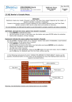
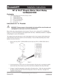
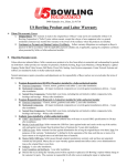
Steltronic
Focus
Maintenance
Manual
Rev-b
Steltronic S.p.A.
Via Artigianale 34, 25082 Botticino Sera
Brescia - Italy
Tel: +39 030 2190811 fax: +39 030
2190798
http://www.steltronic.com
Worldwide Service: + 39 030 2190830
Email: service@steltronic.com
US Steltronic: +1 (909) 287-0712
service.usa@steltronic.com
INDEX
Checking the Sciba (Camera) photocell
Checking the Sciba CCD
Substituting the Sciba CCD
Sciba CCD Mechanical calibration
Front Desk Touch Screen Calibration
Substituting a lane computer (VLC)
Steltronic focus- Maintenance Manual –rev b
Pg.
Pg.
Pg.
Pg.
Pg.
Pg.
03
04
10
11
18
19
2
Checking the Sciba photocell
The Sciba is equipped with 4 photocells (2 per lane) which are used to detect the passage of the ball
for the ball speed calculation and for the pinsetter commands. The Photocells are usually mounted
on the Sciba and in certain conditions directly on the Capping, the reflectors are mounted on the
small capping on the opposite side of the lane.
The pinsetter ball cushion micro switch is disconnected so that the pinsetter cycles when the scoring
system gives the command.
If the pinsetter does not cycle and the score does not advance, it is probable that the photocell has
lost its alignment.
BEFORE GOING TO CHECK THE PHOTOCELL ALIGNMENT CHECK THAT THE PINSETTER IS NOT
BLOCKED FOR REASONS THAT ARE NOT CONNECTED TO THE SCORING SYSTEM (cams badly
regulated, blocked motors, etc.)
If your system does NOT use the Sciba CCD camera for reading pin fall, (GS10, Vollmer String,
Vilati String, KF3000, Spellman string pinsetters) the only photocell is the one used for detecting the
ball to calculate the ball speed (except the KF3000, Vilati and Spellman string). If the pinsetter does
not cycle check the pinsetter sensors.
ATTENTION! TURN THE PINSETTER POWER OFF BEFORE MAKING THIS
CHECK.
Take the Sciba CCD protection cover off.
1 = Electronic and optical Sciba
CCD block.
2 = Photocells
3 = Signal board
4 = Support base
There is a RED LED behind each photocell: if the Red light id on
he photocell is lined up, if the Red Led is off the photocell is not
lined up.
In order to correctly align the photocell, loosen the 4 screws on
top of the photocell support and move the photocell, aiming at
the reflector on the other side of the lane until the red led comes
on.
When the Red Led comes on the photocell has been aligned.
For a perfect alignment we advise you to cover the reflector with a piece of paper leaving only a
small hole of about 2 cm in diameter in the centre of the reflector visible, in this way you are sure
that the photocell is ‘looking’ at the centre of the reflector. Repeat the operation for all 4 photocells.
If the Red Led goes off after the ball passes even after the photocell has been re-aligned then the
photocell may be pointing towards the border of the reflector.
Once the photocells have been checked (from a safe distance) test their functionality.
Steltronic focus- Maintenance Manual –rev b
3
Checking the Sciba CCD
By "checking the Sciba CCD" we mean, verify the direction the Sciba is pointing in respect to the
position of the pins. This operation is carried out at the Main Desk computer, without any
mechanical adjustments to the Sciba CCD itself.
The Sciba CCD is a “Linear camera” which ‘reads’ the pins on a “ideal line” as can be seen on the
above diagram. All 20 pins (2 lanes) can be seen on the ‘ideal line’. The ‘ideal line’ is at the neck of
the pins which, seen from 4 meters, is the point that the pins are furthest from one another.
IN ORDER TO OPTIMISE THE PIN COUNT BY THE SCIBA CCD WE ADVISE:
• Change pins that are damaged or broken at the neck.
• The neon lights on the lane pair must have the same brightness and intensity, any changes to
lighting should be made per pair of lanes.
• The Sciba is able to read (up to a certain point) even the ‘off spot’ pins, we suggest that the
pinsetter positioning arms be checked on a regular basis.
• Do not use pins which have black or coloured necks.
Turn the pinsetters on that need to be checked.
WAIT: the pinsetter pin deck light needs to warm up before giving the correct light.
The pinsetters should be on first ball with ALL 10 pins standing on each lane. The Sciba CCD is able
to see the red pins, we advise however to make the calibration settings with standard white pins.
Switch the hall lights on just like when there are bowlers; sometimes neon’s placed too close to the
pins change the light conditions and therefore the pin detection.
Enter in the FOCUS program, than open the Pins Detection calibration or click on
Camera icon in the lane manager menu.
Steltronic focus- Maintenance Manual –rev b
4
1
3
4
6
5
[1] Camera Icon: clicking directly on the icon, will send the configuration to the camera. This
button is used also for restart the communication with the camera, simply clicking on it.
[2]ON-LINE Status indication: when the link with lane computer and Camera is Ok, the status is
READY. If the Camera or the lane computer do not respond the status is FAILED.
[3]Camera parameters: clicking directly on this line will open the CAMERA PARAMETERS window.
In the Camera parameter window is possible change Brightness, Ratio, Frequency and Bank.
[4] [5] Lane selection: clicking on the tag will change the lane view selection
[6]GRAB IMAGE: clicking on GRAB IMAGE button will send a command to the camera for load in
memory a pins photo shot.
SUGGESTED OPERATIONS FOR FIRST CAMERA INSTALLATION (OR CAMERA
SUBSTITUTION):
•
•
•
•
Check the camera parameters
Select a lane side and Grab Image
Set Default position
Save PINS position
POST-INSTALLATION CAMERA CHECKING:
• Check the camera parameters
• Select a lane side and Grab Image
• Save PINS position
Steltronic focus- Maintenance Manual –rev b
5
CHECKING THE SCIBA (CAMERA) PARAMETERS
Clicking directly on the blue line will open the CAMERA PARAMETERS window.
Brightness: is the value given to the amount of light in the Sciba area. By lifting or lowering this
value you let more or less light into the Sciba, just as if it where a standard camera diaphragm. a
default settings is 4 (40 Ms).
Ratio: is the light variation when the pin has been knocked down. In practical terms if the ratio is
set to 50, the Sciba CCD will detect a pin as fallen when the light, in the area where the pin was
when the first photo was taken, varies by at least 50%. This parameter need to be change only in
EXTREME situation (pins dirty or light too dark), the default value is 50
Frequency: refers to the amount of ‘Hertz’ electricity. Set the value in accord to your local AC
frequency: EUROPE = 50 HERTZ
USA= 60 HERTZ CHINA=50 HERTZ
Bank: the BANK is a conventional “point” for pre-set a brightness value. Bank 1 is used for saving
the brightness value for white light.
During ‘glow in the dark’ bowling the pinsetter neon is turned off, the only light is a ‘black’
florescent light. The Brightness set for the white light is not enough for the camera to see the pins
correctly. It is necessary to increase the light that enters the camera by lifting the BRIGHTNESS
value. In order to make the operation quicker, a second ‘Bank’ (2 or 4) is assigned to the Glow
settings (with higher integration time).
FIRST OPERATION: select the current ‘bank’ which is needed for this calibration: 1 or 3 for with
light, 2 or 4 for glow bowling. Click on CHANGE BANK button to confirm. The screen will come back
to main menu.
SECOND OPERATION: once again click on blue line for opening the camera parameters window,
vary (if necessary) the Brightness or other parameter, then click on SAVE PARAMETERS to confirm
and exit.
Steltronic focus- Maintenance Manual –rev b
6
GRAB THE IMAGE AND SAVE THE PINS POSITION
First select one lane side, than clicking on GRAB IMAGE button will send a command to the camera
for load in memory a pins photo shot.
The Screen shot of the lane
is load as a graphic. All the pins cursor are
overlapped on right side of the screen.
Click on SET DEFAULT POSITION BUTTON
The pins cursor will be displayed on the
approximate position.
To Moving the pins cursor, click on the pin number button, keep the mouse button pressed,
move to left or right the cursor, for finish the operation realise the mouse button.
The pins are represented by the ‘peaks’ of different heights. The height depends on the distance
from the neon light the pin is. Pins 1,3,2 and 5 are the highest ‘peaks’ as these pins are closet to the
light, while pins 7,8,9 and 10 are further away and therefore receive less light resulting in lower
‘peaks’. As the example shows the 10 pin ‘peak’ height is 100, less than half of the height of the pin
1 ‘peak’ (250).This is okay but a ‘peak’ lower than 50 would not be detected.
The yellow vertical window shows the searching area where Sciba looking for the pin. The windows
must be in the centre of the base of the peak, it’s mandatory that all the near window’s do not
overlap each other, otherwise the Sciba cant’ read the right pins.
At the end of the operation click on SAVE PINS POSITION button, than wait till the Save pins
position button became invisible, it’s means that the pins position is saved.
REPEAT THE STEPS FOR THE OTHER LANE SIDE
Steltronic focus- Maintenance Manual –rev b
7
CONFRONT IMAGES
Note: this operation is required only for installation with One Sciba per one pair of lanes
(STANDARD), for a odd lane installation confront image is not necessary.
1) Select ODD (or EVEN) lane, grab the image clicking on
GRAB IMAGE button.
2) Select EVEN (or ODD) lane, grab the image clicking on
GRAB IMAGE button.
3) Click on CONFRONT IMAGE button.
The snapshot picture displays the graphic of both lane together. The height of the peaks must be
similar: for example, pin 10 of odd lane, is approximately the same height of pin 10 of even lane.
If the difference between the 2 lanes is too much, probably the camera is rotate clock-wise or anti
clock-wise.
SUGGESTIONS FOR A GOOD PINS READING
It is important that the pins ‘peaks’ are a good distance from one another so that the pin detection
is good. In cases where it is difficult to get good peaks, move the window slightly to allow more
distance between them.
If the Sciba CCD position is not correct or the ‘focus’ is out it can be regulated, the worst thing is the
overlap of pin peaks, causing the Sciba CCD to detect one pin in place of another on the ‘ideal line’
and scoring it incorrectly.
Brightness value is same for both lanes. Depending by pins illumination’s condition, even and odd
lanes could display different peaks height, for same pins. It’s important to keep a Brightness media
value in order to calibrate both lane as well.
It is also possible, when the Brightness is too high, that the light saturates the lens and the peaks
overlap (they tend to become one line at the top).
If it is not possible to fix the problem by altering the Brighteners you need to MECHANICALLY
CALIBRATE THE SCIBA; If this does not work, replace the Sciba CCD.
The higher the peak is the more the peak tends to flatten. This phenomenon is known as IMAGE
SATURATION when a pin peak is too saturated the Sciba CCD tends to ‘see’ the pin even when it has
been knocked down.
Set the light that enters into the Camera by changing the Brightness.
If the pin ‘peaks’ are too high, being saturated with light, the Sciba CCD tends to ‘see’ them all the
time, if the pin ‘peaks’ are too low the Sciba CCD has a hard time ‘seeing’ them.
Integration time is the value given to the amount of light in the Sciba area. By lifting or lowering this
value you let more or less light into the Sciba, just as if it where a standard camera diaphragm.
Steltronic focus- Maintenance Manual –rev b
8
EXAMPLE OF WRONG CALIBRATION
The peaks are too LOW; not enough light is entering the lens and the Sciba does not recognize the
pins. Lift the Brightness
The peaks are too high; too much light is entering the lens; the Sciba recognizes the pins ALL the
time, even when they have been knocked down. Decrease the Brightness.
The peaks are overlapped; the Sciba recognizes one pin in place of another, or worse it recognizes
the pin in place of the one next to it. The Sciba may be out of focus. Lover the Brightness.
IF THE OPERATION IS NOT SUCCESSFUL MAKE A MECHANICAL CALIBRATION.
Steltronic focus- Maintenance Manual –rev b
9
Substituting the Sciba CCD
The Sciba CCD is made up of two parts:
The HEAD [1] that contains the electronics and lens.
The BASE [2] which supports the photocells and the
interface board.
More often than not it is not necessary to change the
entire Sciba CCD assembly, nor the entire Sciba
head.
If done carefully it is possible to change the
electronic part only without doing a mechanical
calibration.
TO CHANGE THE SCIBA ELECTRONICS WITH LENS
ATTENTION! Turn the power off to the lane computer or turn the I-Retro off
(only if I-Retro with direct power model)
Take the plastic cover off ( use a screwdriver to disconnect the 9 pole plug). Remove the aluminium
lid by unscrewing the 4 lateral screws. Remove the 3 screws (A, B and C) that hold the lens ring.
SLIGHTLY loosen ONE of the 2 fixing bolts (D or E). DO NOT LOOSEN THEM BOTH SO THAT YOU
MAINTAIN THE CALIBRATION POSITION.
Carefully remove the electronic boards from the back of the block, if necessary loosen one the bolts
a little more.
INSERT THE NEW BLOCK (lens + electronic boards), turn it until it positions itself against the bolt (D
or E) which you did NOT loosen, then tighten the loose bolt firmly.
Replace the lens ring and tighten the 3 screws tightly, without exaggerating replace the lid.
Before calibrating the Sciba from the Main Desk computer click on the SET
PREDEFINED button on the Sciba settings screen to load the original
settings.
Proceed with the calibration from the Main Desk computer. If, during the replacement, the Sciba has
moved, return to the mechanical calibration.
It is advisable, once checked that the position of the Sciba is correct, to use ordinary nail varnish to
block the bolts and screws. Don’t use substances which ‘permanently’ fix the screws and bolts as
this will make it impossible to service when required.
Steltronic focus- Maintenance Manual –rev b
10
Sciba CCD Mechanical calibration
This type of calibration is necessary if the Main Desk Computer calibration has failed because it’s not
possible to find an ideal position for the vertical pin lines (sign that the Sciba has moved or needs to
be replaced)
BEFORE DOING THIS TYPE OF OPERATION ASK FOR ADVISE FROM YOUR SUPPLIER OR
FROM YOUR AUTHORIZED SERVICE CENTRE
Take the pins off the pin deck and position the calibration boards supplied during installation. Check
if the pinsetter neon is switched ON and that the light conditions are the same as when there are
bowlers. Obscure any lights that may effect the pins which are not usually present.
Warning!
Placing the template on the lane deck is dangerous with pinsetter motor on.
Before to proceed, disconnect all pinsetter motor
keep only the pinsetter pins light on
Unplug the pinsetter motor connectors, than switch on the 2 pinsetters. Before to begin, please wait
some minutes cause the pit light must be hot.
The template should be placed symmetrically near the border of the pins spot as shown in the next
diagrams. Position depends also by lane installed:
•
•
Standard installation: one Sciba per one pair of lane
ODD installation: one Sciba per each lane
Standard Installation: one Sciba per one pair of lane
Standard Template position
Installation with ODD lane: Sciba mount at the right side of the lane
Steltronic focus- Maintenance Manual –rev b
11
ODD Template position
Installation with ODD lane: Sciba mount at the left side of the lane
ODD Template position
BEGIN THE MECHANICAL CALIBRATION
With the Sciba in calibration mode, LED 10 starts flashing and the other LED’s indicate how the
position should be adjusted, if adjustment is required. The machine is correctly adjusted when all
four GREEN LED’s are lit.
Activation of calibration mode for standard Sciba installation
(one Sciba for one pair of lanes)
Move the switch on Sciba
board in CALIBRATE
MODE(on top)
Steltronic focus- Maintenance Manual –rev b
12
Activation of calibration mode for ODD Sciba installation
(one Sciba for each lane)
Set the
Move the switch on Sciba
number 1
board in CALIBRATE
switch of S1 to
MODE(on top)
“ON” (Dip
Switch) and
leave it on
BEGIN TO ADJUST MANUALLY THE SCIBA
The scan line can be mechanically adjusted in three ways:
1) Rotation on its vertical axis
2) Rotation on the optical axis
3) Raising / lowering the scan line.
First loosen (a little bit) all the mounting bolts.
Adjustments should be carried out in the following order - first the vertical axis, then the optical axis
and lastly the height. The Led’s indicate in which direction the Sciba should be adjusted. After each
adjustment, tighten the relative adjustment bolt.
Steltronic focus- Maintenance Manual –rev b
13
MECHANICAL CALIBRATION: ROTATION ON IT’S VERTICAL AXIS
WARNING! MOVE THE SCIBA LITTLE BY LITTLE [ PUSH VERY GENTLY THE SCIBA BY ONE SIDE,
WAIT THE RESPONSE FROM THE LED, THEN PROCEED AS NECESSARY].
OK! THE VERTICAL AXIS IS ADJUSTED CORRECTLY. LOCK THE NUT.
If both LED 1 and LED 3 are lit, it means that the Sciba
cannot identify the marker sheets:
1] Check the Sciba position (maybe the Sciba is placed at the wrong distance)
2] TRY TO CHANGE THE INTEGRATION TIME: the neon light (from pinsetter) is not enough or is too
much for the Sciba; try to implement more integration time 1 by 1 or 2 by 2 and try to make the
calibration. If the problem persist decrease the integration time.
Steltronic focus- Maintenance Manual –rev b
14
MECHANICAL CALIBRATION: ROTATION ON THE OPTICAL AXIS
Allen key type bolts, on the front of the Sciba (the three projecting bolts, not to be confused with
the two, more flush bolts used to set the lens when it has been focused) must be loosened. After the
adjustment close STRONGLY.
OK! ROTATION ON OPTICAL AXIS CALIBRATE SUCCESSFULLY!
CLOSE VERY TIGHT THE 3 BOLT.
IF IS HARD ADJUST THE OPTICAL AXIS:
Try to lose or thigh the BOLT as indicated in the diagram in left side, then
adjust the Sciba.
Steltronic focus- Maintenance Manual –rev b
15
MECHANICAL CALIBRATION : RAISING/ LOWERING
ALL DONE! THE SCIBA IS NOW FULLY MECHANICALLY ADJUSTED.
When the Sciba has been correctly adjusted, the above three green LED’s (central in each of the
settings) remain on, the 10th LED stops flashing also remaining on.
WARNING!
Replace the calibration switch in OFF
position, or the Detection Device does not
works and gives message TIME OUT! On
the console (in the scanning mode).
Steltronic focus- Maintenance Manual –rev b
16
SUGGESTIONS ABOUT PINS POSITIONS
Each of the pins must be fully visible by the Sciba (not partly hidden by other pins).
The distance between the following pairs of pins is of vital importance:
• pins 1 and 8 on the left lane
• pins 4 and 7 on the left lane
• pins 1 and 9 on the right lane
• pins 6 and 10 on the right lane
The distance between each pair may not be enough, and although moving the Sciba may improve
the view, it may, in the same instant make the view of another two pins worse, so it is usually
better to move the pins (slightly).
E.g. Improving may alter and vice versa. As improving may alter the view of and vice
versa.
Some problems that may arise, with hard to see pins and how to solve them.
and (vital)
Move the Sciba closer to the two pins keeping to the center of the
lane, until a point is reached where the situation improves.
and (vital)
Move the Sciba farther from the pins keeping to the center of the
lanes.
and (vital)
If the lanes are not symmetrical, forcing the Sciba to be
positioned
‘Off ’center, then in this case, move the Sciba to the right and if
necessary, a little forward (towards the Pinsetter).
and (vital)
Move the Sciba to the left of the center line and if necessary, a
little back(towards players table ).
Irrespective of how the Pinsetter places the pins, the best position for the Sciba is on the line
between the following two points:
Point 1: Where a line passing through the centres of pins 7 and 4, on the left lane meets a line
passing
through the center of pins 6 and 10, on the right lane.
Point 2: Where a line passing through the center of pins 1 and 8, on the left lane meets a line
passing
through the center of pins 1 and 9, on the right lane.
If the segment between points 1 and 2 is traced, the ideal position for the Sciba is within the
segment and is much closer to point 2 than point 1. The points can be calculated on paper using the
pin grid, as actually drawing out the relative lines takes rather a long time!
Steltronic focus- Maintenance Manual –rev b
17
Front Desk Touch Screen Calibration
Calibrating the computer monitor touch screen in necessary when the cursor does not follow the
commando given with the finger correctly. Calibrate the monitor after it has been moved as well.
Attention! If the Touchscreen monitor was switched on AFTER the computer had
already loaded Windows the TOUCH function is DISABLED. Restart Windows to reactivate the Touchscreen.
The touchscreen models in use are ELOTOUCH or MICROTOUCH. Both of these models could be
serial (connected to the computers COM 1) or USB.
Before proceeding with the calibration, clean the screen with a slightly damp clean cloth, then set
the screen to the adequate size.
CALIBRATING A MONITOR WITH ELOTOUCH INSTALLED
Click on the ELO TOUCHSCREEN icon found in the control panel of Windows (route:
START→SETTINGS → CONTROL PANEL).
Click on the CALIBRATE button to activate the menu.
Touch the target, while standing directly in front of the monitor.
Repeat the operation with all the targets the system presents.
The next message asks you to touch the screen in various
places to see if the cursor responds accurately.
Click on YES to confirm or on NO to calibrate again.
CALIBRATING MONITORS WITH MICROTOUCH INSTALLED
Click on the MICROTOUCH TOUCHSCREEN icon found in the control panel of
Windows
(route: START→SETTINGS → CONTROL PANEL).
Click on the CALIBRATE button to activate the menu.
Touch the target, while standing directly in front of the monitor.
Repeat the operation with all the targets the system presents.
The next message asks you to touch the screen in various
places to see if the cursor responds accurately.
Click on DONE to confirm or on CALIBRATE AGAIN to
repeat the operation.
Steltronic focus- Maintenance Manual –rev b
18
Substitute a V.L.C (Vision Lane Computer)
WARNING
This operation interacts with focus database and therefore may cause problems if not carried out
correctly. Read carefully the following instructions before you start, in case of doubt contact the
Steltronic Service before action.
Before you begin, check that the old lane computer is off.
Close the Focus program the other workstations and not to resume the program until the end of the
procedure.
Each lane computer (V.L.C.) has an unique IP address written on a label close to the Network input;
it’s mandatory enter the IP of the new lane computer before switch it on.
When the new lane computer will enter in function, make the file sync operation to update with the
same parameters of the previous.
OPERATION FROM MAIN DESK (SERVER) ONLY
(4)
Select the OUTGOING lane
computer
(5)
Type the NEW IP
Pair lane number
(2)
Click on SHOW SERVICE
MANAGER
(6)
confirm
Use only in
case of
error:
Cancel the
changes and
quit without
saving
(3)
Cliccare here to insert
the new VLC IP
(1)
Click here with the RIGHT mouse
button.
If the Lane Server icon is not visible,
click on START
All programs Steltronic Focus Service Manager
Run the change of the IP, save the changes (Point 6), and confirm with OK. The Service Manager
application exchange the IP address in the database and will be restarted automatically.
At the end of this operation will be possible to connect and turn on the new lane computer and all
the other focus workstations\lane computer.
Steltronic focus- Maintenance Manual –rev b
19
FILE SYNC
Sync files is an operation required to update the settings like advertisements, program version etc.
on the new lane computer. The lane computer will not be available during the sync and will return in
line automatically at the end of the operation that may require from 5-10 minutes, according to the
speed of the network.
Click here
Click on SYNC files and
confirm when the next
question appear.
WARNING!
Do not turn off inadvertently the main desk (server), the network switch or avoid blocking
inadvertently service Lane server. In case the not available Lane server, the lane computer will not
update the files.
In case of black out of the Centre during the operation, try again to run the sync, if the operation
does not give a positive result, contact the Steltronic service .
Steltronic focus- Maintenance Manual –rev b
20
10
11
13
12
11
10
9
8
5
9
8
5
7
7
4
4
6
3
1
2
6
3
1
VLC mod. A-B
2
VLC mod. C
The VLC mod A and B are hardware compatibile,
[1] AC selector (110/230VAC)
[2] Main AC switch
[3] AC Input
[4] power ON led
[5] ON/OFF/Stand by
[6] AUX 12/5 VDC out
[7] +12VDC out
[8] COM1 (for A.P.I connection)
[9] Lan input (network)
[10] ODD monitor output
[11] EVEN monitor output (DVI adapter mandatory)
The IP label is near the LAN input
Steltronic focus- Maintenance Manual –rev b
21
Steltronic Focus User Manual Maintenance rev_b
March 2009
Steltronic S.p.A.
Botticino Sera (BS) - ITALY
Tel +39 030 2190811
Fax +39 030 2190798
http://www.steltronic.com
info@steltronic.com
Steltronic Worldwide Customer Service
Botticino Sera (BS) - ITALY
Tel +39 030 2190830
service@steltronic.com
US Steltronic Customer Service
Tel +1 (909) 287-0712
service.usa@steltronic.com
Steltronic focus- Maintenance Manual –rev b
22