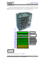
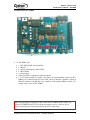
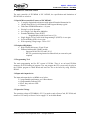
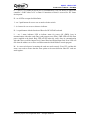
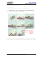
1
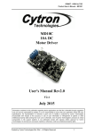
IFC-MB00
Interface Free Controller
Main Board
User’s Manual
V1.1
Apr 2008
Information contained in this publication regarding device applications and the like is intended through suggestion only and may
be superseded by updates. It is your responsibility to ensure that your application meets with your specifications. No
representation or warranty is given and no liability is assumed by Cytron Technologies Incorporated with respect to the accuracy
or use of such information, or infringement of patents or other intellectual property rights arising from such use or otherwise. Use
of Cytron Technologies’s products as critical components in life support systems is not authorized except with express written
approval by Cytron Technologies. No licenses are conveyed, implicitly or otherwise, under any intellectual property rights.
ROBOT . HEAD to TOE
Product User’s Manual – IFC-MB00
Index
1. Introduction and Overview
1
1.1 Introduction of Interface Free Controller
1
1.2 System Overview
2
2. Packaging List
3
2.1 Power Card (IFC-PC00)
3
2.2 Main Board (IFC-MB00)
4
3. Product Specification
5
3.1 Special Microcontroller Features of PIC18F2685
5
3.2 Peripheral Highlights
5
3.3 Programming Tool
5
3.4 Input and Output device
5
3.5 Operating Voltage
5
4. Board or Product Layout
6
4.1 Power Card (IFC-PC00)
6
4.2 Main Board (IFC-MB00)
8
5. Installation (hardware)
10
6. Installation (software)
17
6.1 MPLAB IDE Installation
17
6.2 MPLAB C18 Compiler Installation
24
6.3 Using MPLAB IDE
32
7. Getting Started
46
7.1 Basic Setup (IFC-PC00 + IFC-MB00)
47
7.2 Basic Setup with Control Panel (IFC-PC00 + IFC-MB00 + IFC-CP04)
51
8. Warranty
Created by Cytron Technologies Sdn. Bhd. – All Rights Reserved
56
ROBOT . HEAD to TOE
Product User’s Manual – IFC-MB00
1. INTRODUCTION AND OVERVIEW
1.1 Introduction of Interface Free Controller
IFC (Interface Free Controller) offer a new concept of developing microcontroller embedded
system and also robotics system. With IFC, no more frustration in determine hardware
interface and configuring peripheral in software. Checking few hundreds pages of data sheet
can be waved. With the concept of interfacing card, user may stack as many as 64 cards in a
system to get infinite combination of peripherals. The design aim is to offer 3 simple steps in
microcontroller system development – Configure card’s address, Stack IFC cards, Write
Program and Run!
Furthermore, with functions based software library, user save valuable time during software
development by concentrating on algorithm development. No more flipping or scrolling PIC
data sheet looking for ADCON0, T1CON or even TRISA. With just a programming hand
book, user may simply copy the header file, call comprehensive functions and it’s ready to
rock.
IFC come with a brain card (main controller) where the main program is loaded. There are
several cards available for robotics development such as control panel, 15A brush motor
driver, brushless motor controller, counter and digital input, output card and power card. This
document will focus on the main board card and power card. This card has been designed
with capabilities and features of:
• Industrial grade PCB.
• Every component is soldered properly and tested before board is shipped.
• On board UIC00A connector for ICSP loading of program.
• Come with PIC18F2685 MCU with 96K byte of program memory, 1K byte of
EEPROM and 3K byte of RAM
• 3 programmable push button, and 1 Reset button
• 8 programmable indicator LED
• Power, busy and error LED
• 1 buzzer
• 5V operation
• UART or RS232 communication port ready
• Running at 40MHz
• Template and sample source code is provided for MPLAB C18 compiler
This document explains the usage of IFC-MB00 (Main Board) and IFC-PC00 (Power Card).
Created by Cytron Technologies Sdn. Bhd. – All Rights Reserved
1
ROBOT . HEAD to TOE
Product User’s Manual – IFC-MB00
1.2 System Overview
With serial communication perception, IFC offer million of possibilities to develop
embedded system creatively and easily. In IFC, several cards are stacked to get a complete
embedded system. The minimum card requires is Power card and Main Board.
More cards
Control Panel Card
Digital Input Card
Output Card
More devices
Encoder, digital
sensor
Relays, etc
Brushless Motor Card
Brushless motors
Brushless Motor Card
Brushless motors
Brush Motor Card
Brush motor
Main Brain
Power card
Power and
communication
This document explains the method to use IFC-MB00.
Created by Cytron Technologies Sdn. Bhd. – All Rights Reserved
2
ROBOT . HEAD to TOE
Product User’s Manual – IFC-MB00
2. PACKAGING LIST
Please check the parts and components according to the packing list. If there are any parts
missing, please contact us at sales@cytron.com.my immediately.
2.1 Power Card (IFC-PC00)
1. 1 x IFC-PC00 with:
• 1 x toggle switch.
• 4 x Fuse.
• Female connector for every terminal.
• Other electronics components soldered on board.
Created by Cytron Technologies Sdn. Bhd. – All Rights Reserved
3
ROBOT . HEAD to TOE
Product User’s Manual – IFC-MB00
2.2 Main Board (IFC-MB00)
2. 1 x IFC-MB00 with:
• 1 x PIC18F2685 PIC microcontroller.
• 1 x Buzzer.
• 1 x Serial cable adaptor (female DB9).
• 1 x Box Header.
• 2 x mini jumper.
• Other electronics components soldered on board.
• 1 x CD which contained 3 folders. The folders are Documentation (consist of IFCMB00 User’s Manual and IFC-CP04 Card Library Functions), Installer (consist of
MPLAB Installer and MPLAB C18 compiler), and Program_MB00 (consist of 2
sample source codes for IFC-MB00).
Note: The packaging list included 2 cards, which are IFC-MB00 and IFC-PC00. It is
because IFC-MB00 needs IFC-PC00 for power supply, however, users are free to
choose to purchase the cards separately base on user’s requirement.
Created by Cytron Technologies Sdn. Bhd. – All Rights Reserved
4
ROBOT . HEAD to TOE
Product User’s Manual – IFC-MB00
3. PRODUCT SPECIFICATION
The main controller of IFC-MB00 is PIC 18F2685, the specification and limitations of
PIC18F2685 are as below:
3.1 Special Microcontroller Features of PIC18F2685:
• C compiler Optimized Architecture with optional Extended Instruction Set
• 100,000 Erase/Write Cycle Enhanced Flash Program Memory typical
• Flash/Data EEPROM Retention: > 40 years
• Priority Levels for Interrupts
• 8 x 8 Single-Cycle Hardware Multiplier
• Extended Watchdog Timer (WDT):
- Programmable period from 41 ms to 131s
• Single-Supply 5V In-Circuit Serial Programming™ (ICSP™) via two pins
• In-Circuit Debug (ICD) via two pins
• Wide operating voltage range: 2.0V to 5.5V
3.2 Peripheral Highlights:
• High-Current Sink/source 25 mA/25 mA
• Enhanced Addressable USART module:
- Supports RS-485, RS-232 and LIN 1.3
- RS-232 operation using internal oscillator block (no external crystal
required)
3.3 Programming Tool
The main programming tool for IFC system is UIC00A. There is an on board UIC00A
connector for ICSP loading of program. User can program the IFC system easily by plug in
the UIC00A program to Main Board and load hex file to the board by using software,
PICkit2.
3.4 Input and Output device
The input and output device on MB00 are as below:
• 3 programmable push button, and 1 Reset button
• 8 programmable indicator LED
• Power, busy and error LED
• 1 buzzer
3.5 Operation Voltage
The operation voltage of IFC-MB00 is 12V. User need to stack a Power Card, IFC-PC00, and
connect a 12V battery on Power Card to supply 12V to the Main Board.
Created by Cytron Technologies Sdn. Bhd. – All Rights Reserved
5
ROBOT . HEAD to TOE
Product User’s Manual – IFC-MB00
4. BOARD OR PRODUCT LAYOUT
4.1. Power Card (IFC-PC00)
A
B
C
M
L
D
K
E
E
F
J
Label
A
B
C
D
E
F
G
H
G
I
Function
Batt1 connector
Batt2 connector
Orientation marking
Fuse 3
Fuse 4
Side connector
Power Out connector
Label
H
I
J
K
L
M
Function
Power Out LED
Toggle switch
Status Indicator LED
Fuse 2
Fuse 1
Arrow
A – is Batt1 connector, a 12V battery should be connected here to supply 12V to the system.
Please ensure the polarity is correct when connect battery to the board.
B – is Batt2 connector, connect an additional 12V battery here will allow a supply of 24V
(Battery 1 + Battery 2) to the system. Please ensure the polarity is correct when connecting
battery to the board.
C – is the orientation marking on IFC-PC00. Every IFC card will have this orientation
marking, this is to help user in ensuring the cards are stack correctly.
D – is Fuse 3 (F3) which provide over current protection to 12V Power Out, when the fuse
blows, 12V Power Out to system will be terminated. The fuse value is 15A.
E – is Fuse 4 (F4) which provide over current protection to 24V Power Out, when the fuse
blows, 24V Power Out to system will be terminated. The fuse value is 15A.
Created by Cytron Technologies Sdn. Bhd. – All Rights Reserved
6
ROBOT . HEAD to TOE
Product User’s Manual – IFC-MB00
F – are side connector for stack card and communication between cards.
G – are two Power Out connector for user to use as power supply for other output device,
example: brushless motor.
H – are 2 Power Out LED to indicate the availability of the Power Out supply to other IFC
cards.
I – is a toggle switch for user to ON/OFF the main power supply.
J – are 2 status indicator LED to indicate status for power supply. 12V LED will turn ON
when Batt1 is connected with a 12V battery. Both of 12V and 24V LED will turn ON when
Batt1 and Batt2 are connected with 12V battery.
K – is Fuse 2 (F2) which provide over current protection to 24V power supply, when the fuse
blows, 24V power supply to system will be terminated. The fuse value is 10A.
L – is Fuse 1 (F1) which provide over current protection to 12V power supply, when the fuse
blows, 12V power supply to system will be terminated. The fuse value is 5A.
M – is an arrow to help user in ensuring the cards are stack correctly. Every IFC card has this
arrow; user needs to ensure that the arrow points to the same direction when IFC cards are
stack together.
Created by Cytron Technologies Sdn. Bhd. – All Rights Reserved
7
ROBOT . HEAD to TOE
Product User’s Manual – IFC-MB00
4.2. Main Board (IFC-MB00)
B
A
C
D
E
M
F
F
L
Label
A
B
C
D
E
F
G
K J
Function
5V regulator
Serial cable adaptor (female DB9)
PIC18F2685
Box Header for UIC00A
Orientation marking
Side connector
Header Pin for UART communication
selection
I
H
Label
H
I
J
K
L
M
G
Function
Output LED
Push buttons
Buzzer
Reset Button
Status Indicator LED
Arrow
A – is a 5V voltage regulator.
B – is a Serial port (RS232) which allow user to connect the controller’s UART to PC.
C – is PIC18F2685 which is used as main controller for the system.
D – is a 2x5 box header for UIC00A, USB ICSP PIC Programmer.
E – is the orientation marking on IFC-MB00. Every IFC card will have this orientation
marking, this is to help user in ensuring the cards are stack correctly.
F – are side connector for stack card and communication between cards.
Created by Cytron Technologies Sdn. Bhd. – All Rights Reserved
8
ROBOT . HEAD to TOE
Product User’s Manual – IFC-MB00
G – 2 sets of 3 x 1 header pin for Rx and Tx communication. User can choose to connect the
controller’s UART either to PC or Board. Connection to Board is reserved for IFC future
development.
H – are 8 LEDs as output for Main Brain.
I – are 3 push buttons for user to use as mode selection switch.
J – is a buzzer for user to use as alarm or indicator.
K – is a push button with the function of Reset for PIC18F2685 on board.
L – are 3 status indicator LED to indicate status for power ON (PWR), busy in
communication with other cards (Busy) and program error (Error). PWR LED will ON when
power supplied to the board. Busy LED will ON when the card is busy in communication
with other slave card like Output Card, Control Panel and Digital Input card. Error LED will
ON when the address set on slave card did not match with the address in main program.
M – is a arrow to help user in ensuring the cards are stack correctly. Every IFC card has this
arrow; user needs to ensure that the arrow points to the same direction when IFC cards are
stack together.
Created by Cytron Technologies Sdn. Bhd. – All Rights Reserved
9
ROBOT . HEAD to TOE
Product User’s Manual – IFC-MB00
5. INSTALLATION (HARDWARE)
i) Main power supply:
• 1 x 12V battery.
• Provide power for circuit, relays, sensors and signal for brush motor.
• If brushless motor is used, 2 x 12V batteries must be connected to provide 24V.
ii) How to connect the wire to battery connector (3961):
1
2
3
4
5
6
7
8
Ensure the iron
pins are fully
inserted to the
connector
The red wire connected to VCC (+) of battery while the black wire connected to GND (-) of
the battery. Please make sure the polarity is correct when connect the wire to the connector.
Created by Cytron Technologies Sdn. Bhd. – All Rights Reserved
10
ROBOT . HEAD to TOE
Product User’s Manual – IFC-MB00
iii) Connect battery to Power Card, IFC-PC00.
Connect 1 x 12V
battery to supply
operating voltage to
IFC. Ensure the
polarity is correct.
If 24V is needed in
the system, connect
2 x 12V batteries to
PC00. Ensure the
polarity is correct.
iv) Stacking IFC cards together.
IFC-MB00 stacked on IFC-PC00
Created by Cytron Technologies Sdn. Bhd. – All Rights Reserved
11
ROBOT . HEAD to TOE
Product User’s Manual – IFC-MB00
v) Ensure every card is being stack properly in correct orientation.
Ensure the arrow
points to the same
direction
Ensure the
orientation
marking at the
same side.
Cautions: Please ensure that every card is being stacked properly in correct orientation.
Whole IFC system will be damaged if one of the cards is being stacked wrongly when it
is powered up.
Created by Cytron Technologies Sdn. Bhd. – All Rights Reserved
12
ROBOT . HEAD to TOE
Product User’s Manual – IFC-MB00
Besides stack every card in correct orientation, user must also require to ensure all card pins
are not shifted when stacking. Figures show the example of stacking cards in proper location
and example of stacking cards with shifted pins.
Ensure that all card
pins are not shifted
when stacking.
Examples of
stacking cards with
shifted pins. Please
AVOID this!
Created by Cytron Technologies Sdn. Bhd. – All Rights Reserved
13
ROBOT . HEAD to TOE
Product User’s Manual – IFC-MB00
Ensure that all card
pins are not shifted
when stacking.
Examples of
stacking cards with
shifted pins. Please
AVOID this!
Cautions: Please ensure that all card pins are not shifted when stacking. IFC system will
NOT function if the pins are shifted.
Created by Cytron Technologies Sdn. Bhd. – All Rights Reserved
14
ROBOT . HEAD to TOE
Product User’s Manual – IFC-MB00
Next, please turn ON the power on Power Card by pushing the toggle switch to “ON” label,
the PWR LED of IFC-MB00 and IFC-PC00 will turn ON as shown in Figure.
PWR LED on
IFC - MB00
12V LED on
IFC - PC00
Created by Cytron Technologies Sdn. Bhd. – All Rights Reserved
15
ROBOT . HEAD to TOE
Product User’s Manual – IFC-MB00
To open the cards, user can use the IFC card’s opener to open the stacked cards. Figure
shows the method to open cards with the opener. Please ensure the power is OFF before
inserting or removing IFC card.
1
2
3
Caution: Please use the opener to open IFC cards to avoid damage to pins or cards.
Created by Cytron Technologies Sdn. Bhd. – All Rights Reserved
16
ROBOT . HEAD to TOE
Product User’s Manual – IFC-MB00
6. INSTALLATION (SOFTWARE)
A program editor, C compiler and UIC00A software is required to be installed in
order for user to write program, compile it and further loading program to IFC main board.
User is recommended to use MPLAB IDE as source code editor and MPLAB C18 as C
compiler. Both this software is from Microchip and it is provided freely to download. This
section will explain the method to install these software and next section will briefly discuss
on method to use it. As for the installation of UIC00A software, please refer to UIC00A
User’s Manual.
6.1 MPLAB IDE Installation
MPLAB Integrated Development Environment (IDE) is a comprehensive editor,
project manager and design desktop for application development of embedded designs using
Microchip PICmicro and dsPIC microcontrollers. It is a free product of Microchip Inc. and is
an effort to make source code development as smooth and comprehensive as possible. It is
called an Integrated Development Environment, or IDE, because it provides a single
integrated “environment” to develop code for embedded microcontrollers. MPLAB IDE
provides a good platform for other compiler language tools to be integrated. MPLAB C17,
MPLAB C18 and MPLAB C30 from microchip provide fully integrated, optimized code. To
install MPLAB IDE, simply open the folder of “IFC\Installer\MPLAB_v8” in the IFC-MB00
CD. Current version of MPLAB IDE is 8.00. For the latest version of MPLAB IDE, please
download from Microchip website, www.microchip.com. Please install MPLAB IDE
according to the following steps.
1. Please double click on the Setup Launcher to install MPLAB V8.00.
Created by Cytron Technologies Sdn. Bhd. – All Rights Reserved
17
ROBOT . HEAD to TOE
Product User’s Manual – IFC-MB00
2. The InstallShield Wizard will pop out.
3. After all the directions shown in the welcome note (as in following diagram) is done,
please click Next> for next step.
Created by Cytron Technologies Sdn. Bhd. – All Rights Reserved
18
ROBOT . HEAD to TOE
Product User’s Manual – IFC-MB00
4. Please select I accept the terms of the license agreement if it is not selected in the
diagram below, and click Next> after this.
5. Please select Complete for the setup type to install all program features, and click
Next> to next step.
Created by Cytron Technologies Sdn. Bhd. – All Rights Reserved
19
ROBOT . HEAD to TOE
Product User’s Manual – IFC-MB00
6. In the Choose Destination Location, user is recommended to use the default
destination folder, which is C:\Program Files\Microchip\ or user is also free to select
the other destination folder by using the Browse… button to browse to the desired
destination folder. After that, click Next> for next step.
7. Please select I accept the terms of the license agreement if it is not selected in the
diagram below, and click Next> after this.
Created by Cytron Technologies Sdn. Bhd. – All Rights Reserved
20
ROBOT . HEAD to TOE
Product User’s Manual – IFC-MB00
8. Please click Next> for the diagram below.
9. Please wait for awhile for the installation process shown in diagram below.
Created by Cytron Technologies Sdn. Bhd. – All Rights Reserved
21
ROBOT . HEAD to TOE
Product User’s Manual – IFC-MB00
10. A window will pop out if there are any program that did not close at the beginning of
the installation, user is recommended to close the entire unnecessary program and
click Retry to proceed on the installation. User may also click on Ignore if you need to
run the other program concurrently. For this example, Ignore is clicked.
11. Please wait for the installation process to be completed.
Created by Cytron Technologies Sdn. Bhd. – All Rights Reserved
22
ROBOT . HEAD to TOE
Product User’s Manual – IFC-MB00
12. A window for Installing PICC-Lite will pop out, please click OK to proceed.
13. Please click Cancel to exit from Installing HI-TECH PICC-Lite since this function
will not be use in IFC. Anyway, user may also install HI-TECH PICC-Lite if it is
needed.
Created by Cytron Technologies Sdn. Bhd. – All Rights Reserved
23
ROBOT . HEAD to TOE
Product User’s Manual – IFC-MB00
14. Please click Yes for the pop out window to cancel the setup of HI-TECH PICC-Lite.
15. The installation of MPLAB V8.00 is completed. Please click Finish to exit. User may
need to restart the computer just after the installation or restart later.
Created by Cytron Technologies Sdn. Bhd. – All Rights Reserved
24
ROBOT . HEAD to TOE
Product User’s Manual – IFC-MB00
6.2 MPLAB C18 Compiler Installation
The MPLAB® C18 compiler is a full-featured ANSI compliant C compiler for the
PIC18 family of PICmicro® 8-bit MCUs. Microchip offer free MPLAB C18 compiler for
student with no limitation of code size and PIC type; the only drawback is the code
optimization is disabled. For details description of MPLAB C18, please refer to MPLAB C18
User’s Manual. Following diagrams show the installation guide of Student Version of
MPLAB C18 compiler. To start MPLAB C18 installation, simply open the folder of
“IFC\Installer\MPLAB_C18” in the IFC-MB00 CD. MPLAB IDE needs to be installed
before installation of MPLAB C18. Please install MPLAB C18 according to following steps.
1. Please double click on the application file for MPLAB-C18-StudentEdition-v3_15a to
start the installation.
Created by Cytron Technologies Sdn. Bhd. – All Rights Reserved
25
ROBOT . HEAD to TOE
Product User’s Manual – IFC-MB00
2. An Initializing Wizard that looks like the diagram below will pop out
3. After that, there will be a welcome screen displays the version number of MPLAB
C18 that the setup program will install. Please click Next> to proceed.
Created by Cytron Technologies Sdn. Bhd. – All Rights Reserved
26
ROBOT . HEAD to TOE
Product User’s Manual – IFC-MB00
4. For License Agreement, please select I Accept if it is not selected in the diagram
below, and click Next> after this.
5. In the Select Installation Directory, user is recommended to use the default
installation directory, which is C:\MCC18 or user is also free to select the other
installation directory by using the Browse… button to browse to the desired
destination folder. After that, click Next> for next step.
Created by Cytron Technologies Sdn. Bhd. – All Rights Reserved
27
ROBOT . HEAD to TOE
Product User’s Manual – IFC-MB00
6. User can choose the components to be installed by checking the appropriate box in
Select Components window. Please refer to MPLAB-C18-Getting-Started document
in the CD for detailed description of the available components.
7. The Configuration Options below allows users to select a particular set of desired
environment variable configuration options for their system. Please refer to MPLABC18-Getting-Started document in the CD for detailed description of the available
configuration options. In this example, all the options are selected. Please click Next>
to continue.
Created by Cytron Technologies Sdn. Bhd. – All Rights Reserved
28
ROBOT . HEAD to TOE
Product User’s Manual – IFC-MB00
8. There is another Configuration Options which allows users to select a particular set of
desired MPLAB IDE configuration options for their system. Please refer to MPLABC18-Getting-Started document in the CD for detailed description of the available
configuration options. In this example, all the options are selected. Please click Next>
to continue.
9. Please click Next> for the diagram below to start installation after all the setting done.
Created by Cytron Technologies Sdn. Bhd. – All Rights Reserved
29
ROBOT . HEAD to TOE
Product User’s Manual – IFC-MB00
10. Please wait for awhile for the installation process shown in diagram below.
11. After the installation completed, a diagram as below will be shown, user can select the
release notes that wish to read, in this example, the release notes for MPLAB C18 is
being selected. Please click Finish> to exit installation.
Created by Cytron Technologies Sdn. Bhd. – All Rights Reserved
30
ROBOT . HEAD to TOE
Product User’s Manual – IFC-MB00
12. The release notes MPLAB C18 is being shown after the installation process since it
was being selected in the last step.
Created by Cytron Technologies Sdn. Bhd. – All Rights Reserved
31
ROBOT . HEAD to TOE
Product User’s Manual – IFC-MB00
6.3 Using MPLAB IDE
To start MPLAB IDE, please follow the step below:
1. Double click on the icon installed on the desktop after installation or select
Start>Programs>Microchip> MPLAB IDE v8.00>MPLAB IDE. A screen will
display the MPLAB IDE logo followed by the MPLAB IDE desktop as in diagram
below.
Created by Cytron Technologies Sdn. Bhd. – All Rights Reserved
32
ROBOT . HEAD to TOE
Product User’s Manual – IFC-MB00
2. The capabilities of MPLAB IDE vary according to which device is selected. Device
selection should be completed before starting a project. In this project, user should
select PIC18F2685 as the device. Please go to Configure>Select Device to choose the
device as shown in diagram below.
3. The “lights” indicate which MPLAB IDE components support this device.
• A green light indicates full support.
• A yellow light indicates minimal support for an upcoming part that might not
be fully supported in this release by the particular MPLAB IDE component.
• Components with a yellow light instead of a green light are often intended for
early adopters of new parts who need quick support and understand that some
operations or functions may not be available.
• A red light indicates no support for this device. Support may be forthcoming
or inappropriate for the tool, e.g., dsPIC devices cannot be supported on
MPLAB ICE 2000.
Created by Cytron Technologies Sdn. Bhd. – All Rights Reserved
33
ROBOT . HEAD to TOE
Product User’s Manual – IFC-MB00
4. The next step is to create a project using the Project Wizard. A project is the way the
files are organized to be compiled and assembled. We Choose Project>Project
Wizard. From the Welcome dialog, click on Next to proceed. The next dialog (Step
One) allows you to select the device, which we’ve already done. Make sure that it
says PIC18F2685. If it does not, select the PIC18F2685 from the drop down menu.
Click Next>.
Created by Cytron Technologies Sdn. Bhd. – All Rights Reserved
34
ROBOT . HEAD to TOE
Product User’s Manual – IFC-MB00
5. The next step of the Project Wizard is sets up the language tools that are used with
this project. Select “Microchip C18 Toolsuite” in the Active Toolsuite list box. Then
“MPASM”, “MPLINK”, “MPLAB” and “MPLIB” should be visible in the Toolsuite
Contents box. Click on each one to see its location. If MPLAB IDE was installed into
the default directory;
MPASM assembler executable will be:
C:\MCC18\mpasm\mpasmwin.exe
MPLINK Object linker executable will be:
C:\MCC18\bin\mplink.exe
MPLAB C18 C compiler executable will be:
C:\MCC18\bin\mcc18.exe
MPLIB librarian executable will be:
C:\MCC18\bin\mplib.exe
If these do not show up correctly, use the browse button to set them to the proper files
in the MPLAB IDE subfolders. When you are finished, click Next.
Created by Cytron Technologies Sdn. Bhd. – All Rights Reserved
35
ROBOT . HEAD to TOE
Product User’s Manual – IFC-MB00
6. Step three of the project wizard allows user to create new project file. For an example,
a subfolder named Program_MB00 was first created under IFC folder, then by using
the Browse… button, browse to the subfolder, Program_MB00. Project named
“IFC_MB00” can be created by typing the project name in the column for “File
name”, and click Save.
7. Diagram below shown the Project “IFC_MB00” had been created and the directory.
Click Next>.
Created by Cytron Technologies Sdn. Bhd. – All Rights Reserved
36
ROBOT . HEAD to TOE
Product User’s Manual – IFC-MB00
8. Step four of the project wizard allow user to add existing file to the project, however,
for this project, the files will be added in step later. Please click Next> to proceed.
9. A summary will be shown at the end of project wizard, all the project parameters are
shown. Please click Finish to exit from project wizard.
Created by Cytron Technologies Sdn. Bhd. – All Rights Reserved
37
ROBOT . HEAD to TOE
Product User’s Manual – IFC-MB00
10. After pressing the Finish button, review the Project Window on the MPLAB IDE
desktop. It should look like the diagram below. If the Project Window is not open,
please select View>Project.
11. It is recommended for user to copy all C file, object file and header file from the CD
provided to the specific project folder open for IFC-MB00 in step 6, which is
Program_MB00. It is because all C file, object file and header file should be place in
the same folder with the project file. User should follow the subsequent steps to add
files in the project created.
12. To add file in Source Files, right click on the Source Files, then click on Add Files…,
diagram below shown the example for add file to Source Files.
Created by Cytron Technologies Sdn. Bhd. – All Rights Reserved
38
ROBOT . HEAD to TOE
Product User’s Manual – IFC-MB00
13. After clicking on Add Files…, a window pop out, do make sure the Files of type is All
Source Files(*.asm;*.c), then browse to the subfolder named Program_MB00 to add
in “Sample1.c”. For this example, the “Sample1.c” is located in D:\IFC\
Program_MB00. User can select the file, “Sample1.c”, and click open to add the file.
14. After the “Sample1.c” file is added under Source Files, the MPLAB IDE will look
like the diagram below.
Created by Cytron Technologies Sdn. Bhd. – All Rights Reserved
39
ROBOT . HEAD to TOE
Product User’s Manual – IFC-MB00
15. To add header file in the project, right click on the Header Files, then click on Add
Files…, diagram below shown the example for add file to Header Files.
16. After clicking on Add Files…, a window pop out, do make sure the Files of type is
Header Files(*.h;*.inc), browse to the subfolder named Program_MB00 to add in
“iic.h”. For this example, the “iic.h” is located in D:\IFC\ Program_MB00. Select the
file “iic.h”, and click open to add the file.
Created by Cytron Technologies Sdn. Bhd. – All Rights Reserved
40
ROBOT . HEAD to TOE
Product User’s Manual – IFC-MB00
17. After the “iic.h” file is added under Header Files, the MPLAB IDE will look like the
diagram below.
18. User may repeat the similar steps to add object file in the project. First, right click on
the Object Files, then click on Add Files…, diagram below shown the example for add
file to Object Files.
Created by Cytron Technologies Sdn. Bhd. – All Rights Reserved
41
ROBOT . HEAD to TOE
Product User’s Manual – IFC-MB00
19. After clicking on Add Files…, a window pop out, do make sure the Files of type is
Object Files(*.o), browse to the subfolder named Program_MB00 to add in “iic.o”.
For this example, the “iic.o” is located in D:\IFC\ Program_MB00. Select the file,
“iic.o”, and click open to add the file.
20. After the “iic.o” file is added under Object Files, the MPLAB IDE will look like the
diagram below.
Created by Cytron Technologies Sdn. Bhd. – All Rights Reserved
42
ROBOT . HEAD to TOE
Product User’s Manual – IFC-MB00
21. User also needs to add another file, 18f2685.lkr, under Linker Script. If user did not
change the default directory during installation in chapter 6.2, user should be able to
find 18f2685.lkr in C:\MCC18\lkr. Diagram below shows the example step to add file
in Linker Script, it is similar with the steps to add C file, object file and header file.
22. After selecting 18f2685.lkr, click open, then the file will be added under Linker
Script.
Created by Cytron Technologies Sdn. Bhd. – All Rights Reserved
43
ROBOT . HEAD to TOE
Product User’s Manual – IFC-MB00
23. After added all the necessary files, user can open Sample1.c file in this workspace and
try to compile it. Diagram below shown opened Sample1.c file.
24. To compile, user can go Project>Build All as shown in diagram below.
Created by Cytron Technologies Sdn. Bhd. – All Rights Reserved
44
ROBOT . HEAD to TOE
Product User’s Manual – IFC-MB00
25. After build success, a message BUILD SUCCEEDED will appear in output window
like shown in diagram below.
26. Please refer chapter 7 - Getting Started for modifying program and other setup for
using IFC MB00.
Created by Cytron Technologies Sdn. Bhd. – All Rights Reserved
45
ROBOT . HEAD to TOE
Product User’s Manual – IFC-MB00
7. GETTING STARTED
IFC is being design with the aim of 3 simple steps. Configure card address, Stack it, Load
program and run. There must be at least a power card (IFC-PC00) and a main board (IFCMB00) for this system to function. Since IFC offer many possibilities to create your own
system, this section will show several examples of operating it. There should be only one
power card and one main board in IFC system; however, there is not limitation (maximum 64
cards) for the amount of slave cards.
1st step: Address
- Configure Card’s address
2nd step: Stacking
- Stack the card/s
- Connect the necessary battery
- Connect necessary sensor or motor
- Turn it ON
3rd step: Program
- Include the necessary header and
object file/s
- Write program using template
given
- Call necessary function referring to
Program Reference Notes
- Compile and Load Program
through UIC00A
There are 2 basic setups in this chapter for IFC-MB00. First setup includes 2 cards, IFCPC00 and IFC-MB00, and second setup includes one extra card, which is IFC-PC04. Please
refer to following section of this chapter for setup details.
Created by Cytron Technologies Sdn. Bhd. – All Rights Reserved
46
ROBOT . HEAD to TOE
Product User’s Manual – IFC-MB00
7.1 Basic setup (IFC-PC00 + IFC-MB00)
This is the basic and minimum setup for IFC to function. Though without other card, this
basic setup can still perform some task such as reading switch, LED blinking pattern,
controlling buzzer and RS232 communication. Following steps show the installation of this
system and method to operate it.
a. 1st step should be configuring card address; however, since this is the minimum
system, no configuration on card address is necessary.
b. 2nd step is to stack both these cards. Power card (IFC-PC00) should be at the bottom,
while Main board (IFC-MB00) at the top or 2nd layer as shown in following figure.
Ensure the arrow
points to the same
direction
Ensure the
orientation
marking at the
same side.
Created by Cytron Technologies Sdn. Bhd. – All Rights Reserved
47
ROBOT . HEAD to TOE
Product User’s Manual – IFC-MB00
c. Connect the battery to Power card as shown; please ensure the polarity is correct.
Connect 1 x 12V
battery to supply
operating voltage to
IFC. Ensure the
polarity is correct.
If 24V is needed in
the system, connect
2 x 12V batteries to
PC00. Ensure the
polarity is correct.
d. Turn on the IFC power by pushing the toggle switch to “ON”. There should be at least
2 LED (PWR LED on Main Brain and 12V LED on Power Card) light up as show.
PWR LED on
IFC - MB00
12V LED on
IFC - PC00
e. By default, IFC-MB00 is loaded with a demo firmware which will show LED
blinking when it is powered up.
Created by Cytron Technologies Sdn. Bhd. – All Rights Reserved
48
ROBOT . HEAD to TOE
Product User’s Manual – IFC-MB00
f. 3rd step is to write program and load it. IFC comes with comprehensive function to
save program development time. Functions library will come with the interfacing card
in the form of header file (*.h) and object file (*.o). In order to call these functions,
particular header file and object file must be included under a project.
g. Open MPLAB IDE (please ensure, MPLAB C18 is being installed). User can follow
the step in chapter 6.2 Using MPLAB IDE to open project named “IFC_MB00” for
IFC Main Brain. Please note that the header file (iic.h) and object file (iic.o) for IFCMB00 has to be included in the project. If user did not use the provided sample source
code, “Sample1.c”, user also needs to include card’s header file at the beginning of
the program. Figure shows the example to include header file, object file and card’s
header file.
h. For those wanted to understand the program, please refer to c file named “Sample1.c”
which is provided with this card.
i. After completed the steps in chapter 6.2, a hex file for the sample project should be
generated. Connect UIC00A IDC connector to IFC-MB00A as shown. The hex file
generated is named “IFC_MB00.hex”. Please note that Hex file generated from
MPLAB IDE will be named according to project name, not C file name or header file
name.
Created by Cytron Technologies Sdn. Bhd. – All Rights Reserved
49
ROBOT . HEAD to TOE
Product User’s Manual – IFC-MB00
Connector from
UIC00A programmer
j. Power up IFC system if it is OFF. Load the hex file generated to IFC main board
using UIC00A (refer to UIC00A User’s Manual for details). Check the result of
program, debug/modify if necessary.
k. User is free to modify the sample program to play with the IFC-MB00. After
modifying the sample program, user can follow step No.24 in chapter 6.2 to compile
and generate hex file. Hex file can be loaded again to IFC main board and check the
result of program.
l. To remove a card from IFC system, the power should be switched OFF.
m. Please use proper tool to remove the card. User may refer last section in chapter 5.0
Installation (hardware) for the method to open card with provided IFC card opener.
Created by Cytron Technologies Sdn. Bhd. – All Rights Reserved
50
ROBOT . HEAD to TOE
Product User’s Manual – IFC-MB00
7.2 Basic Setup with Control Panel (IFC-PC00 + IFC-MB00 + IFC-CP04)
Adding a control panel which comes with a 2 x16 character LCD and 4 programmable push
buttons will offer more interesting demonstration. Following steps show the installation of
this system and method to operate it.
a. 1st step, configure the address of card. Control Panel has a mini jumper to configure
address. It should be set to “CP1” (Upper side) if sample source code is being used.
b. 2nd step is to stack all three cards together. Power card (IFC-PC00) should be at the
bottom, while Main board (IFC-MB00) at 2nd layer and Control Panel (IFC-CP04) at
top layer as shown in following figure.
Ensure the arrow
points to the same
direction
Ensure the
orientation
marking at the
same side.
Created by Cytron Technologies Sdn. Bhd. – All Rights Reserved
51
ROBOT . HEAD to TOE
Product User’s Manual – IFC-MB00
c. Connect the battery to Power card as shown; please ensure the polarity is correct.
Connect 1 x 12V
battery to supply
operating voltage to
IFC. Ensure the
polarity is correct.
If 24V is needed in
the system, connect
2 x 12V batteries to
PC00. Ensure the
polarity is correct.
d. Turn ON the IFC power by pushing the toggle switch to “ON”. There should be at
least 3 LED (12V LED on Power Card, PWR LED on Main Brain and PWR LED on
Control Panel) light up as show.
PWR LED on
IFC - CP04
PWR LED on
IFC - MB00
12V LED on
IFC - PC00
Created by Cytron Technologies Sdn. Bhd. – All Rights Reserved
52
ROBOT . HEAD to TOE
Product User’s Manual – IFC-MB00
e. 3rd step is to write program and load it. IFC comes with comprehensive function to
save program development time. Functions library will come with the interfacing card
in the form of header file (*.h) and object file (*.o). In order to call these functions,
particular header file and object file must be included under a project.
f. Open MPLAB IDE (please ensure, MPLAB C18 is being installed). User can follow
the step in chapter 6.2 Using MPLAB IDE to open project named “IFC_CP” for IFC
Control Panel. Please note that the header file (iic.h and iic_cp.h) and object file (iic.o
and iic_cp.o) for IFC-MB00 and IFC-CP04 have to be included in the project. If user
did not use the provided sample source code, “Sample2.c”, user also needs to include
card’s header file at the beginning of the program. Figure shows the example to
include header file, object file and card’s header file.
g. For those wanted to understand the program, please refer to c file named “Sample2.c”
which is provided with this card.
Created by Cytron Technologies Sdn. Bhd. – All Rights Reserved
53
ROBOT . HEAD to TOE
Product User’s Manual – IFC-MB00
h. Compile this project to generate hex file. Connect UIC00A IDC connector to IFCMB00 as show. The hex file generated is named “IFC_CP.hex”. Please note that Hex
file generated from MPLAB IDE will be named according to project name, not C file
name or header file name.
Connector from
UIC00A programmer
i. However, user may also add the “Sample2.c”, “iic_cp.h” and “iic_cp.o” to project
opened in chapter 7.0 without creating a new project for Control Panel.
j. Load the hex file generated to UIC00A using PICkit2 window (refer to UIC00A
User’s Manual for details). Power up IFC system if it is OFF.
k. This sample project will print message at LCD on Control panel after reset. The
message print after reset are:
Welcome!
IFC User
l. There are also 4 modes for user to select in program “Sample2.c”. User can select
mode by pressing push button on IFC-CP04. Each time after selecting the mode, user
needs to press reset to exit if other mode is require to be tested. The modes are:
Mode
Push Button
1
SW1
2
SW2
3
SW3
4
SW4
Function
Display Thank You note to IFC user,
LED No.1 on IFC-MB00 will turn ON
and buzzer on MB00 will ‘beep’ for 1
time.
Display Decimal Number 123456 on
LCD, LED No.2 on IFC-MB00 will
turn ON and buzzer on MB00 will
‘beep’ for 2 times.
Display Character ‘A’ on LCD, LED
No.3 on IFC-MB00 will turn ON and
buzzer on MB00 will ‘beep’ for 3 times.
Display Binary Number 10101010 on
LCD, LED No.4 on IFC-MB00 will
turn ON and buzzer on MB00 will
‘beep’ for 4 times.
Created by Cytron Technologies Sdn. Bhd. – All Rights Reserved
54
ROBOT . HEAD to TOE
Product User’s Manual – IFC-MB00
m. Please refer the comment in source code for the details of mode.
n. To remove a card from IFC system, the power should be switched OFF.
o. Please use proper tool to remove the card. User may refer last section in chapter 5.0
Installation (hardware) for the method to open card with provided IFC card opener.
Note 1: User can refer to IFC-CP04 Card Library Function for the program function
list. It will help user in writing program for IFC-CP04.
Note 2: There is also a Template file included in the CD, user can find the template in
folder “IFC/Program_MB00”. The Template will help user to start basic program
development for IFC system.
Note 3: Each time opening a new project for IFC, user needs to add ALL header files
and object files for all related IFC cards used. User also needs to include ALL cards’
header file at the beginning of the program. Please refer sample source code for the
example to include card h file.
Created by Cytron Technologies Sdn. Bhd. – All Rights Reserved
55
ROBOT . HEAD to TOE
Product User’s Manual – IFC-MB00
8. WARRANTY
¾
¾
¾
¾
Product warranty is valid for 6 months.
Warranty only applies to manufacturing defect.
Damage caused by misuse is not covered under warranty.
Warranty does not cover freight cost for both ways.
Prepared by
Cytron Technologies Sdn. Bhd.
19, Jalan Kebudayaan 1A,
Taman Universiti,
81300 Skudai,
Johor, Malaysia.
Tel:
Fax:
+607-521 3178
+607-521 1861
URL: www.cytron.com.my
Email: support@cytron.com.my
sales@cytron.com.my
Created by Cytron Technologies Sdn. Bhd. – All Rights Reserved
56