1
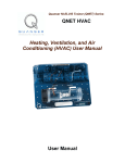
© 2011 Quanser Inc., All rights reserved.
Quanser Inc.
119 Spy Court
Markham, Ontario
L3R 5H6
Canada
info@quanser.com
Phone: 1-905-940-3575
Fax: 1-905-940-3576
Printed in Markham, Ontario.
For more information on the solutions Quanser Inc. offers, please visit the web site at:
http://www.quanser.com
This document and the software described in it are provided subject to a license agreement. Neither the software nor this document may be
used or copied except as specified under the terms of that license agreement. All rights are reserved and no part may be reproduced, stored in
a retrieval system or transmitted in any form or by any means, electronic, mechanical, photocopying, recording, or otherwise, without the prior
written permission of Quanser Inc.
Acknowledgements
Quanser, Inc. would like to thank the following contributors:
Dr. Hakan Gurocak, Washington State University Vancouver, USA, for his help to include embedded outcomes assessment, and
Dr. K. J. Åström, Lund University, Lund, Sweden for his immense contributions to the curriculum content.
QNET HVACT Workbook - Student Version
2
Contents
1
Introduction
4
2
On-Off Control
2.1
Background
2.2
On-Off Control Virtual Instrument
2.3
Startup [10 min]
2.4
Lab 1: Relay Control [30 min]
2.5
Lab 2: Modeling [30 min]
5
5
6
7
7
8
3
PI Control
3.1
Background
3.2
Speed Control Virtual Instrument
3.3
Startup [10 min]
3.4
Lab 1: Qualitative PI Control [30 min]
3.5
Lab 2: Saturation and Windup [30 min]
3.6
Lab 3: Set-Point Weight [20 min]
3.7
Lab 4: PI Control according to Specifications [30 min]
9
9
10
10
11
11
12
12
4
System Requirements
4.1
Overview of Files
4.2
On-Off Control VI
4.3
PI Control VI
14
14
15
17
5
Lab Report
5.1
Template for Content (On-Off Control)
5.2
Template for Content (PI Control)
5.3
Tips for Report Format
19
19
20
21
QNET HVACT Workbook - Student Version
v 1.0
1
INTRODUCTION
The QNET-012: heating and ventilation trainer (HVACT) is shown in Figure 1.1. The system consists of a plexiglass
duct, with a heater in one end and a blower in the other end. The heater is a halogen lamp and the blower is a
variable-speed fan. There is a thermistor sensor placed inside the duct to measure the temperature of the chamber
and another thermistor sensor outside the chamber to measure the room temperature.
Figure 1.1: QNET heating and ventilation trainer (HVACT)
The temperature measured at the thermistor inside the chamber is to be controlled using the heater voltage while the
fan is ran at a constant speed. Heat is transferred to the thermistor by radiation from the heater and by convection
from the air stream. Radiative heat transfer is highly nonlinear and it is therefore difficult to model the system by first
principles. As a result, empirical tuning will be used to control the system. This heat transfer plant is very similar to
the systems that are used to control wafer temperature in semiconductor manufacturing.
There are two experiments: on-off control and PI control. The experiments can be performed independently.
Topics Covered
• On-off control
• Modeling
• PI control
• Integrator windup
• Set-point weight
Prerequisites
In order to successfully carry out this laboratory, the user should be familiar with the following:
• Transfer function fundamentals, e.g., obtaining a transfer function from a differential equation.
• Using LabVIEWr to run VIs.
QNET HVACT Workbook - Student Version
4
2
ON-OFF CONTROL
2.1 Background
2.1.1 Relay Control
On-off control or relay feedback is one of the simplest control strategies. The heater is switched on when the
temperature is lower than the desired value, and the heater is switched off when the temperature is higher than the
desired value. To avoid rapid switches it is common to introduce a hysteresis in the relay switch. A block diagram
of a system with relay feedback is shown in Figure 2.1.
Figure 2.1: Block diagram of the heater system with relay feedback
The error, variable e in Figure 2.1, is the difference between the reference temperature, Tr , and the actual chamber
temperature, Tc . The on-off controller is implemented using a relay switch with hysteresis, as shown in Figure
2.2. The heater actuator is represented by a saturation block and the chamber plant is represented by the transfer
function P (s).
Figure 2.2: Input and output relation for an on-off controller with hysteresis
The hysteresis width, ∆Th in Figure 2.2, has to be chosen such that a large measurement noise does not generate
QNET HVACT Workbook - Student Version
v 1.0
any unintentional switches. As depicted in Figure 2.2, the output control signal voltage of the on-off controller can
be adjusted using a mean or offset, Vh,off , and an amplitude, Vh,amp .
In the experiment, the behavior of the heater system will be investigated for different values of controller parameters.
More specifically, the control signal and the measured temperature will be observed.
2.1.2 Modeling
The on-off control input and the measured temperature output from the experiment have an interesting property that
makes it possible to find a simple model for the process. The temperature response is a ramp due a voltage step
therefore the temperature is the integral of the voltage. Under certain conditions, the process can be modeled by
the simple transfer function
Kv
P (s) =
(2.1)
s
where the parameter Kv is the slope of the ramp.
2.2 On-Off Control Virtual Instrument
Tracking a reference temperature using a relay control is first examined in this laboratory. Then, when commanding
a fixed refernce, the system can be modeled. The LabVIEW virtual instrument for on-off temperature control is
shown in Figure 2.3.
Figure 2.3: Virtual instrument for on-off heater control
See Wikipedia for more information on relay, hysteresis, mathematical model, transfer function, and LTI system
theory.
QNET HVACT Workbook - Student Version
6
2.3 Startup [10 min]
After powering up the ELVIS and before running any of the labs, follow this procedure to calibrate the QNET HVACT
system.
1. Open the QNET_HVACT_On_Off_Control.vi is open and configured as described in Section 4.2.
2. Make sure the correct Device is chosen.
3. Run the QNET_HVACT_On_Off_Control.vi shown in Figure 2.4.
4. The cooling fan is automatically activated when the Prototyping Board Power switch on the ELVIS unit is on.
Let the actual temperature, Tc , in the Temperature (C) scope settle until it stops decreasing.
5. Adjust the Temperature (C) scope scales to see both the reference and actual temperatures (see the QNET
HVACT User Manual ([1]) for help).
6. As illustrated in Figure 2.4, calibrate the temperature sensors by clicking on the Calibrate button. This will align
the chamber temperature, Tc, to the measured ambient temperature, Ta.
7. Activate the control by clicking on the Heater OFF button (in the top-right corner of Figure 2.4).
Figure 2.4: Calibrating the temperature in the QNET HVACT On-Off Control VI.
2.4 Lab 1: Relay Control [30 min]
1. Make sure the QNET_HVACT_On_Off_Control.vi is running and has been calibrated as instructed in Section
2.3. When running, the VI should look similar to Figure 2.3.
2. In the Signal Generator section set:
QNET HVACT Workbook - Student Version
v 1.0
• Amplitude = 0 ◦ C
• Frequency = 0.008 Hz
• Offset = 0.5 ◦ C
3. Examine the actual temperature (red) and reference temperature (blue) responses in the Temperature (C)
scope.
4. Gradually vary the Offset in the Signal Generator between 0.5 ◦ C and 2 ◦ C. How is the reference temperature,
Tr, in the Temperature (C) scope is set? Attach a sample temperature response.
5. Vary the relay amplitude, Vh_amp, in the Control Parameters section. Explain how the heater voltage affects
the temperature variation and, in particular, observe the frequency and amplitude of the chamber temperature.
Attach a representative temperature response.
6. Explain the effect of changing the relay mean, Vh_off. Attach a temperature response.
7. Examine the effects of changing the relay width (or hysteresis), DTh, between 0.01 ◦ C and 1.00 ◦ C. Give a
short explanation and attach a temperature response with a narrow and wide hysteresis.
8. Click on the Stop button to stop running the VI.
2.5 Lab 2: Modeling [30 min]
1. Make sure the QNET_HVACT_On_Off_Control.vi is running and has been calibrated as instructed in Section
2.3. When running, the VI should look similar to Figure 2.3.
2. In the Signal Generator section set:
• Amplitude = 0 ◦ C
• Frequency = 0.008 Hz
• Offset = 0 ◦ C
3. In the Control Parameters section set:
• Vh_amp = 4 V
• Vh_off = 4 V
• DTh = 0.50 ◦ C
4. Adjust the Temperature (C) scope scales to see both the reference and actual temperatures (see the QNET
HVACT User Manual ([1]) for help).
5. Adjust the Offset in the Signal Generator to obtain a relatively symmetrical oscillation (i.e., the rate of increase
and decrease should be similar).
6. Observe the heater voltage and the chamber temperature. As discussed in Section 2.1, this can be modeled
by the simple transfer function P (s) = Kv /s. Find parameter Kv that would describe the relation between the
voltage and the temperature signals. Attach both the temperature and voltage responses used to find Kv and
show your calculations.
7. Click on the Stop button to stop running the VI.
QNET HVACT Workbook - Student Version
8
3
PI CONTROL
3.1 Background
The oscillations that occur with on-off control can be avoided by using a linear proportional and integrating controller.
To design such a controller analytically a simple model representing the actual plant is needed. Since the conditions
shown in Figure 3.2 are representative for what happens when the temperature is controlled, transfer function 2.1
can be used for the model-based approach to find the controller. The block diagram of the closed loop system is
shown in Figure 3.1.
Figure 3.1: Block diagram of heater PI closed-loop system.m
The process transfer function is the transfer function in Equation 2.1 and the input-output relation for a PI controller
with set-point weighting is
ki (R(s) − Y (s))
U (s) = kp (bsp R(s) − Y (s)) +
(3.1)
s
The closed loop transfer function from the relative temperature reference, ∆Tr = Tr − Ta , to the output temperature
measured relative to the ambient temperature, ∆Tc = Tc − Ta , is
G∆Tc ,∆Tr (s) = Kv
s2
kp bsp s + ki
+ Kv kp s + Kv ki
(3.2)
The closed-loop system has the characteristic polynomial
s2 + Kv kp s + Kv ki
(3.3)
and the desired closed loop characteristic polynomial is
s2 + 2ζω0 + ω02 ,
(3.4)
where ω0 is the undamped closed loop frequency and ζ is the damping ratio. The characteristic equation in 3.3
matches equation 3.4 with the proportional control parameter
kp =
2 ζ ω0
Kv
(3.5)
ω02
Kv
(3.6)
and the integral control gain
ki =
Large values of ω0 give large values of controller gain. This implies noise will create large variations in the control
signal. The set-point weight parameter bsp can be used to adjust the overshoot of the response.
The sensor signal is noisy and it is therefore necessary to filter the measured signal. A simple first-order filter has
the transfer function
Tc,meas
Tc =
Tf s + 1
QNET HVACT Workbook - Student Version
v 1.0
where Tc,meas is the measured temperature from the thermistor and Tf is the transfer function time constant. Increasing Tf decreases the cutoff frequency and minimizes noise in the signal at the expense of changing the shape
of the signal.
Temperature control typically admits high controller gains. A consequence of this is that the controller output may
saturate and result in integrator windup. The heater is therefore useful to illustrate the usefulness of integrator
feedback.
3.2 Speed Control Virtual Instrument
The LabVIEW virtual instrument that implements the heater PI control is shown in Figure 3.2. The control parameters
kp , ki , bsp , the anti-windup tracking time constant Tr , and the filter time constant Tf can all be adjusted.
Figure 3.2: Virtual instrument PI control for heater
See Wikipedia for more information on process control, control theory, and PID.
3.3 Startup [10 min]
After powering up the ELVIS and before running any of the labs, follow this procedure to calibrate the QNET HVACT
system.
1. Make sure the correct Device is chosen.
2. Run the QNET_HVACT_PI_Control.vi shown in Figure 3.2.
3. The cooling fan is automatically activated when the Prototyping Board Power switch on the ELVIS unit is on.
Let the actual temperature, Tc , in the Temperature (C) scope settle until it stops decreasing.
4. Adjust the Temperature (C) scope scales to see both the reference and actual temperatures (see the QNET
HVACT User Manual ([1]) for help).
QNET HVACT Workbook - Student Version
10
5. As illustrated in Figure 3.2, calibrate the temperature sensors by clicking on the Calibrate button. This will align
the chamber temperature, Tc, to the measured ambient temperature, Ta.
6. Activate the control by clicking on the Heater OFF button (in the top-right corner of Figure 2.4).
7. Adjust the Temperature (C) scope scales to see both the reference and actual temperatures (see the HVACT
User Manual ([1]) for help).
3.4 Lab 1: Qualitative PI Control [30 min]
1. Ensure the QNET_HVACT_PI_Control.vi is running and has been configured as described in Section 3.3.
2. In the Signal Generator section set:
• Amplitude = 0.5 ◦ C
• Frequency = 0.02 Hz
• Offset = 1.5 ◦ C
3. In the Control Parameters section set:
• kp = 4 V/◦ C
• ki = 0.5 V/(◦ C.s)
• bsp = 1
• Tr = 1 s
4. Examine the temperature response to the square wave input.
5. Set ki to 0 V/(◦ C.s) and change the proportional gain kp between 2 V/◦ C and 10 V/◦ C. Explain the effect
proportional gain has on the temperature control performance. Attach a temperature response when using a
low and high proportional gain.
6. Set kp to 0.5 V/(◦ C.s) and change the integral gain ki between 0.25 V/(◦ C.s) and 2.0 V/(◦ C.s) and observe its
effect on the temperature control performance. Show the temperature response with a low and high integral
gain.
7. Click on the Stop button to stop running the VI.
3.5 Lab 2: Saturation and Windup [30 min]
1. Ensure the QNET_HVACT_PI_Control.vi is running and has been configured as described in Section 3.3.
2. In the Signal Generator section set:
• Amplitude = 0.75 ◦ C
• Frequency = 0.02 Hz
• Offset = 1.5 ◦ C
3. In the Control Parameters section set:
• kp = 8 V/◦ C
• ki = 4 V/(◦ C.s)
• bsp = 1
• Tr = 100 s
4. What effect does increasing the anti-windup reset parameter have on the control signal and on the temperature
response? Attach a response of the temperature and heater voltage. See the QNET Control Guide ([2]) for
more information on anti-windup.
QNET HVACT Workbook - Student Version
v 1.0
5. In the Control Parameters section, set Tr = 1.0 s.
6. What effect does decreasing Tr have on the control signal and on the temperature response? Capture the
temperature response as well as the heater voltage.
7. Click on the Stop button to stop running the VI.
3.6 Lab 3: Set-Point Weight [20 min]
1. Ensure the QNET_HVACT_PI_Control.vi is running and has been configured as described in Section 3.3.
2. In the Signal Generator section set:
• Amplitude = 0.5 ◦ C
• Frequency = 0.02 Hz
• Offset = 1.5 ◦ C
3. In the Control Parameters section set:
• kp = 8 V/◦ C
• ki = 1 V/(◦ C.s)
• bsp = 0
• Tr = 1 s
4. Examine the response of the measured temperature in the Temperature (C) scope as well as the input heater
voltage in the Voltage (V) scope. Attach the temperature and heater voltage responses.
5. Try the controller with a set-point weight of 1.
6. Study what effects raising bsp has on the measured temperature signal in the Temperature (C) scope and the
control signal shown in the Voltage (V) scope. Capture the temperature response and its corresponding heater
voltage.
7. Click on the Stop button to stop running the VI.
3.7 Lab 4: PI Control according to Specifications
[30 min]
3.7.1 Pre-Lab Questions
1. Find the proportional and integral gains, i.e., kp and ki , needed for the response to satisfy the following specifications:
• ζ = 0.60
• ω0 = 0.125 rad/s
Use the model gain Kv found previously in Section 2.5 and the design principles outlined in Section 3.1.
3.7.2 In-Lab Exercises
1. Ensure the QNET_HVACT_PI_Control.vi is running and has been configured as described in Section 3.3.
2. In the Signal Generator section set:
• Amplitude = 0.5 ◦ C
QNET HVACT Workbook - Student Version
12
• Frequency = 0.02 Hz
• Offset = 1.5 ◦ C
3. Enter the control gains obtained in the pre-lab in the Control Parameters section of the VI.
4. Examine the measured temperature response using your design PI gains. How is the performance of the
controller compared to the previous controller? Attach the temperature and the heater voltage responses.
5. Click on the Stop button to stop running the VI.
QNET HVACT Workbook - Student Version
v 1.0
4
SYSTEM REQUIREMENTS
Required Hardware
• NI ELVIS II
• Quanser QNET Heating and Ventilation Trainer (HVACT). See QNET HVACT User Manual ([1]).
Required Software
• NI LabVIEWr 2011 or later
• NI DAQmx 9.3.5 or later
• NI LabVIEW Control Design and Simulation Module 2011 or later
• ELVIS II Users: ELVISmx 4.3 or later (installed from ELVIS II CD).
Caution: If these are not all installed then the VI will not be able to run! Please make sure all the software
and hardware components are installed. If an issue arises, then see the troubleshooting section in the QNET HVACT
User Manual ([1]).
4.1 Overview of Files
File Name
QNET HVACT User Manual.pdf
QNET HVACT Workbook (Student).pdf
QNET_HVACT_On_Off_Control.vi
QNET_HVACT_PI_Control.vi
Description
This manual describes the hardware of the QNET Heating and Ventilation Trainer system and how to setup the
system on the ELVIS.
This laboratory guide contains pre-lab questions and lab
experiments demonstrating how to design and implement
controllers on the QNET HVACT system LabVIEWr .
Control temperature using on-off control.
Control temperature using a proportional-integral (PI) regulator.
Table 1: Files supplied with the QNET HVACT Laboratory.
QNET HVACT Workbook - Student Version
14
4.2 On-Off Control VI
The HVACT On-Off Control VI implements a relay to control the temperature of the chamber. This VI can also be
used to model the dynamics between the heater voltage and the temperature. Table 2 lists and describes the main
elements of the QNET-HVACT On-Off Control virtual instrument user interface. Every element is uniquely identified
through an ID number and located in Figure 4.1.
Figure 4.1: QNET HVACT On-Off Control VI components.
QNET HVACT Workbook - Student Version
v 1.0
ID #
1
Label
Chamber Temp
Symbol
Tc
2
Ambient Temp
Ta,m
3
Ta
4
Calibrate
5
Signal Type
6
Amplitude
7
Frequency
8
Offset
9
10
11
12
Vh_amp
Vh_off
∆Th
Temperature (C)
Vh,amp
Vh,off
∆Th
Tc , Tr
13
Voltage (V)
Vh
14
15
16
17
Device
Sampling Rate
Stop
Heater OFF
Description
Temperature inside chamber numeric
display.
Temperature outside chamber numeric
display (i.e. measured room temperature).
Latched ambient temperature that is
added to reference temperature from
Signal Generator
Sets the red latched ambient temperature to the measured ambient temperature.
Type of signal generated for the input
voltage signal.
Generated temperature reference signal
amplitude input box.
Generated temperature reference signal
frequency input box.
Generated temperature reference signal
offset input box.
Heater voltage relay amplitude input box.
Heater voltage relay offset input box.
Heater relay hysteresis width.
Scope with reference temperature (in
blue) and measured chamber temperature (in red).
Scope with applied heater voltage (in
red).
Selects the NI DAQ device.
Sets the sampling rate of the VI.
Stops the LabVIEW VI from running.
Enables heater when pressed in.
Unit
◦
C
◦
C
◦
C
◦
C
Hz
◦
C
V
V
◦
C
◦
C
V
Hz
Table 2: QNET HVACT On-Off Control VI Components
Important: The reference temperature is relative to the latched ambient temperature, ID #3 in Table 2. The reference temperature is equal to the sum of the signal generated from the Signal Generator and the latched ambient
temperature.
QNET HVACT Workbook - Student Version
16
4.3 PI Control VI
In the QNET HVACT PI Control VI, a proportional-integral compensator is used to control the temperature of the
chamber. The PI control includes anti-windup and set-point weight strategies. Table 3 lists and describes the main
elements of the QNET-HVACT PI Control virtual instrument user interface. Every element is uniquely identified
through an ID number and located in Figure 4.2.
Figure 4.2: QNET HVACT PI Control VI components
QNET HVACT Workbook - Student Version
v 1.0
ID #
1
Label
Chamber Temp
Symbol
Tc
2
Ambient Temp
Ta,m
3
Ta
4
Calibrate
5
Signal Type
6
Amplitude
7
Frequency
8
Offset
9
10
11
12
13
kp
ki
bsp
Tr
Temperature (C)
kp
ki
bsp
Tr
Tc , Tr
14
Voltage (V)
Vh
15
16
17
18
Device
Sampling Rate
Stop
Heater OFF
Description
Temperature inside chamber numeric
display.
Temperature outside chamber numeric
display (i.e. measured room temperature).
Latched ambient temperature that is
added to reference temperature from
Signal Generator
Sets the red latched ambient temperature to the measured ambient temperature.
Type of signal generated for the input
voltage signal.
Generated temperature reference signal
amplitude input box.
Generated temperature reference signal
frequency input box.
Generated temperature reference signal
offset input box.
Controller proportional gain input box.
Controller integral gain input box.
Controller set-point weight input box.
Anti-windup tracking time constant.
Scope with reference temperature (in
blue) and measured chamber temperature (in red).
Scope with applied heater voltage (in
red).
Selects the NI DAQ device.
Sets the sampling rate of the VI.
Stops the LabVIEW VI from running.
Enables heater when pressed in.
Unit
◦
C
◦
C
◦
C
◦
C
Hz
◦
C
V/◦ C
V/(◦ C s)
s
◦
C
V
Hz
Table 3: QNET HVACT PI Control VI Components
QNET HVACT Workbook - Student Version
18
5
LAB REPORT
This laboratory contains three groups of experiments, namely,
1. On-off control, and
2. PI control.
For each experiment, follow the outline corresponding to that experiment to build the content of your report. Also,
in Section 5.3 you can find some basic tips for the format of your report.
5.1 Template for Content (On-Off Control)
I. PROCEDURE
1. Relay Control
• Briefly describe the main goal of the experiment.
• Briefly describe the experiment procedure in Step 4 in Section 2.4.
• Effect of varying relay amplitude on response in Step 5 in Section 2.4.
• Effect of varying relay offset on response in Step 6 in Section 2.4.
• Effect of changing hysteresis width on response in Step 7 in Section 2.4.
2. Modeling
• Briefly describe the main goal of the experiment.
• Briefly describe the modeling procedure in Step 6 in Section 2.5.
II. RESULTS
Do not interpret or analyze the data in this section. Just provide the results.
1. Temperature response from Step 4 in Section 2.4.
2. Temperature response when varying relay amplitude in Step 5 in Section 2.4.
3. Temperature response when varying relay offset in Step 6 in Section 2.4.
4. Temperature response when varying hysteresis width in Step 7 in Section 2.4.
5. Response used for modeling system in Step 6 in Section 2.5.
III. ANALYSIS
Provide details of your calculations (methods used) for analysis for each of the following:
1. Effect of changing signal generator offset in Step 4 in Section 2.4.
IV. CONCLUSIONS
Interpret your results to arrive at logical conclusions for the following:
1. Finding the model gain parameter in Step 6 in Section 2.5.
QNET HVACT Workbook - Student Version
v 1.0
5.2 Template for Content (PI Control)
I. PROCEDURE
1. Qualitative PI Control
• Briefly describe the main goal of the experiment.
• Briefly describe the experimental procedure in Step 5 in Section 3.4.
• Effect of changing proportional gain in Step 5 in Section 3.4.
• Effect of changing integral gain in Step 6 in Section 3.4.
2. Set-Point Weight
• Briefly describe the main goal of this experiment.
• Briefly describe the experimental procedure in Step 4 in Section 3.5.
• Effect of changing set-point weight in Step 6 in Section 3.6.
3. Saturation and Windup
• Briefly describe the main goal of this experiment.
• Briefly describe the experimental procedure in Step 4 in Section 3.6.
4. PI Control According to Specifications
• Briefly describe the main goal of the experiment.
• Briefly describe the experimental procedure in Step 4 in Section 3.7.
II. RESULTS
Do not interpret or analyze the data in this section. Just provide the results.
1. Low and high proportional gain temperature responses in Step 5 in Section 3.4.
2. Low and high integral gain temperature responses in Step 6 in Section 3.4.
3. High reset time temperature and heater voltage response in Step 4 in Section 3.5.
4. Low reset time temperature and heater voltage response in Step 6 in Section 3.5.
5. Temperature and heater voltage response with set-point weight of 0 in Step 4 in Section 3.6.
6. Temperature and heater voltage response with set-point weight of 1 in Step 6 in Section 3.6.
7. Temperature and heater voltage response with designed PI gains in Step 4 in Section 3.7.
III. ANALYSIS
Provide details of your calculations (methods used) for analysis for each of the following:
1. Effect of increasing reset time parameter in Step 4 in Section 3.5.
2. Effect of decreasing reset time parameter in Step 6 in Section 3.5.
IV. CONCLUSIONS
Interpret your results to arrive at logical conclusions for the following:
1. Performance of designed PI control response in Step 4 in Section 3.7.
QNET HVACT Workbook - Student Version
20
5.3 Tips for Report Format
PROFESSIONAL APPEARANCE
• Has cover page with all necessary details (title, course, student name(s), etc.)
• Each of the required sections is completed (Procedure, Results, Analysis and Conclusions).
• Typed.
• All grammar/spelling correct.
• Report layout is neat.
• Does not exceed specified maximum page limit, if any.
• Pages are numbered.
• Equations are consecutively numbered.
• Figures are numbered, axes have labels, each figure has a descriptive caption.
• Tables are numbered, they include labels, each table has a descriptive caption.
• Data are presented in a useful format (graphs, numerical, table, charts, diagrams).
• No hand drawn sketches/diagrams.
• References are cited using correct format.
QNET HVACT Workbook - Student Version
v 1.0
REFERENCES
[1] Quanser Inc. QNET Heating-Ventillation Control Trainer User Manual, 2011.
[2] Quanser Inc. QNET Practical Control Guide, 2011.
QNET HVACT Workbook - Student Version
22
Six QNET Trainers to teach introductory controls using NI ELVIS
QNET DC Motor Control Trainer
QNET HVAC Trainer
QNET Mechatronic Sensors Trainer
QNET Rotary Inverted
Pendulum Trainer
QNET Myoelectric Trainer
QNET VTOL Trainer
teaches fundamentals of DC motor control
teaches classic pendulum control experiment
teaches temperature (process) control
teaches control using principles of
electromyography (EMG)
teaches functions of 10 different sensors
teaches basic flight dynamics and control
Quanser QNET Trainers are plug-in boards for NI ELVIS to teach introductory controls in undergraduate labs. Together they
deliver added choice and cost-effective teaching solutions to engineering educators. All six QNET Trainers are offered
with comprehensive, ABET*-aligned course materials that have been developed to enhance the student learning experience.
To request a demonstration or quote, please email info@ni.com.
*ABET Inc., is the recognized accreditor for college and university programs in applied science, computing, engineering, and technology. Among the most respected accreditation
organizations in the U.S., ABET has provided leadership and quality assurance in higher education for over 75 years.
©2013 Quanser Inc. All rights reserved. LabVIEW™ is a trademark of National Instruments.
INFO@NI.COM
Solutions for teaching and research. Made in Canada.
info@QUANSER.COM