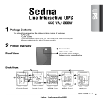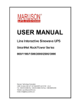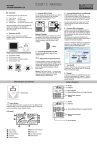
1
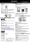
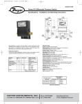
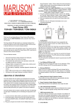
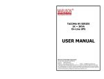
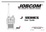
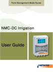
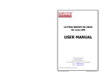
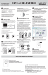
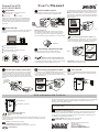
User's Manual
Power Pro UPS
400/600/800
Inspection
Connect UPS to power
The following items are inside the box:
User's Manual
UPS
Power cord
RJ11 Cable
Use the power cord that came with your UPS
to connect the UPS directly to the wall outlet.
conditioning, and surge protection. Battery power
is automatically provided in case of power failure.
Beware of the Power Switch it must be kept in the
"ON" position, otherwise, the UPS will be disabled
and your equipment will not be protected during a
power failure.
Remove Power Pro UPS from its package and
inspect it for damage that may have occurred
during,shipping. If any damage is discovered,
re-packn the unit and return it to the place of
purchase.
Monitor
Place the UPS
Provide 7.8 inch clearance on sides for adequate
airflow around the unit when placing beside a
monitor.
Battery Charging:
The UPS battery charges whenever the UPS is
connected to utility power and typically requires
less than eight hours to charge fully. Operating
runtime is reduced until the battery is fully charged.
Computer
Full Time Surge Protection Outlets (1)
20 cm
Connect a printer, fax machine, or scanner to the
"Full Time Surge Protection Outlet". This outlets
does not provide power during power failure.
Power Pro
8 hours
Avoid direct sunlight.
Avoid excessive heat.
Connecting equipment to UPS
Avoid excessive humidity or liquids.
Avoid excessive dust.
Printer
Connect the equipment to either, Battery
Power Supplied or Surge Protection outlets.
Battery Power Supplied Outlets (3)
Connect computer, monitor, and external drive to
the "Battery Power Supplied" outlets. These outlets
provide battery backup, EMI filtering, line
Modem/Phoneline Connection
Plug incoming internet line into the "In" socket at
the back of the UPS. Use one more Internet line
cable and plug one end of the Internet line cable
to the "Out" socket at the back of the UPS. Plug
the other end to the modem input socket as shown
below.
6
Connecting equipment to UPS
Scanner
CAUTION: Do NOT connect a printer to any
Battery Power Supplied outlet.
7
Turn On/Off
The Power Pro UPS 400/600/800 protects a single lineTo turn on the UPS unit, press the power switch
lightly. To turn off the UPS unit, press the power
(1 in/1out) phone, modem, or fax machine from
switch again.
surges when connected through the UPS as shown
in the chart below.
Incoming
Internet line
Modem
Power Pro
Phone
UPS Indicators and Controls
On/Off Button
Press and release the button to supply power to the Battery Power Supplied
Outlets. Press and release the button again to switch off power to the
Battery Power Supplied Outlets.
UPS Status Indicator
Power pro
Note: The Surge Protection Outlets are powered whenever the UPS
has utility power.
UPS Status Indicator(green)
Fault/ Low Battery/ Battery
Replacement Indicator
(red)
This indicator is lit whenever the UPS fault, and low battery occur, or the
battery is near the end of its useful life. The battery should be replaced
within two weeks.
Fault: continuously sounding
Low battery: sounding every second
Battery replacement: soundingevery 2 seconds
Powe r
On/Off Button
This indicator is lit when the UPS is supplying conditioned utility power to
the Battery Power Supplied Outlets. This indicator is flashing when the
utility power is outside acceptable limits and the battery is powering only
the Battery Power Supplied Outlets.
Battery Mode: sounding every 10 seconds
Overload: sounding every 0.5 seconds
Maruson Technology Corporation
P.O. BOX 1986,
WALNUT, CA 91788
Toll Free: 1-888-MARUSON
E-mail: Custsrv@MarusonUSA.com
Web Site: www.MarusonUSA.com
Power Pro UPS
400/600/800
User's Manual
Panel Information
When replacing batteries, replace with the same number
and type of sealed lead-acid battery.
This pluggable type A equipment with battery already installed
by the supplier is operator installable and may be operated
by laymen.
The mains socket outlet that supplies the UPS shall be installed
near the UPS and shall be easily accessible.
Modem/Phone Line
Surge Protection
Battery Power
Supplied Outlets
AC Input
During the installation of this equipment it should be assured
that the sum of the leakage currents of the UPS and the
connected loads does not exceed 3.5mA.
Circuit Breaker
Unplug the UPS prior to cleaning and do not use liquid or spray
detergent.
Full Time Surge
Protection Outlets
Trouble Shooting
Safety Caution
SAVE THESE INSTRUCTION-This manual contains
important instructions for models Power UPS 600
that should be followed during installation and
maintenance of the UPS and batteries.
This UPS utilizes voltage that may be hazardous. Do not
attempt to disassemble the unit. The unit contains no user
replaceable parts. Only factory service personnel may
perform repairs.
Internal battery voltage is 12Vdc.Sealed, lead-acid, 6 cells
battery.
Connection to any other type of receptacle other than a twopole, three-wire grounded receptacle may result in shock
hazard as well as violate local electrical codes.
In the event of an emergency, press the "OFF" button and
disconnect the power cord from the AC power supply to
properly disable the UPS.
Do not allow any liquids or any foreign object to enter the
UPS. Do not place beverages or any other liquidcontaining vessels on or near the unit.
This unit intended for installation in a controlled
environment (temperature controlled, indoor area free of
conductive contaminants). Avoid installing the UPS in
locations where there is standing or running water, or
excessive humidity.
Symptom
Possible Cause
No LED display 1. Bat ter y vo ltage too
on the front
low.
panel.
2. Bat ter y def ec t.
3. Pow er swi tch is not
pr es se d.
Alarm buzzer Ov erload of the UP S.
beeps
continuously
when AC
supply is
normal.
Remedy
1. Charge battery up to 8 hours.
2. Replace with the same type of
battery.
3. Press the power switch again.
Verify that the load mat ches the UPS
capability specified in the specs.
When power 1. Ov erload of the UPS . 1. Remove some noncritical load.
failure, backup 2. Ba ttery voltage is too
2. Charge battery 8 hours or more.
time is short.
low.
3. Ba ttery defect .
3. Replace with the same type of
battery.
Mains normal 1. Br eaker is trip.
1. Rese t the br ea ker.
but red and
2. Po we r cord is loose. 2. Reco nn ec t the po wer cor d
green LEDs
pr op er ly.
are flasing
If any abnormal situations occur that are not listed above, please call for
service immediately.
Specification
Do not plug the UPS input into its own output.
Do not attach a power strip or surge suppressor to the UPS.
Do not attach non-computer-related items, such as medical
equipment, life-support equipment, microwave ovens, or
vacuum cleaners to UPS.
To reduce the risk of overheating the UPS, do not cover the
UPS' cooling vents and avoid exposing the unit to direct
sunlight or installing the unit near heat emitting appliances
such as space heater or furnaces.
MODEL
CAPACITY
INPUT
OUTPUT
Do not dispose of batteries in a fire as they may explode.
A battery can present a risk of electrical shock and high
short circuit current. The following precautions should
be observed when working on batteries:
1) Remove watches, rings, or other metal objects from
the hands.
2) Use tools with insulated handles.
3) Wear rubber gloves and boots.
4) Do not lay tools or metal parts on top of batteries.
5) Disconnect charging source prior to connecting or
disconnecting batteries terminal.
Servicing of batteries should be performed or supervised
by personnel knowledgeable of batteries and the required
precautions. Keep unauthorized personnel away from
batteries.
VA/ W
6 Outlets
Do not open or mutilate the battery or batteries. Release
electrolyte is harmful to the skin and eyes. It may be
toxic.
Attention, hazardous through electric shock. Also with
disconnection of this unit from the mains, hazardous voltage
still may be accessible through supply from battery. The
battery supply should be therefore disconnected in the plus
and minus pole at the connectors of the battery when
maintenance or service work inside the UPS is necessary.
PRO-400USA PRO-600USAPRO-800USA
BATTERY
PROTECTION
PHYSICAL
400VA/240W
600VA/360W
800VA/480W
3 Batte ry with Surge Protectio n & 3 Surge Protectio n only
Voltage
110/120VAC or 220/230/240VAC
Voltage Ra nge
81-290VAC
Frequency
50/60Hz
Automatic
Voltage
+/ - 10%
Regulation (AVR)
Fr equ enc y
Regul at ion
50Hz or 60Hz +/- 1Hz
(Bat t. Mode )
Output
Si mul at ed Si ne wave
Waveform
Battery Type &
12V/4.5Ah x 1pcs 12V/7Ah x 1pc 12V/9Ah x 1pc
Number
Ba ckup Time (at
a PC load wi th
Up to 12 minu tes Up to 22 minu tes Up to 30 minutes
15" mon itor)
AC Surge
Protection
Phone/fax/
Modem
Surge Protection
Di mens ion
(in. ), DxW xH
Ne t Weight
Ful l time, 720 joul es
RJ-11
12.9X3.9X5.5
11. 02 3 lb.
13 .22 lb.
14 .33 lb.
Specification change without notice.
28-2BLA060027