1
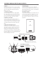
™
P1000 and P500 Subwoofers
User Manual
®
The lightning flash with arrowhead, within an equilateral triangle, is intended to
alert the user to the presence of uninsulated “dangerous voltage” within the
product’s enclosure that may be of sufficient magnitude to constitute risk of
electric shock to persons.
The exclamation point within an equilateral triangle is intended to alert the user
to the presence of important operating
and maintenance (servicing) instructions
in the literature accompanying this
product
WARNING
AVISIQUE
POUR EVITER TOUT RISQUE DE
CHOC ELECTRIQUE, NE PAS
DEMONTER LE COUVERCLE DU
HAUT PARLEUR. AUCUN ENTRETIEN DES PIECES INTERIEURES
N’EST REQUIS.TOUT SERVICE
D’ENTRETIEN NE DOIT ETRE
EFFECTUE QUE PAR DU PERSONNEL D’ENTRETIEN QUALIFIE.
DO NOT OPEN
TO PREVENT THE RISK OF ELECTRIC
SHOCK, DO NOT REMOVE
SUBWOOFER’S COVER. NO USERSERVICEABLE PARTS INSIDE.
REFER SERVICING TO QUALIFIED
SERVICE PERSONNEL.
READ AND HEED IMPORTANT SAFETY WARNING
ON BACK OF SUBWOOFER ENCLOSURE
CAUTION:
IMPORTANT NOTICE:
TO PREVENT ELECTRIC SHOCK, MATCH WIDE
BLADE OF PLUG TO WIDE SLOT, INSERT FULLY.
THE SERIAL NUMBER FOR THE SUBWOOFER IS
LOCATED ON THE SUBWOOFER’S CONTROL PANEL.
PLEASE WRITE THIS NUMBER DOWN AND KEEP IT
IN A SECURE AREA. THIS IS FOR YOUR SECURITY.
ATTENTION:
POUR EVITER LES CHOCS ELECTRIQUES, INTRODUIRE LA LAME LA PLUS LARGE DE LA FICHE
DANS LA BORNE CORRESPONDANTE DE LA PRISE
ET POUSSER JUSQU’AU FOND.
2
IMPORTANT SAFETY INSTRUCTIONS
READ INSTRUCTIONS – All safety and operating
instructions should be read before the subwoofer is
operated.
POWER-CORD PROTECTION – The AC power cords
should be routed so that they are not likely to be
walked on. No object should bring weight to bear on
to the AC power cords.
RETAIN INSTRUCTIONS – The safety and operating
instructions should be retained for future reference.
FOLLOW INSTRUCTIONS – All operating and use
instructions should be followed.
LIGHTNING – For added protection for the subwoofer
or control module during a lightning storm, or when it
is left unattended and unused for long periods of time,
unplug them from the wall outlet. This will prevent
damage to the subwoofer or control module due to
lightning and power-line surges.
CLEANING – Unplug the subwoofer or control module
from the wall outlet or other power source before cleaning. Use a damp cloth for cleaning.
OVERLOADING – Do not overload wall outlets, extension cords, or integral convenience receptacles as this
can result in a risk of fire or electric shock.
ATTACHMENTS – Do not use any adapters or attachments not recommended by Cambridge SoundWorks
as they may cause hazards.
OBJECT AND LIQUID ENTRY – Never use probes of
any kind to reach into the subwoofer or control module
as they may touch dangerous voltage points or short
parts that could result in a fire or electric shock. Never
spill liquid of any kind on the subwoofer, control module or control module power supply.
HEED WARNINGS – All warnings on the subwoofer
and in the operating instructions should be adhered to.
WATER AND MOISTURE – Do not use the subwoofer
or control module near water-for example, near a bath
tub, wash bowl, kitchen sink, or laundry tub; in a wet
basement; or near a swimming pool or other similar
areas.
SERVICING – Do not attempt to service the subwoofer
or control module yourself as opening or removing
covers may expose you to dangerous voltage or other
hazards. Refer all servicing to qualified service personnel.
ACCESSORIES – Do not place the subwoofer on an
unstable cart, stand, tripod, bracket, or table. The subwoofer may fall, causing serious injury to a child or
adult and serious damage to the product.
DAMAGE REQUIRING SERVICE – Unplug the subwoofer or control module from the wall outlet or other
power source and refer servicing to qualified service
personnel under the following conditions:
VENTILATION – Slots, openings and metal fins in the
cabinet are provided for ventilation, to ensure reliable
operation of the subwoofer and to prevent it from overheating. These areas must not be blocked or covered
such as by placing the product on a bed, sofa, very
deep pile rug, or other similar surface. The subwoofer
should not be placed in a built-in installation such as a
bookcase or rack.
a) When the power-cord or plug is damaged.
b) If liquid has been spilled, or objects have fallen into
the subwoofer or control module.
c) If the subwoofer or control module has been
exposed to rain or water.
HEAT – The subwoofer should be situated away from
heat sources such as radiators, heat registers, stoves,
and other products (including amplifiers) that produce
heat.
d) If the subwoofer or control module does not operate
normally by following the operating instructions; or
exhibits a distinct change in performance.
POWER SOURCES – The subwoofer or control module
should be operated only from the type of power source
indicated on the label. If you are not sure of the type of
power supply to your home, consult your dealer or
local power company.
e) If the subwoofer or control module has been
dropped or damaged in any way.
REPLACEMENT PARTS – When replacement parts
are required, be sure the service technician uses
replacement parts specified by Cambridge
SoundWorks or have the same characteristics as the
original part. Substandard substitutions may result in
fire, electric shock, or other hazards.
POLARIZATION – The subwoofer is equipped with a
polarized alternating-current line plug (a plug having
one blade wider than the other). This plug will fit into
the power outlet only one way. This is a safety feature.
If you are unable to insert the plug fully into the outlet,
try reversing the plug. If the plug should still fail to fit,
contact your electrician to replace your obsolete outlet.
Do not defeat the safety purpose of the polarized plug.
SAFETY CHECK - Upon completion of any service or
repairs to the subwoofer or control module, ask the
service technician to perform safety checks to determine that the subwoofer or control module is in proper
operating condition.
3
CONTENTS
1
1. Powered subwoofer enclosure
2. Control module
3. AC power cable
4. Module to sub interface cable
5. Remote control
6. Speaker wire connector plug
7. Control module power supply adapter
INSPECTING FOR DAMAGE
Examine each part carefully for shipping damage. If
there is any, do not install or use the system. Return
the subwoofer to the store or merchant where you
2
made the purchase or call Cambridge SoundWorks at
1-800 FOR-HIFI (1-800-367-4434) for assistance.
0
40
-6
100
20
0
70
0
50
er
equalizl
leve
er
equaliz cy
frequen
volume
phase
s
low-pas
SPECIFICATIONS
P1000:
7
Dimensions: 15 1/2"H x 15 1/4"W x 14"D
Weight: 45 pounds
P500:
Dimensions: 13 1/2"H x 13 3/4"W x 12"D
3
4
Weight: 35 pounds
VOLUME UP
5
VOLUME DOWN
VOLUME UP
VOLUME DOWN
SUBWOOFER VOLUME
SUBWOOFER VOLUME
6
4
OPERATING CONTROLS
Adjust it for maximum output in this narrow range (not
1. low-pass:
Even though a subwoofer only produces “bass
for “best sound”). The affect this control has can be
notes”, the upper end of its range should be tailored
subtle. It’s easiest to adjust when percussion is playing
to blend well with your main speakers. The sub-
a repetitive pattern.
woofer should not produce any bass your main
4. volume:
speakers can produce. The low-pass control sets
This control sets the overall output level of the sub-
this limit. The lowest setting (50 Hz) should be used
woofer. Adjust it with the remote control for the best
with large main speakers. Its middle settings should
overall blend with your main speakers, after you have
be used with small floorstanding speakers or large
set the other controls.
bookshelf speakers. Its highest setting should be
5. equalizer level and equalizer frequency:
used with small speakers (see table on page 14).
Your listening room’s shape and construction (and
2. On/Standby/Limit Indicator:
where you listen within it) have an unpredictable affect
This indicator glows amber when the subwoofer is
on deep bass. These two controls adjust deep bass.
in Standby. The subwoofer uses very little power in
equalizer frequency adjusts how deep into the bass
this mode. It turns on rapidly whenever the main
the subwoofer will respond. The 20 Hz setting indi-
system is used. This indicator glows green while the
cates the subwoofer is flat down to that frequency.
subwoofer is On and operating. This indicator blinks
equalizer level adjusts the output centered around the
red whenever the subwoofer reaches its full output
equalizer frequency setting.
(1000 watts for the P1000, 500 watts for the P500).
These controls let you discover the strong and deep
3. phase:
sonic events in your favorite program material, part of
The phase control compensates for placement dif-
the fun of having a great powered subwoofer.
ferences between the main speakers, the subwoofer
and your listening position. Adjusting this control
The lower you set the equalizer frequency and the higher
affects the relatively narrow range of notes where
you set the equalizer level, the more amplifier power you
the main speakers and the subwoofer “overlap”.
devote to producing the deepest bass.
This, in turn, can limit the maximum overall output of
your subwoofer. If you want maximum output, setting
the equalizer frequency at or above 30 Hz
can give it to you.
0
40
-6
100
20
0
70
0
50
r
equalize
cy
frequen
r
equalize
level
volume
phase
low-pass
40
100
70
0
130
50
150
0
180
low-pass
phase
1
3
2
0
11
volume
4
5
20
60
equalizer
frequency
5
-6
+6
equalizer
level
5
CONTROL MODULE INPUTS AND OUTPUTS
6. Sub In:
10. Main Outputs:
Connect the SUB OUT jack from a receiver, integrat-
Connect one of these two jacks to the subwoofer
ed amplifier, preamplifier, or surround decoder to this
enclosure using the supplied Interface Cable. Use the
jack. Use an audio signal cable with single RCA
other jack only when you to connect a second Newton
plugs on each end.
Series subwoofer enclosure.
7. Preamp Level Inputs:
The Remote Control
Normally, the Right (R) and Left (L) signal outputs
The Remote Control adjusts the motorized volume con-
from a preamp will connect to the to RIGHT IN and
trol. Because the output level of deep bass in a room
LEFT IN. The CENTER IN would only be used when
can vary substantially from one place to another, it’s
three equal-level signals need to be combined.
best to adjust the subwoofer’s output from your listen-
8. Speaker Level Inputs:
ing position.
Connect the Right and Left speaker outputs of a
stereo receiver/amplifier to the plug that inserts here.
Connect the Right, Center and Left speaker outputs
VOLUME UP
of a Dolby Surround receiver in WIDE mode to the
plug.
9. Right And Left High Pass Out:
VOLUME DOWN
Use these jacks if you have separate components
(preamplifier and power amplifier) and you want to
prevent the low frequency program material from
reaching your main speakers. Connect these signal
jacks to the Right (R) and Left (L) signal input jacks of
SUBWOOFER VOLUME
the power amplifier. Use a stereo audio signal cable
with two RCA plugs on each end.
Subwoofer Enclosure Input Panel
POWER
Powered
Subwoofer
120VAC
7.0A
INTERFACE JACKS
00000000
Connect the Interface Cable from the
Control Module to one of these two jacks.
9
6
9
Control Module Input Panel
CONTROL MODULE
NO USER SERVICEABLE PARTS INSIDE
REFER SERVICING TO QUALIFIED PERSONNEL
SUB IN
LEFT
HIGH PASS
OUT
RIGHT
HIGH PASS
OUT
Newton, Massachusetts USA
Made in China
+
–
+
–
+
INTERFACE JACKS
–
12V
AC INPUT
ON
AUTO
CENTER IN
LEFT IN
RIGHT IN
PREAMP LEVEL INPUTS
7
OFF
CENTER
LEFT
RIGHT
SPEAKER LEVEL INPUTS
8
6
1
10
2
PLACEMENT
The subwoofer enclosure should be placed on the
floor. Its location in the room affects its output. The output increases the closer the subwoofer is placed to the
intersection of walls and floors (see diagrams).
Some Advantages Of Corner Placement: Placing a
subwoofer in or near the corner of a room increases its
maximum output. Corner placement also provides the
most consistent output from deep bass to upper bass.
Since corner placement “forces” more of the bass
Maxium Bass Output
energy toward the center of the room, you can operate
the subwoofer at a lower overall gain setting than if it
was in the middle of a wall. This reduces the amount
of bass someone in a nearby room will hear.
Other locations: Any position in a room can be used,
but a position away from the intersection of two room
surfaces will both reduce the maxiumn output of the
subwoofer and make the output from deep bass to
upper bass less even.
For most places in a room, the orientation of the sub-
Moderate Bass Output
woofer is not critical. If you place the subwoofer directly in a corner, you may find that “diagonal” placement
(the grille panels forming a 45 degree angle with both
side walls) reduces wall-shaking.
We realize many “real world” factors affect where you
choose to place a subwoofer and corner placment
may not be practical. The highly flexible controls on
the Control Module allow you to effectively compensate for uneven output due to placement.
Least Bass Output
Ventilation: Because the subwoofer enclosure panel
requires adequate ventilation, do not
place it inside a wall unit or any piece of
furniture. Also, don’t place it near heat
sources or against furniture, draperies or other material that will block the free flow of air around the from
underneath the subwoofer.
7
INSTALLING CARPET SPIKES
Improving Stability With Carpet Spikes
Back
The powered subwoofer has four soft feet for level,
stable orientation on any flat surface and tightly woven
carpets. Installing and adjusting the four carpet spikes
can level the speaker and improve its stability on thick
carpeting. The spikes penetrate a carpet and carpet
pad and transfer the weight of the speaker directly to
the floor surface.
Note: These carpet spikes will leave four small but
distinct puncture holes in wooden floors and could
damage other surfaces, especially if the subwoofer is
Front
dragged after they are installed. Do not use these
spikes if you are concerned about the appearance of
the floor beneath the carpet.
Carpet spike installation consists of installing, adjusting, and locking the spikes. Determine the final position of the subwoofer before installing the carpet
spikes, since repositioning a subwoofer is very difficult
once the spikes are installed.
1) Screw one locknut about half-way down the shank
of each carpet spike.
2) Prepare a soft surface on the floor in front of the
subwoofer’s final position. Carefully upend the subwoofer so that its front panel (the one with the logo)
rests on the soft surface.
3) Screw each carpet spike into one of the four threaded fittings. Leave a small gap between the locknut
and the fitting.
4) Replace the subwoofer at its proper listening position. Adjust the spikes by lifting the subwoofer on
the appropriate side and rotating the spikes until
the speaker is level and stable.
5) Hand tighten each locknut (or use a wrench)
against the base to secure the carpet spike, taking
care not to rotate the spike.
8
CONNECTIONS
RECEIVER
After you have positioned the subwoofer enclosure,
DIGITAL INPUTS
to connect the Control Module to your audio
SPEAKER OUTPUTS
COAX
MAIN RIGHT
OPTICAL
components.
MAIN LEFT
CENTER
SUB OUT
About your audio components: You can connect the
REAR RIGHT
Control Module to a receiver, an integrated amplifier, a
SIGNAL CABLE
WITH RCA PLUGS
REAR RIGHT
preamplifier/power amplifier combination or other
This jack is usually labeled "SUB OUT," but it may
say "SUBWOOFER" or "LFE OUTPUT". Check
the receiver owner's manual to identify it.
audio component with line level or speaker level outputs. For brevity, this guide will usually refer only to a
CONTROL MODULE
NO USER SERVICEABLE PARTS INSIDE
REFER SERVICING TO QUALIFIED PERSONNEL
SUB IN
“receiver,” but the instructions will also apply to any
LEFT
HIGH PASS
OUT
RIGHT
HIGH PASS
OUT
Newton, Massachusetts USA
Made in China
+
–
+
–
+
INTERFACE JACKS
–
12V
AC INPUT
ON
audio component.
AUTO
OFF
CENTER IN
LEFT IN
RIGHT IN
PREAMP LEVEL INPUTS
You can connect the Control Module to a receiver’s line
CENTER
LEFT
RIGHT
SPEAKER LEVEL INPUTS
1
2
Dolby Digital and Dolby Surround receiver
Line level connector
level output (one or two RCA jacks) or its speaker level
outputs, but not both. Always disconnect the AC
power to the Control Module and the subwoofer enclosure before making or changing any connections.
Line Level Connections
For most line level connections, you need a signal
INPUTS
R
POWER
AMPLIFIER
L
cable with an RCA plug at both ends. Connect the
IN
Control Module in the following ways:
Dolby Digital receiver: Connect a mono signal cable
from the RCA jack output labeled SUB OUT (or possibly labeled LFE or just SUB) on the receiver to the
SUB IN input on the Control Module.
CONTROL MODULE
NO USER SERVICEABLE PARTS INSIDE
REFER SERVICING TO QUALIFIED PERSONNEL
SUB IN
LEFT
HIGH PASS
OUT
RIGHT
HIGH PASS
OUT
Dolby Surround receiver (with or without Pro Logic):
Connect a signal cable from the SUB OUT RCA jack
(also labeled LINE OUT, AUDIO OUT, or just SUB) to
the SUB IN input on the Control Module.
Newton, Massachusetts USA
Made in China
+
–
+
–
+
00000000
INTERFACE JACKS
–
12V
AC INPUT
ON
AUTO
OFF
CENTER IN
LEFT IN
RIGHT IN
PREAMP LEVEL INPUTS
Preamplifier/power amplifier: Connect a stereo signal cable with RCA plugs at each end from the LEFT
and RIGHT preamp outputs to the RIGHT IN and
LEFT IN inputs on the Control Module. Connect
another stereo signal cable from the RIGHT HIGHPASS OUT and LEFT HIGH-PASS OUT outputs of
the Control Module to the LEFT and RIGHT inputs on
your stereo power amplifier (or the FRONT LEFT
and FRONT RIGHT inputs of a multi-channel power
amplifier.)
CENTER
LEFT
RIGHT
SPEAKER LEVEL INPUTS
1
2
INPUTS
R
L
CD
IN
IN
IN
OUTPUTS
R
AUX
TAPE
OUT
TAPE
L
IN
PREAMP
IN
OUT
Preamplifier/Power amplifier level connectors
Once your line-level connection is made between the
receiver and Control Module, skip to “Connect the
Subwoofer Enclosure,” page 11.
9
Speaker Level Connection
TO FRONT LEFT &
RIGHT SPEAKERS
If your receiver does not have a line-level audio signal
output or if you wish to bypass this output, you need to
connect the speaker level inputs of the Control Module
DIGITAL INPUTS
to your receiver’s speaker outputs.
SPEAKER OUTPUTS
COAX
MAIN RIGHT
OPTICAL
We provide a Speaker Wire Connector with two short
Red Band
MAIN LEFT
lengths of speaker wire already connected to it. (If
White Band
CENTER
wires are not long enough to reach from the Control
SUBWOOFER
Module to your power amplifier, you need to attach
REAR RIGHT
OUT
longer speaker wires. How to do this is described in
REAR RIGHT
“Attaching longer speaker wires” at the bottom of
this page.)
Connect plug to speaker output
TO SUB'S
SPEAKER LEVEL
INPUTS
The speaker wire marked with a red band is Right
postive. The unmarked wire next to it is Right negative.
The Left Positive speaker wire is marked with a white
5/8"
band. The unmarked speaker wire next to it is
Left negative.
Ridge on
One Side
receiver end
Connect the speaker wires to your receiver’s Left and
Cambridge SoundWorks Camb rid
ge So
und
Works Cambride
Printing on
One Side
Right speaker outputs (Front Left and Front Right
speaker outputs of a multi-channel receiver). You will
have to “parallel connect” theses wires with the main
Different
Color
Conductors
connector end
speaker wires (see diagram). Positive speaker output
3/8"
terminals will usually be colored red and have a “+”
Prepare Wire
Identify Wire Marking
symbol. Negative speaker output terminals will usually
be colored black and have a “–” symbol.
Finally, insert the Speaker Wire Connector plug into the
LEFT
Connect plug to
Control Module
Note
Positive (+)
Negative (–)
Sequence
Attaching longer speaker wires: First, prepare two
suitable lengths of speaker wire. You can use lightweight (18-22 gauge) speaker wire because this wire
will not carry any significant electric current. Also, wire
RIGHT
(CENTER)
larger than 18 gauge will be somewhat harder to
connect in tandem with another speaker wire.
Strip off 5/8” of insulation from one end of each
MODULE
CONTROL
INSIDE
E PARTS
SERVICEABL FIED PERSONNEL
NO USER
QUALI
CING TO
REFER SERVI
speaker wire. Strip of 3/8” of insulation from the other
SUB IN
end. This end connects to the Speaker Wire
RIGHT
USA
achusetts
Newton, Massin China
Made
LEFT
HIGH PASS
OUT
–
+
HIGH PASS
OUT
+
–
+
CENTER
S
RIGHT
LEVEL INPUT
SPEAKER
Wire Connector to Module
10
ON
AUTO
OFF
1
LEFT IN
IN
CENTER
S
RIGHT IN
LEVEL INPUT
PREAMP
Connector Plug.
12V
AC INPUT
JACKS
INTERFACE
–
LEFT
2
jack in the Control Module.
Tighten each set screw to hold the wires in place.
To insure you connect the wires properly (positive to
Connect to the Subwoofer Enclosure: Once the
positive, negative to negative), note which of each
input connections are made to the Control Module,
speaker wire’s two conductors is “marked”. This mark-
connect the Interface Cable from the Control Module
ing may be a ridge in the insulation, different colored
to the Subwoofer Enclosure.
conductors or printing on only one side. Use the
The interface Cable has plugs that look and connect
marked side of the speaker wire to connect the posi-
like telephone connector plugs. The plugs are the
tive speaker terminals. Use the other wire for the nega-
same at both ends.
tive terminals.
Making sure both the Control Module and
Using a small flat bladed screwdriver, loosen the four
subwoofer enclosure are disconnected
set screws inside the Speaker Wire Connector plug.
from any AC power source.
Pull out the short speaker wires.
Note: The second Interface Cable jack on the subFollowing the markings on the Speaker Wire Connector
woofer enclosure allows you to connect a Newton
diagram (for Right positive, Right negative and so on),
Series second subwoofer enclosure with a sub to sub
insert the correct wires into the plug’s openings.
MODULE
CONTROL
INSIDE
E PARTS
SERVICEABL FIED PERSONNEL
NO USER
QUALI
CING TO
REFER SERVI
SUB IN
USA
achusetts
Newton, Massin China
Made
LEFT
HIGH PASS
OUT
RIGHT
+
HIGH PASS
OUT
LEFT
IN
CENTER
S
RIGHT IN
LEVEL INPUT
PREAMP
IN
–
+
–
+
CENTER
S
RIGHT
LEVEL INPUT
SPEAKER
12V
AC INPUT
JACKS
INTERFACE
–
ON
Powered
Subwoofer
AUTO
POWER
OFF
LEFT
1
120VAC
7.0A
2
00000000
INTERFA
CE JACKS
11
FINAL SETUP
interface cable.
Power Connections
First, insert the AC plug of the Control Module’s power
Powered
Subwoofer
supply adapter into an AC outlet. Then insert the
POWER
120VAC
7.0A
00000000
INTERFAC
E JACKS
adapter’s output plug into the Control Module’s
12V AC input jack. Turn the Control Module’s power
switch to AUTO.
Insert the subwoofer enclosure’s power cable into the
receptacle on the subwoofer enclosure’s input panel.
Then insert the AC plug into an AC outlet. Turn the
subwoofer enclosure’s power switch ON.
SUB IN
RIGHT
HIGH PASS
OUT
Remote Control
LEFT
HIGH PASS
OUT
NO USER
+
CONTROL
MODULE
SERVICEABLE
Newton, Massac
REFER SERVICIN
PARTS INSIDE
husetts
G TO QUALIFIE
Made in China USA
D PERSON
NEL
–
+
–
+
–
INTERFACE
JACKS
RIGHT IN
CENTER IN
LEFT IN
PREAMP LEVEL
INPUTS
The remote control adjusts the VOLUME setting, an
AUTO
1
adjustment best made from your listening position.
The battery inside the remote should last for a year or
two. When you need to replace it, use a small pointed
object (paper clip, pen, toothpick) to release the battery holder (see diagram). The battery type is CR2032
(3V) and is available wherever wrist watch and hearing
aid batteries are sold.
Test Your Connections
VOLUME UP
Once all connections have been made, test your
sound system to verify the subwoofer produces bass
VOLUME DOWN
output. Advance the Bass Level control to the
10 o’clock position. Turn on your receiver and play a
CD or movie you know to have significant bass. Listen
for subwoofer output as you increase your receiver’s
SUBWOOFER VOLUME
volume control up to a moderate volume level. If you
don’t hear any output from the subwoofer, slowly
advance the subwoofer’s Bass Level (preferably via
the remote control). If you don’t get any output,
12
12V
AC INPUT
ON
RIGHT
CENTER
SPEAKER
LEVEL INPUTS LEFT
2
OFF
0
40
recheck your connections.
Adjusting For Best Performance
We recommend you adjust the Control Module according to the following sequence:
20
1. Set the equalizer controls.
-6
60
+6
equalizer
level
equalizer
frequency
2. Set the low pass control.
3. Set the volume control by ear.
1. Set The Controls
4. Set the phase control by ear.
5. Reset the volume control (if necessary).
6. Adjust the equalizer frequency and equalizer level
controls to your preference.
0
Adjustment:
40
-6
100
1. Start with the equalizer level set to 0 (straight up)
20
0
70
0
and the equalizer frequency control set to approxi-
50
volume
phase
low-pass
mately 30 Hz (see diagram at the top of the page).
2. Adjust the low pass control according to the Low
Pass Control Settings Table on the opposite page.
VOLUME UP
3. Set the subwoofer’s volume with the supplied
remote control. Use some of your favorite program
VOLUME DOWN
material (video or audio). Adjust the output level
until you are happy with the overall bass balance.
4. Adjust the phase control. This control’s action will
SUBWOOFER VOLUME
be subtle. Make this adjustment from your listening
3. Adjust Volume
position. If the control module is not within easy
reach, have someone else adjust this control while
you listen.
phase control adjustment: Play some program material with constant, regular bass (like a kick drum
beat). Rotate the phase control back and forth
across its full range and listen for an increase in output. The output difference you hear could be anything from negligible to significant. However large
0
the difference, leave this control set where it has the
180
phase
maximum effect.
4. Adjust Phase
If you do not hear any difference in the bass output,
skip Step 5.
13
er
equaliz cy
frequen
er
equalizl
leve
2. LOW-PASS CONTROL SETTINGS
The low-pass control on the front panel of the Control Module is continuously variable from
50 Hz to 150 Hz. The following recommendations describe setting the control at the five indicated
positions on the dial (50, 70, 100, 130, and 150 Hz), but intermediate settings are also functional.
Dolby Digital sound systems
100
A Dolby Digital decoder
provides its own “bass
management” processing
when you activate the
decoder’s “SUB OUT” jack.
Set the Newton Series powered subwoofer’s low-pass
control to 150 Hz in this
case.
®
100
70
130
50
150
low-pass
70
130
50
100
70
130
50
150
130 Hz
100
70
130
50
low-pass
100 Hz
100
130
50
150
70 Hz
The following recommendations apply when both
your main left and right speakers and your subwoofer are driven by a full range signal. This is
the case in a stereo component system or a
Dolby Surround with Pro Logic system.
100
70
130
50
150
low-pass
50 Hz
14
Use this setting for large size bookshelf speakers and small floor standing speakers. Use this setting with
these Cambridge SoundWorks main
speakers:
Model 6
Tower III
Newton Series M60
Newton Series M80
Newton Series MC500
low-pass
Dolby Surround (Pro Logic) and
Stereo sound systems
Use this setting for medium size
bookshelf speakers. Use this setting
with these Cambridge SoundWorks
main speakers:
Model 17
Ambiance 62
Ambiance 82
Newton Series M50
Newton Series MC300
150
70
Use this setting for larger satellite
main speakers and the smallest bookshelf speakers. Use this setting with
these Cambridge SoundWorks main
speakers:
Ambiance 52
MovieWorks satellites
Ensemble satellites
Ensemble II satellites
Newton Series MC200
low-pass
Stereo sound systems using the
Control Module’s high-pass outputs.
The Control Module’s high-pass outputs block all
low frequencies below 100
Hz. Set the low-pass control
100
on the front panel no lower
than 100 Hz when using
70
130
these outputs. If your main
speakers are medium-sized
50
150
bookshelf speakers or
low-pass
smaller, set the low-pass
control to 130 Hz or 150 Hz,
100 Hz
as described in the Dolby
Surround (Pro Logic) and Stereo sound section
that follows.
Ensemble III satellites
Ensemble IV satellites
150 Hz
150 Hz
Note: Be sure to set the LARGE SPEAKER/
SMALL SPEAKER option for the Front, Center
and Rear channels of the Dolby Digital decoder.
Unless your main speakers are quite large (floorstanding types with a ten inch woofer or larger),
we recommend choosing the SMALL SPEAKER
option. This insures a smooth transistion
between your main speakers and the Newton
Series subwoofer, and that the subwoofer handles all the deep bass output.
150
low-pass
Use this setting for small “satellite”type main speakers (“minispeakers”)
or any speaker with a single four-inch
low frequency driver or smaller. Use
this setting with these Cambridge
SoundWorks main speakers:
Use this setting for large floor-standing speakers. Use the setting with
these Cambridge SoundWorks main
speakers:
Tower II
Tower
Newton Series T300
Newton Series T500
0
40
5. If you find the increase in output contributed by the
phase control is more than you care for, reduce the
6. Set the Controls
volume control setting to bring the subwoofer output
-6
back in balance.
+6
equalizer
level
20
60
equalizer
frequency
Congratulations! You have now adjusted the subwoofer to blend well with your main speakers.
d) You may wish to repeat this adjustment procedure
with some different musical or video program pas-
6. The equalizer frequency and equalizer level
sages. Remember, there is no “perfect” setting for
controls:
these controls. Once you have found a setting is
Your listening room’s shape and construction have an
good for a few recordings, you can reliably consider
unpredictable but significant effect on how strong the
the adjustment complete.
deep bass output is at your listening position. These
controls adjust the strength of the deep bass without
Normal Use:
affecting the subwoofer’s blend with the main speak-
Afterwards, if you find you want more or less bass out-
ers. Follow this last procedure to adjust them.
put from your system, either adjust any available tone
a) Adjust the equalizer level setting up to about
controls on your receiver or adjust the volume control
3 o’clock (see diagram in next column). From your
on the Control Module.
listening position, play the passage you used previ-
We hope you enjoy the new sonic dimensions your
ously to adjust the subwoofer volume. It should be
Newton Series powered subwoofer reveals to you!
easy to hear the effect of the control on deep bass
content. Repeat the passage at different equalizer
Fuse Replacement
level settings. Make sure you assess the settings
The fuse holder is located on the base of the sub-
from your normal listening position. Leave the con-
woofer. Both subwoofer models use a metric 5X20mm
trol at your preferred setting.
size fuse, 7A.
b) Play the same passage again and listen to higher
To replace the fuse:
1) Unplug the AC cord from the AC power source, then
remove the AC power cord from the speaker.
2) Remove the fuse cap with a small, flat blade screwdriver (see first and second diagram).
3) Replace the fuse inside the fuse cap with another
metric 5X20mm size fuse, 7 A (see third diagram).
4) Replace the fuse and cap in the subwoofer.
5) Restore the sub to an upright position.
6) Connect the AC power cord first to the subwoofer
and then to the power source.
and lower settings of the equalizer frequency control from your preferred listening posititon.
For recordings with deep bass content, setting the
equalizer frequency control below 30 Hz will produce
highly accurate and room-shaking results as it reveals
near-infrasonic signals. There are only two main reasons to set this control above 20 Hz – the very deep
bass bothers people in adjoining rooms or the overall
output level isn't as strong as you would like.
If you have a large room, or desire very high
sound pressure levels, setting the equalizer
frequency control at 30 Hz or higher will still
7A 250V
overall output.
FU
FU
SE
RISK OF FIRE
REPLACE FUSE
AS MARKED
SE
provide good deep bass, but will allow greater
T
Fuse Replacement
15
P81-1630 Rev A