1
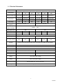
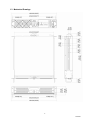
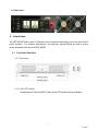
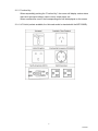
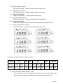
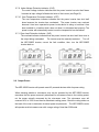
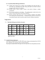
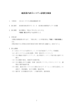
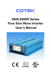
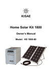
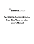
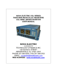
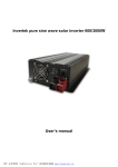
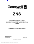
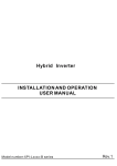
AEP-3000R Series
Rackmount Pure Sine Wave Inverter
User Manual
200 Butterfield Drive, Ashland, MA 01721, Tel: (508)881-7330, Fax: (508)231-0861
Website: http://www.schaeferpower.com, Email: sales@schaeferpower.com
January 2007
Table of Contents
1. Features
1-1 Applications
1-2 Electrical performance
1-3 Mechanical drawings
1-4 Rear panel
2
3
4
5
2. Introduction
2-1 Front panel operations
2-2 Rear panel operations
2-3 Installation
2-4 Quick hook up and testing
2-5 AC safety grounding
2-6 Making DC wiring connections
2-7 Inverter operation
2-8 Output power
2-9 Cooling fan operation
5-6
7
8
8-9
9-10
10-11
11-13
13-14
14
3. Maintenance ……………………………………………………………….………………. 14
4. Troubleshooting Guide …..……………………………………………………………… 15
5. Warranty …………………………………………………………………………..……….. 16
6. Important Safety Instructions
6-1 General safety precautions
6-2 Precautions when working with batteries
16
17
7. Appendix A
7-1 Dip switch settings
7-2 Variable output adjustment
17
17
1
1/24/2007
1. Features:
Pure sine wave output (THD < 3%)
Auto bypass function
Output frequency: 50 / 60Hz switch selectable
RS–232C interface / remote control port / wire connection to PC
Wired remote control (optional)
Thermostatically controlled cooling fan
Advanced microprocessor design
Protection :
Input low voltage
Overload
Short circuit
Low battery alarm
Input over voltage
Over temperature
1-1
Applications
1-1-1 Power tools – circular saws, drills, grinders, sanders, buffers, landscaping tools, air
compressors.
1-1-2 Office equipment – computers, printers, monitors, facsimile machines, scanner.
1-1-3 Central office – data centers
1-1-4 Factory automation – backup control systems
1-1-5 Household items – vacuum cleaners, fans, fluorescent and incandescent lights, shavers,
sewing machines,
1-1-6 Kitchen appliances – microwave ovens, refrigerators and freezers, coffee makers,
blenders, ice markers, toasters.
1-1-7 Industrial equipment – metal halide lamp, high pressure sodium lamp.
1-1-8 Home entertainment/electronics - television, VCRs, video games, stereos, musical
instruments, satellite equipment.
2
1/24/2007
1-2 Electrical Performance
Specification
AEP-3000R Series
Model Number
AEP-3000R- AEP-3000R- AEP-3000R- AEP3000R- AEP-3000R- AEP-3000R121
241
481
122
242
482
Continuous Output Power 2250W (3KVA) 2400W (3KVA) 2550W (3KVA) 2100W (3KVA) 2400W (3KVA) 2550W (3KVA)
Surge Rating
Input Voltage
Output Voltage
Regulation
2475W/1Min
2640W/1Min
2805W/1Min
2475W/1Min
2640W/1Min
2805W/1Min
2700W/20Sec
2880W/20Sec
3060W/20Sec
2700W/20Sec
2880W/20Sec
3060W/20Sec
12V
24V
48V
12V
24V
48V
100 /110/115 /120V RMS ±3%
200 / 220 / 230 / 240V RMS ±3%
Frequency
50/60Hz ± 0.05%
(Switch Selectable)
Peak Output Current
30A
15A
Efficiency (full load)
84%
86%
87%
85%
88%
90%
No Load Current Draw
1.54A
0.82A
0.37A
2.3A
1.42A
0.6A
Output Waveform
R Load Sine Wave <3% THD
Output Voltage Range
Input Voltage Regulation
VAC 100~120V (Adjustable)
VAC 200~240V (Adjustable)
10-16
20-32
42-62
10-16
20-32
42-62
VDC
VDC
VDC
VDC
VDC
VDC
Protection
Overload, Short Circuit, Reverse Polarity (Fuse), Over/Under Input Voltage, Over Temperature.
Digital Display
OVP : UVP : OTP : OLP : VAC : AMP : WATT : VDC : TEMP : Hz
Interface Control Port
RS-232C With Baud Rate 2400,4800, 9600, 19200 (Switch Selectable)
Remote Control Unit
Optional
AC Input
AC110V (90~130V)
AC220V (180~260V)
AC Frequency
50Hz ~ 60 Hz
50Hz ~ 60 Hz
Bypass
4~6ms
4~6ms
Operating Temperature
Range
-30 to +60°C (-22 to +140°F)
Storage Temperature
Range
-30° to +70°C (-22 to +158°F)
Dimensions (L x W x H)
435 x 424 x 88.4 mm (17.12” x 19” x 3.48”)
Weight
9.8 kgs (21.60 lbs.)
3
1/24/2007
1-3 Mechanical Drawings
4
1/24/2007
1-4 Rear Panel
2. Introduction:
The AEP-3000R Series is part of Schaefer’s line of advanced technology, pure sine wave DC/AC
power inverters. For optimum performance, the instruction manual should be read to ensure
proper installation and use of the AEP-3000R.
2-1
Front Panel Operation:
2-1-1 Front view:
2-1-2 ON / OFF Switch:
Please keep the Power ON/OFF switch in the OFF position during installation.
5
1/24/2007
2-1-3 Function Key
When sequentially pushing the “Function Key”, the screen will display various status
items such as output voltage, output current, output power, etc.
When a malfunction occurs, the corresponding error will be displayed on the screen.
2-1-4 AC Outlet (sockets available; the Universal socket is standard with the AEP-3000R):
6
1/24/2007
2-2 Rear Panel Operation:
2-2-1 Ventilation openings:
Do not obstruct; allow at least 3 inches for airflow.
2-2-2 Battery terminals:
Connect to a 12VDC/24VDC/48VDC battery or other 12VDC/24VDC/48VDC power
source.
Red [+] is positive; black [-] is negative. Reverse polarity connection will blow the
internal fuse and may damage inverter permanently.
WARNING!
Do not connect the 12VDC model to a 24VDC battery.
The unit will be destroyed immediately!
2-2-3 RS-232C:
Connect to remote control unit (optional accessory) or connect to computer for
remote control working status.
2-2-4 Connect chassis ground terminal to earth or to vehicle chassis using # 8 AWG wire.
WARNING!
Operation of the inverter without a proper ground
connection may result in an electrical safety hazard
WARNING!
Shock Hazard! Before proceeding, carefully check the
AEP-3000R inverter is NOT connected to any batteries and
is disconnected from any electrical source. Do not
connect the output terminals of the AEP-3000R to an
incoming source at this time.
7
1/24/2007
2-3 Installation:
Where to install:
The power inverter should be installed in a location that meets the following requirements:
2-3-1 Dry: Do not allow water to drip or splash on the inverter.
2-3-2 Cool: Ambient air temperature should be between 0C and 40C.
2-3-3 Safe: Do not install in a battery compartment or other areas where flammable fumes
may exist, such as fuel storage areas or engine compartments.
2-3-4 Ventilated: Allow at least three inches of clearance around the inverter for air flow,
ensuring that the ventilation openings on the rear and bottom of the unit are not
obstructed.
2-3-5 Dust Free: Do not install the AEP-3000R Inverter in a dusty environment where dust,
wood particles or other filings/shavings are present that may be pulled into the unit
when the cooling fan is operating.
2-3-6 Close to Batteries: Avoid excessive cable lengths but do not install the AEP-3000R
Inverter in the same compartment as batteries.
Use the recommended wire lengths and sizes (see section 2-6).
Avoid mounting the AEP-3000R Inverter where it may be exposed to the gases
produced by the battery. Prolonged exposure to these corrosive gases will damage
the AEP-3000R Inverter.
2-4 Quick Hook Up and Testing:
2-4-1 Unpack and inspect the power inverter, verifying that the power switch in the OFF
position.
2-4-2 Connect the cables to the power input terminals on the rear panel of the power
inverter. The red terminal is positive (+) and black terminal is negative (-). Insert
the cables into the terminals and tighten the nut to securely clamp the wires.
WARNING!
You may observe a spark when you make this connection as
current may flow to charge the capacitors in the inverter.
Do not make this connection in the presence of flammable
fumes. Explosion or fire may result!
2-4-3 Before proceeding, confirm that your cable is connected from the negative terminal of
inverter to the negative output of your power source.
8
1/24/2007
2-4-4 Connect the cable from the positive terminal of the inverter to the positive terminal of
the power source. Make a secure connection.
CAUTION!
Reverse polarity connection will blow a fuse in the inverter and
may cause damage. Damage caused by reverse polarity
connection is not covered by our warranty
WARNING!
Make sure that all DC connections are tight (torque to
9-10 foot pounds). Loose connections will overheat and
could result in a potential hazard
2-4-5 Set the power switch to the ON position; you will hear a beeping sound, while the
display shows the word “ASIAN” twice. After that, you will hear a continuous
tone from the internal alarm. Finally, the AC voltage shows on the display,
signaling that the inverter has completed the start up operation.
2-4-6 Set the power switch to the OFF position; the device will shut down completely.
2-4-7 Please use a power meter to accurately measure the true output R.M.S. voltage of
inverter.
2-5 AC Safety Grounding:
During the AC wiring installation, AC input and output ground wires are connected to the
inverter. The AC input ground wire must connect to the incoming ground from your AC utility
source. The AC output ground wire should go to the grounding point for your loads (for
example, a distribution panel of bus chassis).
2-5-1 Neutral Grounding (GFCI’s):
2-5-1-1 120VAC Models:
The neutral conductor of the AC output circuit of the AEP-3000R Inverter is
automatically connected to the safety ground during inverter operation. This
conforms to national electrical code requirements stating that separately derived
AC sources (such as inverters and generators) have their neutral conductors tied
to ground in the same way that the neutral conductor from the utility is tied to
9
1/24/2007
ground at the GFCI breaker panel. For models configured with a transfer relay,
while AC utility power is present and the inverter is in bypass mode, this
connection (neutral of the inverter’s AC output to input safety ground) is not
present so that the utility neutral is only connected to ground at your breaker
panel, as required.
2-5-1-2
230VAC Models:
There is no connection made inside the AEP-3000R Inverter from either the line
or neutral conductor to the safety ground.
WARNING!
Do not operate the power inverter without connecting it to
ground. Electrical shock hazard may result.
2-6.
Making DC Wiring Connections:
Follow this procedure to connect the battery cables to the DC input terminals on the
AEP-3000R Inverter. Your cables should be as short as possible (ideally, less than 10
feet / 3 meters) and large enough to handle the required current in accordance with the
electrical codes or regulations applicable to your installation.
Cables that are not an adequate gauge (too narrow) or are too long will cause
decreased inverter performance such as poor surge capability and frequent low input
voltage warnings and shutdowns.
These low input voltage warnings are due to DC voltage drop across the cables from the
inverter to the batteries. The longer and narrower these cables, the greater the voltage
drop.
WARNING!
The installation of a fuse must be on positive cable. Failure to
place a fuse on “+ “cables running between the inverter and
battery may cause damage to the inverter and will void
warranty.
Increasing your DC cable size will help improve the situation. We recommend the
following cables for optimum inverter performance. Use only high quality copper wiring
and keep cable length short (from 3-6 feet).
10
1/24/2007
Model No
Wire AWG
Inline Fuse
AEP-3000R-121
#4/0
400A
AEP-3000R-122
#4/0
400A
AEP-3000R-241
#2/0
200A
AEP-3000R-242
#2/0
200A
AEP-3000R-481
#1/0
100A
AEP-3000R-482
#1/0
100A
2-7 Inverter Operation:
To operate the power inverter, turn it on using the ON/OFF switch on the front panel. The
power inverter is now ready to deliver AC power to your loads.
If you are operating several loads from the power inverter, turn them on separately after the
inverter has been turned on. This will ensure that the power inverter does not have to
deliver the starting currents for all the loads at once.
2-7-1 Controls and indicators:
The ON / OFF switch turns the control circuit in the power inverter on and off.
The AEP-3000R Inverter operates from an input voltage ranging from:
10.5 to 15.0 VDC for 12VDC models
21.0 to 30.0 VDC for 24VDC models
42.0 to 60.0 VDC for 48VDC models
The AEP-3000R Inverter will indicate high and low DC voltage conditions as follows:
Model
Dc Input over Dc Input over
Dc Input
Dc Input under
voltage
under
voltage alarm
voltage
shut-down
voltage alarm shut-down
AEP-3000R-121
AEP-3000R-122
16.0VDC
15.5VDC
10.5VDC
10.0VDC
32.0VDC
31.0VDC
21.0VDC
20.0VDC
62.0VDC
61.0VDC
43.0VDC
42.0VDC
AEP-3000R-241
AEP-3000R-242
AEP-3000R-481
AEP-3000R-482
11
1/24/2007
2-7-2 Output Voltage Indicator:
VAC LED illuminated. Display indicates output voltage value.
2-7-3 Output Current Indicator:
AMP LED illuminated. Display indicates output current value.
2-7-4 Output Watts Indicator:
Watts LED illuminated. Display indicates Watts value.
2-7-5 Input DC Voltage Indicator:
VDC LED illuminated. Display indicates input DC voltage value
2-7-6 Temperature Indicator:
TEMP LED illuminated. Display indicates internal operating temperature value.
2-7-7 Output Frequency DC Indicator:
Hz LED illuminated. Display indicates output frequency value
The accuracy of the six display functions is below:
Functions
Ranges
Accuracy
VAC
AMP WATT
VDC
100-120 200-240
10-16
0-30A 0-3KW
VAC
VAC
VDC
± 1%
± 1%
± 1%
± 3%
± 2%
TEMP
Frequency
20-32 42-62
0-120
VDC VDC
50Hz
60Hz
± 2%
±0.01
±0.01
± 2%
± 1%
2-7-8 Over Voltage Protection Indicator: (OVP)
The over voltage indicator indicates that the power inverter has shut itself down
because its input voltage exceeded the limits of the inverter (see Page 12).
12
1/24/2007
2-7-9 Under Voltage Protection Indicator: (UVP)
The under voltage indicator indicates that the power inverter has shut itself down
because its input voltage fell below the limits of the inverter (see Page12).
2-7-10 Over Temperature Protection Indicator: (OTP)
The over temperature indicator indicates that the power inverter has shut itself
down because the inverter has overheated. The power inverter may overheat
because it has been operated at power levels above its rating or because it has
been installed in a location which does not allow it to dissipate heat properly. The
power inverter will automatically restart, once the temperature has decreased.
2-7-11 Over Load Protection Indicator: (OLP)
The overload indicator indicates that the power inverter has shut itself down due to
the output being overloaded. The inverter must be manually restarted.
Turn off
the AEP-3000R inverter, correct the fault condition, then, turn the AEP-3000R
inverter back on.
2-8 Output Power:
The AEP-3000R inverter will operate most AC powered devices within its power rating.
When deeming whether a microwave oven can be operated by the AEP-3000R inverter,
remember that the power commonly advertised for microwave ovens is the cooking power,
not the power actually consumed by the microwave oven. The microwave oven will
consume 40% to 100% more than its advertised cooking power. Check the rating sticker on
the back of the oven to determine its actual power requirements. The AEP-3000R inverter
will operate small microwave oven with a surge rating of less than 3300 watts.
13
1/24/2007
Some induction motors used in refrigerators, freezers, pumps and other motor operated
equipment require very high surge currents to start. The AEP-3000R may not be able to
start some of these motors even though their rated current requirement is within the power
inverter. If the motor will not start, observe the battery voltage indicator while trying to start
the motor. If the battery voltage indicator drops below 11 volts while inverter is attempting to
start the motor, this may be the cause. Ensure that the battery connections are good and
the battery is fully charged. If the connections are good and the battery is fully charged,
but the voltage still drops below 11 volts, you may need to use a larger battery.
2-9 Cooling Fan Operation:
The AEP-3000R’s cooling fan operates by detecting output power and over temperature
conditions of the inverter.
Upon starting the inverter, with the output power is 300W, the cooling fan remains off,
complying with energy savings specifications. After the output power exceeds 300W, the
cooling fan will turn on to decrease the internal temperature.
If the ventilation opening is obstructed, the inverter will enter over temperature protection
mode (OTP). The cooling fan will continue working to drop the inner temperature. When
the internal temperature decreases sufficiently, the inverter will turn on automatically.
3. Maintenance:
Very little maintenance is required to keep your inverter operating properly.
You should clean the exterior of the unit periodically with a dry cloth to prevent accumulation of
dust and dirt. At the same time, tighten the Screws on the DC input terminals.
14
1/24/2007
4. Troubleshooting Guide:
Problem and Symptoms
Low output voltage
(110V: 95-105VAC
220V: 190-210VAC)
Load Display OLP flash.
No output voltage
Fault input voltage.
No output voltage
Over Temp indicator
Load less than 1500W
No output voltage,
Over load indicator
Possible Cause
Using average
voltmeter
Solution
reading Use true RMS reading meter
and cable( see page 9, Point
2-4-7 of manual)
Over load
Reduce load.
Low/High input voltage
Recharge battery,
check connections and cable.
(see page 11)
Thermal shutdown
Improve ventilation ,
Make sure ventilation openings
in inverter are not obstructed ,
Reduce ambient temperature.
Short circuit or wiring error Check AC wiring for short
Very high power load
circuit or improper polarity (hot
and neutral reversed )
Remove load.
A common problem with inverter operation is television interference. Operation of the power
inverter can interfere with television reception on some channels. In this situation, the following
steps may help to alleviate the problem:
Make sure that the chassis ground lug on the back of the power inverter is solidly
connected to the ground system of your vehicle, boat or home.
Do not operate high power loads with the power inverter while watching television.
Make sure that the antenna feeding your television provides an adequate (“snow free”)
signal and that you are using good quality cable between the antenna and the
television.
Move the television as far away from the power inverter as possible.
Keep the cables between the battery and the power inverter as short as possible and
twist them together about 2 to 3 twists per foot. This minimizes radiated interference
from the cables.
WARNING
Do not open or disassemble the AEP-3000R Inverter,
Attempting to service the unit yourself may result in a risk of
electrical shock or fire.
15
1/24/2007
5.
Warranty:
We warranty this product against defects in materials and workmanship for a period of 24 months
from the date of purchase and will repair or replace any defective power inverter when directly
returned (shipping prepaid) to us.
This warranty will be considered void if the unit has suffered any obvious damage by natural and
man-made factors or has been internally or externally altered. The warranty does not cover
damage arising from improper use such as plugging the unit into an unsuitable power source,
attempts to operate products with excessive power consumption requirements or use in unsuitable
environments.
This is the only warranty that the company makes.
No other warranties are expressed or implied
including warranties of merchantability and fitness for a particular purpose.
Repair or replacement are the sole remedies and the company shall not be liable for damages,
whether direct, incidental, special or consequential, caused by negligence or other fault.
6. Important Safety Instructions
WARNING!
Before installing and using your AEP-3000R inverter, be sure to
read and save these safety instructions.
6-1
General Safety Precautions
6-1-1 Do not expose the AEP-3000R Inverter to rain, snow, spray, bilge or dust. To reduce
risk of hazard, do not cover or obstruct the ventilation openings. Do not install the
AEP-3000R Inverter in a zero-clearance compartment. Overheating may result.
6-1-2 To avoid the risk of fire and electronic shock, make sure that existing wiring is in
good electrical condition and that wire size is not undersized. Do not operate the
AEP-3000R Inverter with damaged or substandard wiring.
6-1-3 This product contains components which can produce arcs or sparks. To prevent
fire or explosion, do not install in compartments containing batteries or flammable
materials or in locations which require ignition protected equipment. These
locations include gasoline powered machinery, fuel tanks and joints, fittings or other
connections between components of a fuel system.
16
1/24/2007
6-2
Precautions When Working with Batteries
6-2-1 If battery acid contacts skin or clothing, wash immediately with soap and water. If
acid enters eye, immediately flush with running cold water for at least 20 minutes
and seek medical attention immediately.
6-2-2 NEVER smoke or allow a spark or flame in the vicinity of battery or engine
compartment.
6-2-3 Do not drop a metal tool on the battery. The resulting spark or short-circuit on the
battery or other electrical part may cause an explosion.
6-2-4 Remove personal metal items such as rings, bracelets, necklaces, and watches
when working with a lead-acid battery. A lead-acid battery produces a short-circuit
current high enough to weld a ring other metal to the skin, causing a severe burn.
7. Appendix A
7-1.
Dip Switch Settings (on left side of inverter)
S1
FREQ. (Hz)
S2
S3
BAUD RATE
ON
60
ON
ON
2400
OFF
50
OFF
ON
4800
----
----
ON
OFF
9600
---
----
OFF
OFF
19200
VAC ADJ.
H
L
240V 200V
H
L
120V 100V
S1: Freq (Hz)
S2/S3: Baud Rate
7-2
Variable Resistor Adjustment
By turning the variable resistor, the AEP-3000R output voltage can be adjusted from 100-120
VAC or 200-240 VAC, depending upon the model purchased.
By turning the variable resistor from right to left, the output VAC value will gradually increase.
17
1/24/2007